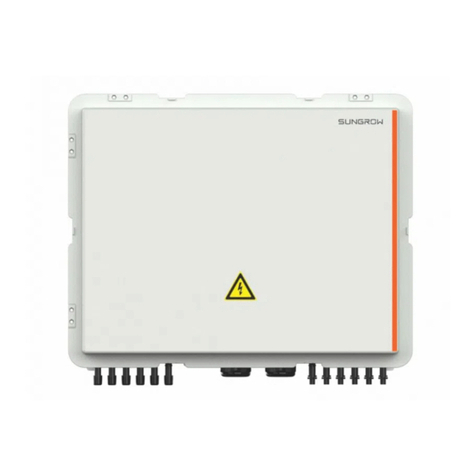
Sungrow PVS-8MH-DB User manual

PVS-12MH_16MH-DB-V11-UEN-Ver12-202006
User Manual
PVS-8MH-DB/ PVS-12MH-DB/PVS-16MH-DB
PV Array Combiner Box


Contents
1About This Manual..............................................................1
1.1 Contents....................................................................................1
1.2 Target Readers..........................................................................1
1.3 How to Use this Manual ............................................................1
1.4 Others .......................................................................................2
1.5 Symbol Explanation...................................................................2
1.6 Picture Explanation ...................................................................3
2Safety Instructions..............................................................4
3Product Description............................................................7
3.1 System introduction...................................................................7
3.2 Main features.............................................................................8
3.3 Demonstration of the type.........................................................8
3.4 Dimensions ...............................................................................8
3.5Identifying the PVS....................................................................9
4Mechanical Installation.....................................................10
4.1 Scope of Delivery....................................................................10
4.2 Installation site requirements...................................................10
4.3 Installation Tools...................................................................... 11
4.4 Installing PVS.......................................................................... 11
4.4.1 Overview ................................................................................. 11
4.4.2 Fix the Hangers to PVS...........................................................12
4.4.3 Fixing PVS to Installation Surface ...........................................12
5Electrical Installation ........................................................15
5.1 Internal structure .....................................................................15
5.2 Water-proof terminals..............................................................16
5.3 Wiring preparations .................................................................17
5.4 Connections ............................................................................18
5.4.1 Input connections.................................................................... 18
5.4.2 Output connections ................................................................. 22
5.4.3 Grounding connections ...........................................................23
5.4.4 Communication Connections...................................................24

5.4.5 Cable Layout........................................................................... 27
5.5 Communication settings...........................................................27
5.6 Start/Stop of operation .............................................................29
6Commissioning .................................................................30
7Routine Maintenance........................................................31
7.1 Replace the Fuse.....................................................................31
7.2 Replace the sealing strip..........................................................32
8Troubleshooting................................................................33
8.1 Before troubleshooting.............................................................33
8.2 Common faults and troubleshooting ........................................33
9Appendix............................................................................36
9.1 Technical data..........................................................................36
9.2 Quality Assurance....................................................................37
9.3 Contact Information..................................................................38

1
1 About This Manual
1.1 Contents
Safety instructions
Safety instructions for the installation, operation, commissioning and
maintenance of PVS.
Product description
Location of PVS in the PV system, structure, function and classification.
Installation guide
The installation methods and electrical connections of PVS.
Routine maintenance
How to replace the fuses of PVS.
Others
Technical data of PVS, exclusion of liability and the way to contact us.
1.2 Target Readers
This manual is for users who operate the PVS or conduct the maintenance work.
The operators must be trained and qualified personnel.
1.3 How to Use this Manual
Read this manual and other related documents before installation of the PVS.
Documents must be stored in a convenient place for future reference.
The contents of the manual will be periodically updated or revised due to the
product development. It is probably that there are changes of manual in the
subsequent converter edition.

1 About This Manual User Manual
2
1.4 Others
This document will take the PVS-16MH-DB for example. For the installation and
use of other types of combiner boxes, please also refer to this manual.
PVS-8MH-DB
PVS-12MH-DB
PVS-16MH-DB
The electrical structure, installation and use method of PVS-12MH-DB are the
same with that of PVS-16MH-DB. The only difference between them is the
numbers of DC input string.
1.5 Symbol Explanation
This manual contains important safety and operational instructions that must be
accurately understood and followed during the installation and maintenance of
the equipment.
To ensure optimum use of this manual, note the following explanations of
symbols used.
DANGER indicates a hazard with a high level of risk which, if not
avoided, will result in death or serious injury.
WARNING indicates a hazard with a medium level of risk which, if not
avoided, will result in death or serious injury.
CAUTION indicates a hazard with a low level of risk which, if not
avoided, will result in minor or moderate injury.
NOTICE indicates a situation which, if not avoided, will result in
equipment malfunction or property damage.

User Manual 1 About This Manual
3
NOTE indicates additional information, emphasized contents or tips
to help you solve problems or save time.
The following symbols on the device enclosure must be paid attention to.
Symbols
Explanation
Risk of electric shock! If not avoided, lethal hazard can be caused.
Hot surface! Do not touch!
The symbol represents protective conductor terminal. The terminal
should be connected firmly to avoid potential injury or property
damage.
1.6 Picture Explanation
Pictures used in this manual all take the PVS with standard configuration for
example.
The real PVS you received may differ from the example pictures in the numbers
of the installation hangers and etc. please refer to the actual product you
receive.

4
2 Safety Instructions
This chapter describes some important safety instructions about PVS.
Please read the manual carefully before installation. If any device damage
occurs when ignoring the safety instructions, our company has the right to
exclude all warranty claims.
Lethal Voltage!
Death resulting from burning and electric shock upon touching the
live components of the PVS.
Disconnect the end connection of the PV string before cable
connection;
Do not use ordinary ammeter to measure the DC voltage before
cable connection. An ammeter with withstanding voltage of 1500V is
recommended. Serious consequences may follow if otherwise.
Observe all safety instructions required by the PV cell manufacturer.
Device damage or system fault may cause fire and electric shock!
Optical check the device for any possible damages or dangerous
states before operation.
Check if other external devices or circuit connection are in safe state.
Work on the device only when it is safe to do so.
Death or burning hazard by touching the internal terminals of the
device!
Do not touch the terminals or conductors in contact to the inverter or
PV string.
Observe all the instructions and safety regulations related to PVS
connection.

User Manual 2 Safety Instructions
5
High voltage is present inside the device!
Follow all the warning signs in the device.
Respect all the safety instructions in this manual and other
documents.
The ground cable must be grounded properly, otherwise,
lethal electric shock happens to the operator or installer once a fault
occurs.
device may be damaged after lightening stroke.
Incorrect cable connection may cause damages to the PV cells, the
PVS and inverter. Respect the following instructions during cable
connection:
Connect by strictly following the circuit diagram;
Measure and make sure the string open-circuit voltage meets the
requirements of the PVS before inserting the fuse;
Identify the positive pole and negative pole before connection.
Only qualified personnel or professional electrician can perform the
operation and wiring described in this manual.
All operations and wirings must in full accordance with the national
and local standards and requirements.
All warning marks and labels must be clear and intact. Replace them
if any damages are found.

2 Safety Instructions User Manual
6
Make sure the terminals are firmly connected during wiring. If the cable
copper core and the terminals are not connected firmly, terminals will
be over-heating and burnt. Anti-flaming cables with multi-strand are
advisable and the cable cross-sectional area should be no less than
the recommended value.
The nuts of the water-proof terminals must be firmly screwed to
prevent water leakage and PVS damages.
Pull the fuse out of the fuse holder for personal and device safety.
Lock the cabinet door and seal the water-proof cover of the lock core
after operation.
No not open the cabinet door frequently.
Touching or improper operation on the PCB or other sensitive
components may damage the device.
Do not touch any parts inside the cabinet other than the connection
terminals.
Respect all ESD related safety regulations and wear antistatic wrist
strap.

7
3 Product Description
3.1 System introduction
For a large-scale grid-connected PV system, it is widespread to install a DC
combining device between PV modules and inverters to minimize cable
connections, facilitate maintenance and enhance reliability.
PVS is designed for meeting these requirements, which provides a turnkey
solution for PV plant systems.
Considering different types of PVS, a certain number of PV strings can be
connected to the input side of PVS. After combining work done, at the output
side, there will be one DC+ and one DC- main line. By using of surge protection
device (SPD) and DC switch, the output can be connected to inverters directly.
The PV generation system including a PVS is shown in following figure.
Fig. 3-1 Composition of PV generation system
Tab. 3-1 Device in above figure
No.
Device
A
PV arrays
B
PV Array combiner box
C
Inverter
D
Data acquisition device
E
Environment monitoring device
F
Grid

3 Product Description User Manual
8
3.2 Main features
Meet outdoor installation requirement
Connect to multiple PV inputs with fuse for each input (can be replaced to
other degree)
PV-specific high voltage SPD equipped, lightening protection function for
positive and negative pole
Current sensor inside to monitor the current of each string; the monitored
information can be displayed by the LED or sent by RS485
Monitor busbar voltage and the monitored information can be displayed by
the LED and sent by RS485
3.3 Demonstration of the type
Model
Max. Number of
DC inputs
Max.Number
of PV strings
Monitoring
function
PVS-8MH-DB
8
16
YES
PVS-12MH-DB
12
24
YES
PVS-16MH-DB
16
32
YES
3.4 Dimensions
The dimensions of the PVS are shown in the figure below, unit: mm.
Width(W)
Depth(D)
Height(H)

User Manual 3 Product Description
9
Model
Width(W)
Height(H)
Depth(D)
PVS-8MH-DB
730 mm
580 mm
260 mm
PVS-12MH-DB
PVS-16MH-DB
930 mm
730 mm
260 mm
3.5 Identifying the PVS
The appearance of the PVS is shown in the figure below (take PVS-16MH-DB
for example).
A
No.
Name
Description
A
Lockhole
A total of 6, two on the side surface, two on the top
and the bottom respectively.
Note: The figure above is based on PMS-16MH-DB, and the appearance of
other device type may slightly differ.

10
4 Mechanical Installation
4.1 Scope of Delivery
A B C
ED F
No
Name
Note
Quantity
A
PVS
-
1
B
Related documents
Including FQC test report,
Quality Certificate, Warranty
card, Manual, etc.
1
C
Keys
To open the cabinet of PVS.
2* / 2** / 4***
D
Bolt kit
M8 x 16
4
E
Hanger
Need to be installed to the PVS
cabinet onsite.
4
F
MC4 connector
Used to connect the PV input
8*/ 12** /
16***
Note: * is for the PVS-8MH-DB;** is for the PVS-12MH-DB; and *** is for the
PVS-16MH-DB.
4.2 Installation site requirements
With IP65 protection degree, the PVS can be installed outdoors. Please meet
the following requirements:
Dimensions and weight of PVS should be considered sufficiently.

User Manual 4 Mechanical Installation
11
Ambient temperature-30℃~+60℃; Relative humidity 0~95%
Installation site should be as close as possible to PV arrays for minimum
cables and wires usage.
Installation site should be safe venting.
Never install the device in direct sunlight to guarantee optimal performance.
For big PV plants, it is suggested that the device is installed on the back side
of PV arrays.
For better heat dissipation and convenient maintenance, enough space must
be maintained around the PVS.
For large-scale PV plant, install the PVS on the back of the PV cell
installation bracket.
Humidity during installation may damage the PVS. Do not install the
PVS during rainy or humidity days.
Screw the water-proof terminals tightly to prevent moisture penetration
no matter the installation is vertically or horizontally. Seal the unused
terminals after cable connection.
4.3 Installation Tools
Electric drill
Hex wrench
Bolt (M8 x 16)
M8 Allen wrench for tightening of output terminal
Screwdriver with withstanding voltage of 1500Vdc:
−Recommended model: 65-416-1
−Specification: 2#x125
4.4 Installing PVS
4.4.1 Overview
The PVS is fixed to the installation surface via the hangers in the scope of
delivery. Therefore, first fix the hangers to the PVS on site.

5 Electrical Installation User Manual
12
Mounting the PVS onto the installation surface is as described in the following
table.
Step
Description
Refer to
1
Fix the hangers to PVS.
4.2.2 Fix the hangers to PVS.
2
Fixing PVS to installation
surface.
4.4.3 Fixing PVS to Installation
Surface
4.4.2 Fix the Hangers to PVS
Install the hangers to the installation holes on the back of PVS with delivered
M8 x 16 bolts. The hangers can be installed horizontally or vertically.
For the vertical installation, the distances between hangers are shown in the
following figure "Solution 1".
For the horizontal installation, the distances between hangers are shown in the
following figure "Solution 2".
W1
H1
W2
H2
Solution 1 Solution 2
Hanger
Model
Solution 1
Solution 2
W1
H1
W2
H2
PVS-8MH-DB
621 mm
551 mm
702 mm
470 mm
PVS-12MH-DB
PVS-16MH-DB
816 mm
701 mm
897 mm
620 mm
On site, select an appropriate hanger installation solution according to the
installation plane, such as space condition of the bracket.
For ease of description, Solution 1 is used as an example hereinafter to give a
brief description of PVS mounting steps.
4.4.3 Fixing PVS to Installation Surface
The PVS can be installed in two manners: direct wall-mounted manner and
stainless steel wall-mounted manner.
On site, install the device in appropriate manner selected according to actual
conditions.

User Manual 4 Mechanical Installation
13
Direct wall-mounted
Step 1Mark position and drill holes on the installation surface according to the
distance of the hangers on the four corners of the PVS.
Step 2Fix the PVS to the surface according to the following sequence.
Recommended torque:51±0.7 N.m.
A B C D FE
No
Name
Note
A
M10 Bolt
Not included in the scope of delivery.
B
Flat washer
-
C
Spring washer
-
D
PVS hangers
-
E
Stainless steel support
-
F
Nut
-
Stainless steel wall-mounted
Step1 Mark position and drill holes on the frame according to the distance of
the hangers on the four corners of the PVS.
Step2 Fix the PVS to the surface according to the following sequence.
Recommended torque:51±0.7 N.m.

15
5 Electrical Installation
5.1 Internal structure
Two schemes are available for the combiner box: floating grounding and
negative grounding. Correspondingly, the internal structural diagram differs.
CD
I
J
K
L
AB
EF
G
H
Fig. 5-1 Floating grounding
CD
I
J
K
L
A
EF
G
H
Fig. 5-2 Negative grounding
No.
Description
A
DC+ fuse cartridge
B
DC- fuse cartridge
C
RS485 ports

5 Electrical Installation User Manual
16
No.
Description
D
Ground copper bar
E
Output of DC negative pole
F
Output of DC positive pole
G
DC switch
H
Power supply board
I
Indicator(for more details, please refer to the Tab 8-1)
J
LED display
K
Push switch
L
SPD (Surge protection device)
Fuse
A PV special fuse is set for each string as the upstream protection device of the
whole PV power generation system. Measure the voltage between the positive
and negative polarity of each input before inserting the PVS fuse to make sure
the voltage is within the range of 0 –1500Vdc. Make sure no PV module string
is connected reversely.
The monitoring board
The monitoring board monitors the current of each string. The monitored
current value is sent to the PC through RS485. The PC can judge if a fault is
occurred to the module through the set value.
SPD(Surge Protection Device)
A SPD is quipped inside the PVS to prevent the transient overvoltage caused
by lightning. The SPD failure signal can be sent to the PC through the RS485.
Grounding
It must be grounded properly for overvoltage protection. The PVS provides a
ground terminal for grounding connection.
5.2 Water-proof terminals
Water-proof terminals of PVS are shown as followings.
This manual suits for next models
2
Table of contents
Other Sungrow Controllers manuals