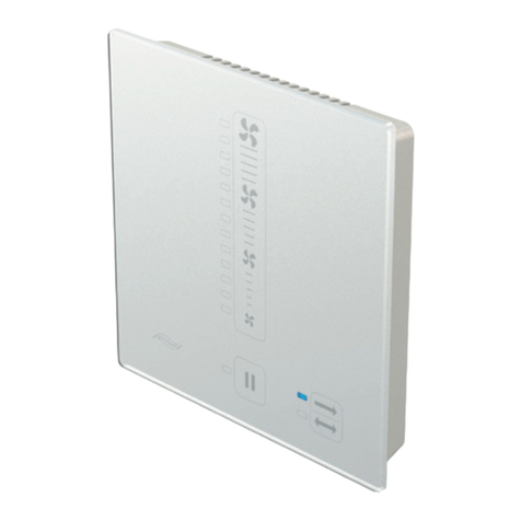
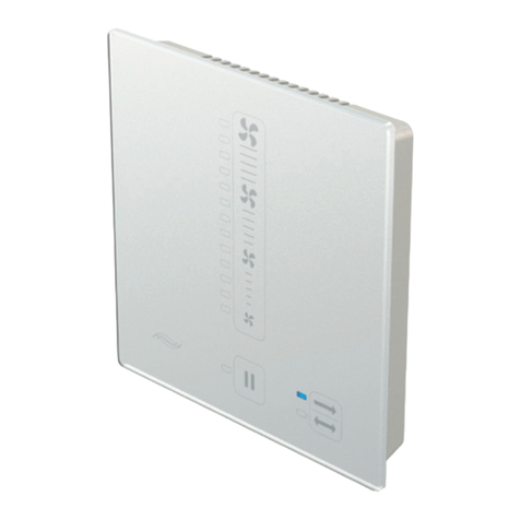
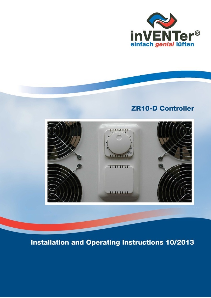
inVENTer ZR10-D User manual

ZR10-D
controller
Installation and operating instructions

2ZR10-D controller Installation and operating instructions
Trademarks
inVENTer®and iV12-Smart®are proprietary trademarks of inVENTer GmbH. Any other designation
used in this documentation may be a trademark whose use by any third party and for the purposes
of such third party may violate the rights of its holders.
Disclaimer of liability
This documentation is the English translation of the original German installation and operating
instructions. After completion of the installation, it should be passed onto the user (tenant, owner,
building management, etc.).
The contents of this documentation have been checked for compliance with the hardware and
software described. However, discrepancies cannot be ruled out, so complete compliance cannot be
guaranteed. This documentation will be updated on a regular basis. Any correction required or any
useful additions will be included in subsequent editions as a general rule.
Version 3.0.00

3
ZR10-D controller Installation and operating instructions
Table of contents
1 Safety........................................................................................................................................ 4
1.1 Safety instructions.......................................................................................................... 4
1.2 Understanding the safety instructions............................................................................ 4
1.3 Intended use .................................................................................................................. 5
1.4 Unauthorised use........................................................................................................... 5
1.5 ........................................................................................................ 5
2 System overview ..................................................................................................................... 6
2.1 Layout ............................................................................................................................ 7
2.2 Function ......................................................................................................................... 8
3 Controls.................................................................................................................................... 9
4 Electrical connections .......................................................................................................... 10
5 Preparations prior to installation ......................................................................................... 12
5.1 Dimensions .................................................................................................................. 12
5.2 Dimensioned drawings................................................................................................. 13
6 Assembly and installation .................................................................................................... 16
6.1 Making wall opening / boreholes.................................................................................. 16
6.2 Installing cables............................................................................................................ 18
6.3 .......................................................................... 21
6.4 Installing the surface mounted controller ..................................................................... 26
6.5 Installing the cabinet mounted controller ..................................................................... 31
6.6 Installing the ZR distributor (optional) ......................................................................... 37
7 Operation................................................................................................................................ 40
7.1 Setting the heat recovery mode ................................................................................... 40
7.2 Setting the ventilation mode......................................................................................... 40
7.3 Setting the sleep timer mode (ZR10-D-Flat controller only)......................................... 41
7.4 Setting the OFF mode (ZR10-D-Standard controller only)........................................... 41
8 .......................................................................................................................... 42
9 Standard delivery, accessories and spare parts ................................................................ 43
10 Servicing and maintenance .................................................................................................. 44
11 Troubleshooting and disposal ............................................................................................. 45
12 Warranty and service ............................................................................................................ 46
Company details.................................................................................................................... 47

4ZR10-D controller Installation and operating instructions
1 Safety
1.1 Safety instructions
The chapter on safety instructions contains basic instructions on how to operate the ZR10-D
controller safely.
All the instructions on installation, operation and maintenance of the ZR10-D controller listed in this
chapter must be observed. The safety instructions that precede the operating instructions must
also be observed.
1.2 Understanding the safety instructions
All operating instructions are preceded by safety instructions. Before working on the controller, read
the safety instructions carefully and make sure you understand them. Failure to observe safety
instructions can cause personal injury and material losses.
The safety instructions in these installation and operating instructions are set out in a standard way
level of danger involved.
DANGER
Type and source of the danger. Immediate risk of serious personal injury.
Possible consequences of the danger!
WARNING
Type and source of the danger. Possible risk of serious personal injury.
Possible consequences of the danger!
CAUTION
Type and source of the danger. Immediate or possible risk of slight/medium
personal injury or material loss.
Possible consequences of the danger!
BEWARE
Type and source of an undesirable event or state.
Possible consequences of the event or state!
SAFETY

5
ZR10-D controller Installation and operating instructions
Where several different hazard levels coincide, the warning notice for the highest level is always
used.
In addition to the safety instructions, an information symbol provides practical and useful tips for
using the controller
NOTE
Additional useful information.
1.3 Intended use
accident prevention regulations of the Employer's Liability Insurance Association.
Only use the controller in accordance with the applications described in this documentation and only
Trouble-free and safe operation of the controller can only be ensured provided it is transported,
stored and assembled correctly and operated and maintained with care. This documentation forms
part of the controller and must be available at all times. Observe all safety regulations in this
documentation.
This installation and operating instructions is only valid with the installation and operating instruc-
tions of the iV12-Smart, iV12-Smart Corner, iV12-Smart Ohio, iV14R, iV14R-Corner, iV14R-Ohio,
iV14R-Sylt, iV14V, iV14V-Ohio, iV14V-Corner, iV25, and iV-Twin ventilations systems and supple-
ments them. All legal notices given in the installation and operating instructions also apply to this
, Intended
1.4 Unauthorised use
-
mart Ohio, iV14R, iV14R-Corner, iV14R-Ohio, iV14R-Sylt, iV14V, iV14V-Ohio, iV14V-Corner, iV25,
and iV-Twin ventilation units. Any other use is strictly prohibited.
1.5
The controller may only be installed and operated in combination with this documentation. Instal-
personnel.
authorised to install, start up and identify equipment, systems and electrical circuits in accordance
with safety engineering standards.
SAFETY

SYSTEM OVERVIEW
6ZR10-D controller Installation and operating instructions
2 System overview
The ZR10-D controller is an electronic control unit for controlling of up to
4 ventilation units of iV12-Smart
4 ventilation units of iV14
2 ventilation units of iV25
2 ventilation units of iV-Twin
It is characterised by easy installation and straightforward operation. The ZR10-D controller allows
control of iV12-Smart, iV14, iV25 or iV-Twin ventilation units in the following operating modes:
Heat recovery mode
Ventilation mode
Sleep timer mode (ZR10-D-Flat controller only) or
OFF mode (ZR10-D-Standard controller only)
Characteristics
Control of the ventilation system in three operating modes
LED display depending on the operating mode selected
Synchronisation of multiple controllers among each other
Integrated thermostatic switch
Variants
The ZR10-D controller is available in two models1).
ZR10-D-Standard
ZR10-D-Flat
ZR10-D-Standard and ZR10-D-Flat
recommended in spaces with the requirement that the ventilation must remain ON to maintain venti-
lation for moisture protection. The power stages of the fan can be adjusted in all operating modes.
Power stage
ZR10-D-Standard ZR10-D-Flat
0 OFF 17
1 25
2 35
3 50
4 100
)115
)
1) Third party design also available on request.

SYSTEM OVERVIEW
7
ZR10-D controller Installation and operating instructions
2.1 Layout
5
1
2
3
4
Fig. 1: Front view of the ZR10-D controller
1 Frame 4 Ventilation slots
2 Cover operation unit 5 Blanking cover
3 Rotary button
1
2
5
3
4
7
6
Fig. 2: Front view of the ZR distributor
1 Cover of ZR distributor 5 Controller cable
2 6 Fan cable 3
3 Fan cable 1 7 Fan cable 4
4 Fan cable 2
The ZR distributor is available as an optional unit to realise a radially connection between the venti-
lation units and the ZR10-D controller.

SYSTEM OVERVIEW
8ZR10-D controller Installation and operating instructions
2.2 Function
Heat recovery mode
discharge mode at intervals of 70 seconds.
-
ent air. If the fan switches direction, it releases the stored thermal energy to the fresh air supplied.
This operating mode is the standard application during the heating season. In the summer, it is also
Ventilation mode
The fan operates with no directional change. The ventilation unit must be set to supply mode.
This operating mode is recommended for cooling spaces over summer nights.
Sleep timer mode
utes in the heat recovery mode with directional change and 17 % performance.
OFF mode
The OFF mode is only selectable at the ZR10-D-Standard controller. The fan of the ventilation unit is
switched off at power stage 0.
Synchronisation of multiple controllers
The ZR10-D controller allows synchronisation of multiple controllers among each other. It rates the
line frequency via the upstream transformer automatically and generates the interval switching of the
fans. The following requirements must be met.
Each controller is connected to the power supply via its own transformer.
The transformers of all controllers operating synchronously are connected on the same power
phase (all on P1, P2 or P3) . We recommend to connect all controller power supply lines to a
common automatic circuit breaker in the cabinet.
All controllers operating synchronously must be turned on simultaneously.
A fault-free power signal is available.

SYSTEM OVERVIEW
9
ZR10-D controller Installation and operating instructions
3 Controls
Display and operating elements
3
2
5
1
4
Fig. 3: Operating and display elements
1 Zero position 4 Marker point, power stages (1 ... 4)
2)5)
3
)LED is OFF when power stage is 0
Pin socket
1
2
Fig. 4: Back of the controller board
1 Controller board
2)
)For service settings only

ELECTRICAL CONNECTIONS
10 ZR10-D controller Installation and operating instructions
4 Electrical connections
DANGER
Exposed electrical components.
'Live' parts can cause electric shock and injury!
power supply.
BEWARE
Inadequate cable cross-section.
Only use these cable cross-sections for the electrical connection:
Fan bus: Minimum 0.75 mm2
Supply lines: Minimum 1.5 mm2
NOTE
ventilation unit:
2 iV12-Smart / iV14 ventilation units: 20 m (one after another)
Connector assignment
123
Round cable
Fig. 5: Colour sequences
1 White round cable 2 Green round cable 3 Brown round cable

ELECTRICAL CONNECTIONS
11
ZR10-D controller Installation and operating instructions
3
3
3
3
3
VI I
VIIII
III
VIV
III
III V
IV
III IV V VIV III III III
VV IV
IV
4
5
6
3
1
9
7
4
5
2
8
Fig. 6:
1 Lustre terminal Fan bus
Transformer input, 2-pole, 230 V, 50 Hz III White (–) Supply air
2 Transformer, 30 VA IV Green (+) Operating voltage
3 Controller board, rear side V Brown (–)
4 Fans 1 ... 4 Power supply lines
5 Plug connector of the fan bus VI Brown (phase) Mains voltage
6 ZR distributor (optional) VII Blue (neutral)
7 Cabinet of the indoor installation I Red Operating voltage
(controller)
8 Residual current protective device (RCD) II Black
9 Circuit breakers
Interfaces
1
2
Fig. 7: Back of the controller board with interfaces
1 2-pin transformer socket
2 3-pin fan socket

12 ZR10-D controller Installation and operating instructions
5 Preparations prior to installation
5.1 Dimensions
DANGER
Confusion between circuits.
Short circuit causes overheating and electric shock!
power supply.
NOTE
Description
68 140 75 68
68 142 74 68
80 152 41 -
71 143 56 -
)- - 87 74
)- - 87 75
)When using a distributor only
PREPARATIONS PRIOR TO INSTALLATION

13
ZR10-D controller Installation and operating instructions
5.2 Dimensioned drawings
Flush mounted dual box
60 74
142
71
Ø 68
2
1
3
Fig. 8:
1
2
3screw for support ring
Surface mounted box
41
152
80
2
40
Ø
12
72
4
38
1
2
3
5
6
Fig. 9:
1 Cable entry for fan cable 4 Separating plate
2 Borehole for 5
3 F for controller board 6 Cable entry for power cable
PREPARATIONS PRIOR TO INSTALLATION

14 ZR10-D controller Installation and operating instructions
Cabinet box
71
143
56
2
1
3
2
Fig. 10:
1
2 Separating plate
3 F for support ring
72
144
304 94
245
4 x R5
3
2
1
Fig. 11:
1 Cabinet cover
2 Front panel
3 Cut-out
PREPARATIONS PRIOR TO INSTALLATION

15
ZR10-D controller Installation and operating instructions
Cutting template
72
144
46
134
62
4 x R5
1
2
3
Fig. 12: Dimensioned drawing for the cutting template
1 Corner drilling
2 Top-hat rail
3 Cutting template
61
71
Ø
75 87
Ø
70
1
Fig. 13:
1
PREPARATIONS PRIOR TO INSTALLATION

16 ZR10-D controller Installation and operating instructions
6 Assembly and installation
6.1 Making wall opening / boreholes
DANGER
Flush mounted cables.
Short circuit causes electric shock!
CAUTION
Falling masonry while making a wall opening.
Requirements:
Masonry must be dry and load-bearing.
Avoid lintels when drilling wall opening.
Fit two wall openings (Ø 68 mm) f
.
Ensure the distance of the centres of the
wall openings is 71 mm. Ø 68
71
Remove ridges (dashed line) between the
wall openings.
ASSEMBLY AND INSTALLATION

17
ZR10-D controller Installation and operating instructions
Making boreholes for surface mounted box
BEWARE
Surface mounted box installed in false position.
Transformer of the ZR10-D controller can not be installed!
Requirements:
Masonry must be dry and load-bearing.
Avoid lintels when drilling boreholes.
Drill boreholes (Ø 8 mm) for rawl plugs on
interior wall.
Drill boreholes (Ø 12 mm) for power cable /
fan cable on interior wall.
12
72
19
8
Ö
NOTE
controller and the ZR distributor.
Requirements:
Masonry must be dry and load-bearing.
Avoid lintels when drilling wall opening.
(Ø 74 mm) f
.
Ø 74
Wall opening for ZR distributor is ready.
ASSEMBLY AND INSTALLATION

18 ZR10-D controller Installation and operating instructions
6.2 Installing cables
DANGER
Exposed electrical components.
'Live' parts can cause electric shock and injury!
power supply.
CAUTION
.
Short circuit caused by penetrating moisture!
► Lay cables inside a conduit.
NOTE
When using a ZR distributor (optional) lay fan cable to the distributor.
Requirements:
Wall opening is ready.
power cable (2) to the wall opening (1).
150 mm out of the wall opening (1). 1
2
Power cable is installed.
ASSEMBLY AND INSTALLATION

19
ZR10-D controller Installation and operating instructions
Requirements:
Wall opening is ready.
Power cable is installed.
round cable (1) from fan to the
150 mm out of the wall opening (2).
1
2
Fan cable is installed.
Requirements:
Boreholes are ready.
Install power cable (2) to the lower borehole (1).
150 mm out of the borehole (1).
1
2
Power cable is installed.
ASSEMBLY AND INSTALLATION

20 ZR10-D controller Installation and operating instructions
Requirements:
Boreholes are ready.
Power cable in place.
Install 3-wire round fan cable (2) from fan to the
upper borehole (1).
1
2
Ö Fan cable is installed.
ASSEMBLY AND INSTALLATION
Other manuals for ZR10-D
1
Table of contents
Other inVENTer Controllers manuals

inVENTer
inVENTer MZ-One User manual

inVENTer
inVENTer sMove S4 Long User manual

inVENTer
inVENTer sMove S4 Long User manual

inVENTer
inVENTer Easy Connect e16 User manual

inVENTer
inVENTer Easy Connect e16 User manual

inVENTer
inVENTer Easy Connect e16 User manual

inVENTer
inVENTer sMove S8 Long User manual

inVENTer
inVENTer iV14-Zero sMove User manual

inVENTer
inVENTer sMove User guide

inVENTer
inVENTer Connect. User manual