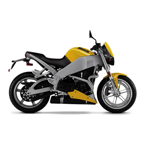
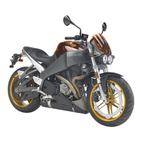
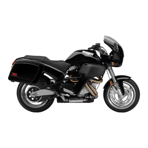
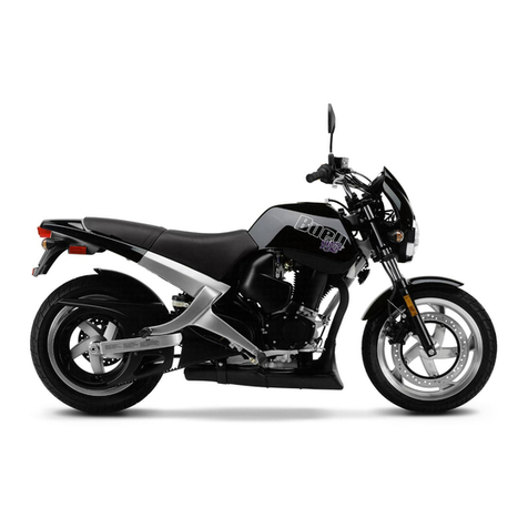
Buell S1 Lightning 1996 User manual

www.PlanDeGraissage.org

MAINTENANCE
General . . . . . . . . . . . . . . . . . . . . . . . . . . . . . . . . . . . . . . . 1-1
1996 S1-Lightning Specifications . . . . . . . . . . . . . . . . . . . 1-5
Side Views . . . . . . . . . . . . . . . . . . . . . . . . . . . . . . . . . . . . 1-6
Fluid Requirements. . . . . . . . . . . . . . . . . . . . . . . . . . . . . . 1-8
Regular Maintenance Intervals (table) . . . . . . . . . . . . . . . 1-9
Battery. . . . . . . . . . . . . . . . . . . . . . . . . . . . . . . . . . . . . . . . 1-13
Engine Lubrication System. . . . . . . . . . . . . . . . . . . . . . . . 1-15
Brakes. . . . . . . . . . . . . . . . . . . . . . . . . . . . . . . . . . . . . . . . 1-17
Tires and Wheels . . . . . . . . . . . . . . . . . . . . . . . . . . . . . . . 1-18
Clutch . . . . . . . . . . . . . . . . . . . . . . . . . . . . . . . . . . . . . . . . 1-19
Rear Belt Deflection . . . . . . . . . . . . . . . . . . . . . . . . . . . . . 1-21
Primary Chain . . . . . . . . . . . . . . . . . . . . . . . . . . . . . . . . . . 1-22
Rear Preload Adjustment. . . . . . . . . . . . . . . . . . . . . . . . . 1-23
Suspension. . . . . . . . . . . . . . . . . . . . . . . . . . . . . . . . . . . . 1-24
Front Fork . . . . . . . . . . . . . . . . . . . . . . . . . . . . . . . . . . . . 1-25
Spark Plugs . . . . . . . . . . . . . . . . . . . . . . . . . . . . . . . . . . . 1-27
Air Cleaner Filter. . . . . . . . . . . . . . . . . . . . . . . . . . . . . . . . 1-28
Carburetor . . . . . . . . . . . . . . . . . . . . . . . . . . . . . . . . . . . . 1-29
Ignition Timing . . . . . . . . . . . . . . . . . . . . . . . . . . . . . . . . . 1-30
Vacuum-Operated Electrical Switch (V.O.E.S.). . . . . . . . 1-32
Handlebars. . . . . . . . . . . . . . . . . . . . . . . . . . . . . . . . . . . . 1-33
Headlamp. . . . . . . . . . . . . . . . . . . . . . . . . . . . . . . . . . . . . 1-34
Storage. . . . . . . . . . . . . . . . . . . . . . . . . . . . . . . . . . . . . . . 1-35
Troubleshooting . . . . . . . . . . . . . . . . . . . . . . . . . . . . . . . . 1-36
www.PlanDeGraissage.org

CHASSIS
Specifications . . . . . . . . . . . . . . . . . . . . . . . . . . . . . . . . . . 2-1
Tire Specifications . . . . . . . . . . . . . . . . . . . . . . . . . . . . . . 2-4
Vehicle Identification Number . . . . . . . . . . . . . . . . . . . . . 2-5
Wheels . . . . . . . . . . . . . . . . . . . . . . . . . . . . . . . . . . . . . . . 2-6
Front Wheel . . . . . . . . . . . . . . . . . . . . . . . . . . . . . . . . . . . 2-8
Rear Wheel . . . . . . . . . . . . . . . . . . . . . . . . . . . . . . . . . . . 2-11
Checking Cast Rim Runout . . . . . . . . . . . . . . . . . . . . . . . 2-14
Tires . . . . . . . . . . . . . . . . . . . . . . . . . . . . . . . . . . . . . . . . . 2-15
Brakes . . . . . . . . . . . . . . . . . . . . . . . . . . . . . . . . . . . . . . . 2-18
Front Brake Master Cylinder . . . . . . . . . . . . . . . . . . . . . . 2-19
Front Brake Caliper . . . . . . . . . . . . . . . . . . . . . . . . . . . . . 2-20
Front Brake Line . . . . . . . . . . . . . . . . . . . . . . . . . . . . . . . . 2-22
Rear Brake Master Cylinder . . . . . . . . . . . . . . . . . . . . . . . 2-23
Rear Brake Caliper . . . . . . . . . . . . . . . . . . . . . . . . . . . . . . 2-25
Rear Brake Line and Switch . . . . . . . . . . . . . . . . . . . . . . 2-27
Front Fork . . . . . . . . . . . . . . . . . . . . . . . . . . . . . . . . . . . . . 2-28
Fork Stem and Bracket Assembly . . . . . . . . . . . . . . . . . . 2-32
Swingarm . . . . . . . . . . . . . . . . . . . . . . . . . . . . . . . . . . . . . 2-33
Rear Shock Absorber . . . . . . . . . . . . . . . . . . . . . . . . . . . 2-36
Suspension Theory . . . . . . . . . . . . . . . . . . . . . . . . . . . . . 2-38
Suspension Adjustments . . . . . . . . . . . . . . . . . . . . . . . . . 2-39
Throttle Control . . . . . . . . . . . . . . . . . . . . . . . . . . . . . . . . 2-43
Clutch Control . . . . . . . . . . . . . . . . . . . . . . . . . . . . . . . . . 2-44
Speedometer and Tachometer . . . . . . . . . . . . . . . . . . . . 2-46
Handlebars . . . . . . . . . . . . . . . . . . . . . . . . . . . . . . . . . . . 2-49
Exhaust System . . . . . . . . . . . . . . . . . . . . . . . . . . . . . . . 2-50
Footrests . . . . . . . . . . . . . . . . . . . . . . . . . . . . . . . . . . . . . 2-52
Sprocket Cover . . . . . . . . . . . . . . . . . . . . . . . . . . . . . . . . 2-53
Fenders . . . . . . . . . . . . . . . . . . . . . . . . . . . . . . . . . . . . . . 2-54
Tail Section . . . . . . . . . . . . . . . . . . . . . . . . . . . . . . . . . . . 2-55
Windscreen . . . . . . . . . . . . . . . . . . . . . . . . . . . . . . . . . . . 2-56
Seat . . . . . . . . . . . . . . . . . . . . . . . . . . . . . . . . . . . . . . . . . 2-57
Side Stand . . . . . . . . . . . . . . . . . . . . . . . . . . . . . . . . . . . . 2-58
www.PlanDeGraissage.org

ENGINE
Specifications . . . . . . . . . . . . . . . . . . . . . . . . . . . . . . . . . . 3-1
Engine . . . . . . . . . . . . . . . . . . . . . . . . . . . . . . . . . . . . . . . 3-5
Stripping Motorcycle For Engine Repair . . . . . . . . . . . . . 3-8
Installing The Engine . . . . . . . . . . . . . . . . . . . . . . . . . . . . 3-10
Cylinder Head . . . . . . . . . . . . . . . . . . . . . . . . . . . . . . . . . 3-11
Cylinder and Piston . . . . . . . . . . . . . . . . . . . . . . . . . . . . . 3-22
Lubrication System . . . . . . . . . . . . . . . . . . . . . . . . . . . . . . 3-28
Oil Hose Routing . . . . . . . . . . . . . . . . . . . . . . . . . . . . . . . 3-29
Oil Tank . . . . . . . . . . . . . . . . . . . . . . . . . . . . . . . . . . . . . . 3-30
Oil Pressure Signal Light Switch . . . . . . . . . . . . . . . . . . . 3-31
Crankcase Breathing System . . . . . . . . . . . . . . . . . . . . . 3-32
Oiling System (Color Foldout) . . . . . . . . . . . . . . . . . . . . . 3-33
Oil Pump . . . . . . . . . . . . . . . . . . . . . . . . . . . . . . . . . . . . . 3-34
Oil Filter Mount . . . . . . . . . . . . . . . . . . . . . . . . . . . . . . . . 3-37
Valve Tappets . . . . . . . . . . . . . . . . . . . . . . . . . . . . . . . . . 3-38
Gearcase Cover and Cam Gears . . . . . . . . . . . . . . . . . . 3-40
Crankcase . . . . . . . . . . . . . . . . . . . . . . . . . . . . . . . . . . . . 3-48
www.PlanDeGraissage.org

FUEL SYSTEM
Specifications . . . . . . . . . . . . . . . . . . . . . . . . . . . . . . . . . . 4-1
Carburetor . . . . . . . . . . . . . . . . . . . . . . . . . . . . . . . . . . . . 4-2
Air Cleaner . . . . . . . . . . . . . . . . . . . . . . . . . . . . . . . . . . . . 4-18
Fuel Tank . . . . . . . . . . . . . . . . . . . . . . . . . . . . . . . . . . . . . 4-20
Fuel Supply Valve . . . . . . . . . . . . . . . . . . . . . . . . . . . . . . 4-22
Evaporative Emissions Control-California Models . . . . . 4-23
www.PlanDeGraissage.org

ELECTRIC STARTER
Specifications . . . . . . . . . . . . . . . . . . . . . . . . . . . . . . . . . . 5-1
Electric Starter System . . . . . . . . . . . . . . . . . . . . . . . . . . . 5-2
Diagnostics/Troubleshooting . . . . . . . . . . . . . . . . . . . . . . 5-9
Starter System Testing . . . . . . . . . . . . . . . . . . . . . . . . . . 5-10
Starter . . . . . . . . . . . . . . . . . . . . . . . . . . . . . . . . . . . . . . . 5-11
Starter Solenoid . . . . . . . . . . . . . . . . . . . . . . . . . . . . . . . . 5-18
www.PlanDeGraissage.org

DRIVE/TRANSMISSION
Specifications . . . . . . . . . . . . . . . . . . . . . . . . . . . . . . . . . . 6-1
Primary Chain . . . . . . . . . . . . . . . . . . . . . . . . . . . . . . . . . 6-3
Secondary Drive Belt . . . . . . . . . . . . . . . . . . . . . . . . . . . . 6-6
Clutch . . . . . . . . . . . . . . . . . . . . . . . . . . . . . . . . . . . . . . . . 6-8
Clutch Release Mechanism . . . . . . . . . . . . . . . . . . . . . . . 6-9
Primary Drive/Clutch . . . . . . . . . . . . . . . . . . . . . . . . . . . . 6-10
Transmission . . . . . . . . . . . . . . . . . . . . . . . . . . . . . . . . . . 6-14
Transmission Case . . . . . . . . . . . . . . . . . . . . . . . . . . . . . 6-16
Shifter Forks and Drum . . . . . . . . . . . . . . . . . . . . . . . . . . 6-18
Mainshaft and Countershaft . . . . . . . . . . . . . . . . . . . . . . 6-20
Main Drive Gear . . . . . . . . . . . . . . . . . . . . . . . . . . . . . . . 6-26
Access Door Bearings . . . . . . . . . . . . . . . . . . . . . . . . . . . 6-28
Right Transmission Case Bearings . . . . . . . . . . . . . . . . . 6-29
Transmission Installation and Shifter Pawl Adjustment . 6-30
www.PlanDeGraissage.org

ELECTRICAL
Specifications . . . . . . . . . . . . . . . . . . . . . . . . . . . . . . . . . . 7-1
Ignition System . . . . . . . . . . . . . . . . . . . . . . . . . . . . . . . . . 7-3
Vacuum-Operated Electrical Switch (V.O.E.S.) . . . . . . . . 7-10
Ignition/Headlamp Switch . . . . . . . . . . . . . . . . . . . . . . . . . 7-11
Ignition Module . . . . . . . . . . . . . . . . . . . . . . . . . . . . . . . . . 7-13
Ignition Sensor Plate and Rotor . . . . . . . . . . . . . . . . . . . . 7-14
Ignition Coil . . . . . . . . . . . . . . . . . . . . . . . . . . . . . . . . . . . . 7-16
Spark Plug Cables . . . . . . . . . . . . . . . . . . . . . . . . . . . . . . 7-18
Starter Interlock . . . . . . . . . . . . . . . . . . . . . . . . . . . . . . . . 7-19
Charging System . . . . . . . . . . . . . . . . . . . . . . . . . . . . . . . 7-23
Alternator . . . . . . . . . . . . . . . . . . . . . . . . . . . . . . . . . . . . . 7-29
Voltage Regulator . . . . . . . . . . . . . . . . . . . . . . . . . . . . . . 7-31
Battery . . . . . . . . . . . . . . . . . . . . . . . . . . . . . . . . . . . . . . . 7-32
Headlamp . . . . . . . . . . . . . . . . . . . . . . . . . . . . . . . . . . . . 7-33
Tail Lamp . . . . . . . . . . . . . . . . . . . . . . . . . . . . . . . . . . . . . 7-35
Turn Signals . . . . . . . . . . . . . . . . . . . . . . . . . . . . . . . . . . 7-37
Turn Signal Flasher . . . . . . . . . . . . . . . . . . . . . . . . . . . . . 7-38
Handlebar Switches . . . . . . . . . . . . . . . . . . . . . . . . . . . . 7-39
Horn . . . . . . . . . . . . . . . . . . . . . . . . . . . . . . . . . . . . . . . . . 7-41
Neutral Indicator Switch . . . . . . . . . . . . . . . . . . . . . . . . . 7-42
Fuses and Circuit Breakers . . . . . . . . . . . . . . . . . . . . . . . 7-43
Electrical Connectors . . . . . . . . . . . . . . . . . . . . . . . . . . . 7-44
DeutschElectrical Connectors . . . . . . . . . . . . . . . . . . . . 7-46
Amp Multilock Electrical Connectors . . . . . . . . . . . . . . . . 7-48
www.PlanDeGraissage.org

1997 INFORMATION
Maintenance . . . . . . . . . . . . . . . . . . . . . . . . . . . . . . . . . . . 1
Chassis . . . . . . . . . . . . . . . . . . . . . . . . . . . . . . . . . . . . . . . 11
Engine. . . . . . . . . . . . . . . . . . . . . . . . . . . . . . . . . . . . . . . . 17
Fuel System . . . . . . . . . . . . . . . . . . . . . . . . . . . . . . . . . . . 19
Electric Starter . . . . . . . . . . . . . . . . . . . . . . . . . . . . . . . . . 25
Drive/transmission . . . . . . . . . . . . . . . . . . . . . . . . . . . . . . 29
Electrical. . . . . . . . . . . . . . . . . . . . . . . . . . . . . . . . . . . . . . 31
www.PlanDeGraissage.org

APPENDIX
Tools . . . . . . . . . . . . . . . . . . . . . . . . . . . . . . . . . . . . . . . . . A-1 Metric Conversion . . . . . . . . . . . . . . . . . . . . . . . . . . . . . . B-1
www.PlanDeGraissage.org

1-1
SERVICING A NEW MOTORCYCLE
WARNING
Always follow the listed service and maintenance
recommendations, since they affect the safe operation of
the motorcycle and the personal welfare of the rider.
Failure to follow recommendations may cause personal
injury.
Service operations to be performed before customer delivery
are specified in the applicable model year PREDELIVERY
AND SETUP MANUAL.
The performance of new motorcycle initial service is required
to keep warranty in force and to ensure proper emissions
systems operation.
After a new motorcycle has been driven its first 500 miles,
and again at 2500 mile intervals, a Buell dealer should
perform the service operations listed in the REGULAR
MAINTENANCE INTERVALS chart on page 1-9.
SAFE OPERATING MAINTENANCE
A careful check of certain equipment is necessary after
periods of storage, and frequently between regular service
intervals, to determine if additional maintenance is required.
CAUTION
Do not attempt to retighten engine head bolts.
Retightening can cause engine damage.
During the initial 500 mile (800 km) break-in period,
use only 20W50 engine oil. Failure to use the
recommended oil will result in improper break-in of
the engine cylinders and piston rings.
Do not lubricate the enrichment cable on C.V.
carburetors. The cable requires friction to operate
properly.
Check:
1. Tires for abrasions, cuts and correct pressure.
2. Secondary drive belt for proper tension and condition.
3. Brakes, steering and throttle for responsiveness.
4. Brake fluid level and condition. Hydraulic lines and
fittings for leaks. Also, check brake pads and rotors for
wear.
5. Cables for fraying, crimping and free operation.
6. Engine oil and transmission fluid levels.
7. Headlamp, passing lamp, tail lamp, brake lamp and turn
signal operation.
SHOP PRACTICES
Repair Notes
All special tools and torque values are noted at the point of
use.
All required parts or materials can be found in the appropriate
PARTS CATALOG.
Safety
Safety is always the most important consideration when
performing any job. Be sure you have a complete
understanding of the task to be performed. Use common
sense. Use the proper tools. Protect yourself and bystanders
with approved eye protection. Don’t just do the job – do the
job safely.
Removing Parts
Always consider the weight of a part when lifting. Use a hoist
whenever necessary. Do not lift heavy parts by hand. A hoist
and adjustable lifting beam or sling are needed to remove
some parts. The lengths of chains or cables from the hoist to
the part should be equal and parallel and should be
positioned directly over the center of the part. Be sure that no
obstructions will interfere with the lifting operation. Never
leave a part suspended in mid-air.
Always use blocking or proper stands to support the part that
has been hoisted. If a part cannot be removed, verify that all
bolts and attaching hardware have been removed. Check to
see if any parts are in the way of the part being removed.
When removing hoses, wiring or tubes, always tag each part
to ensure proper installation.
Cleaning
If you intend to reuse parts, follow good shop practice and
thoroughly clean the parts before assembly. Keep all dirt out
of parts; the unit will perform better and last longer. Seals,
filters and covers are used in this vehicle to keep out
environmental dirt and dust. These items must be kept in
good condition to ensure satisfactory operation.
Clean and inspect all parts as they are removed. Be sure all
holes and passages are clean and open. After cleaning,
cover all parts with clean lint-free cloth, paper or other
material. Be sure the part is clean when it is installed.
Always clean around lines or covers before they are removed.
Plug, tape or cap holes and openings to keep out dirt, dust
and debris.
GENERAL
1
www.PlanDeGraissage.org

1-2
Disassembly and Assembly
Always assemble or disassemble one part at a time. Do not
work on two assemblies simultaneously. Be sure to make all
necessary adjustments. Recheck your work when finished.
Be sure that everything is done.
Operate the vehicle to perform any final check or
adjustments. If all is correct, the vehicle is ready to go back to
the customer.
REPAIR AND REPLACEMENT
PROCEDURES
Hardware andThreaded Parts
Install helical thread inserts when inside threads in castings
are stripped, damaged or not capable of withstanding
specified torque.
Replace bolts, nuts, studs, washers, spacers and small
common hardware if missing or in any way damaged. Clean
up or repair minor thread damage with a suitable tap or die.
Replace all damaged or missing lubrication fittings.
Use Teflon pipe sealant on pipe fitting threads.
Wiring, Hoses and Lines
Replace hoses, clamps, electrical wiring, electrical switches
or fuel lines if they do not meet specifications.
Instruments and Gauges
Replace broken or defective instruments and gauges.
Replace dials and glass that are so scratched or discolored
that reading is difficult.
Bearings
Anti-friction bearings must be handled in a special way. To
keep out dirt and abrasives, cover the bearings as soon as
they are removed from the package.
Wash bearings in a non-flammable cleaning solution. Knock
out packed lubricant inside by tapping the bearing against a
wooden block. Wash bearings again. Cover bearings with
clean material after setting them down to dry. Never use
compressed air to dry bearings.
Coat bearings with clean oil. Wrap bearings in clean paper.
Be sure that the chamfered side of the bearing always faces
the shoulder (when bearings installed against shoulders).
Lubricate bearings and all metal contact surfaces before
pressing into place. Only apply pressure on the part of the
bearing that makes direct contact with the mating part.
Always use the proper tools and fixtures for removing and
installing bearings.
Bearings do not usually need to be removed. Only remove
bearings if necessary.
Bushings
Do not remove a bushing unless damaged, excessively worn
or loose in its bore. Press out bushings that must be replaced.
When pressing or driving bushings, be sure to apply pressure
in line with the bushing bore. Use a bearing/bushing driver or
a bar with a smooth, flat end. Never use a hammer to drive
bushings.
Inspect the bushing and the mated part for oil holes. Be sure
all oil holes are properly aligned.
Gaskets
Always discard gaskets after removal. Replace with new
gaskets. Never use the same gasket twice. Be sure that
gasket holes match up with holes in the mating part.
LipType Seals
Lip seals are used to seal oil or grease and are usually
installed with the sealing lip facing the contained lubricant.
Seal orientation, however, may vary under different
applications.
Seals should not be removed unless necessary. Only remove
seals if required to gain access to other parts or if seal
damage or wear dictates replacement.
Leaking oil or grease usually means that a seal is damaged.
Replace leaking seals to prevent overheated bearings.
Always discard seals after removal. Do not use the same seal
twice.
O-Rings (Preformed Packings)
Always discard O-rings after removal. Replace with new O-
rings. To prevent leaks, lubricate the O-rings before
installation. Apply the same type of lubricant as that being
sealed. Be sure that all gasket, O-ring and seal mating
surfaces are thoroughly clean before installation.
Gears
Always check gears for damaged or worn teeth.
Lubricate mating surfaces before pressing gears on shafts.
Shafts
If a shaft does not come out easily, check that all nuts, bolts or
retaining rings have been removed. Check to see if other
parts are in the way before using force.
Shafts fitted to tapered splines should be very tight. If shafts
are not tight, disassemble and inspect tapered splines.
Discard parts that are worn. Be sure tapered splines are
clean, dry and free of burrs before putting them in place.
Press mating parts together tightly.
Clean all rust from the machined surfaces of new parts.
www.PlanDeGraissage.org

1-3
Part Replacement
Always replace worn or damaged parts with new parts.
CLEANING
Part Protection
Before cleaning, protect rubber parts (such as hoses, boots
and electrical insulation) from cleaning solutions. Use a
grease-proof barrier material. Remove the rubber part if it
cannot be properly protected.
Cleaning Process
Any cleaning method may be used as long as it does not
result in parts damage. Thorough cleaning is necessary for
proper parts inspection. Strip rusted paint areas to bare metal
before repainting.
Rust or Corrosion Removal
Remove rust and corrosion with a wire brush, abrasive cloth,
sand blasting, vapor blasting or rust remover. Use buffing
crocus cloth on highly polished parts that are rusted.
Bearings
Remove shields and seals from bearings before cleaning.
Clean bearings with permanent shields and seals in solution.
Clean open bearings by soaking them in a petroleum
cleaning solution. Never use a solution that contains chlorine.
Let bearings stand and dry. Do not dry using compressed air.
Do not spin bearings while they are drying.
TOOL SAFETY
AirTools
Always use approved eye protection equipment when
performing any task using air-operated tools.
On all power tools, use only recommended accessories
with proper capacity ratings.
Do not exceed air pressure ratings of any power tools.
Bits should be placed against work surface before air
hammers are operated.
Disconnect the air supply line to an air hammer before
attaching a bit.
Never point an air tool at yourself or another person.
Protect bystanders with approved eye protection.
Wrenches
Never use an extension on a wrench handle.
If possible, always pull on a wrench handle and adjust
your stance to prevent a fall if something lets go.
Never cock a wrench.
Never use a hammer on any wrench other than a
STRIKING FACE wrench.
Discard any wrench with broken or battered points.
Never use a pipe wrench to bend, raise or lift a pipe.
Pliers/cutters/prybars
Plastic- or vinyl-covered pliers handles are not intended
to act as insulation; don’t use on live electrical circuits.
Don’t use pliers or cutters for cutting hardened wire
unless they were designed for that purpose.
Always cut at right angles.
Don’t use any prybar as a chisel, punch or hammer.
Hammers
Never strike one hammer against a hardened object,
such as another hammer.
Always grasp a hammer handle firmly, close to the end.
Strike the object with the full face of the hammer.
Never work with a hammer which has a loose head.
Discard hammer if face is chipped or mushroomed.
Wear approved eye protection when using striking tools.
Protect bystanders with approved eye protection.
www.PlanDeGraissage.org

1-4
Punches/chisels
Never use a punch or chisel with a chipped or
mushroomed end; dress mushroomed chisels and
punches with a file.
Hold a chisel or a punch with a tool holder if possible.
When using a chisel on a small piece, clamp the piece
firmly in a vise and chip toward the stationary jaw.
Wear approved eye protection when using these tools.
Protect bystanders with approved eye protection.
Screwdrivers
Don’t use a screwdriver for prying, punching, chiseling,
scoring or scraping.
Use the right type of screwdriver for the job; match the tip
to the fastener.
Don’t interchange POZIDRIV®, PHILLIPS®or REED
AND PRINCE screwdrivers.
Screwdriver handles are not intended to act as
insulation; don’t use on live electrical circuits.
Don’t use a screwdriver with rounded edges because it
will slip – redress with a file.
Ratchets and Handles
Periodically clean and lubricate ratchet mechanisms with
a light grade oil. Do not replace parts individually;
ratchets should be rebuilt with the entire contents of
service kit.
Never hammer or put a pipe extension on a ratchet or
handle for added leverage.
Always support the ratchet head when using socket
extensions, but do not put your hand on the head or you
may interfere with the action of its reversing mechanism.
When breaking loose a fastener, apply a small amount of
pressure as a test to be sure the ratchet’s gear wheel is
engaged with the pawl.
Sockets
Never use hand sockets on power or impact wrenches.
Select the right size socket for the job.
Never cock any wrench or socket.
Select only impact sockets for use with air or electric
impact wrenches.
Replace sockets showing cracks or wear.
Keep sockets clean.
Always use approved eye protection when using power
or impact sockets.
Storage Units
Don’t open more than one loaded drawer at a time.Close
each drawer before opening up another.
Close lids and lock drawers and doors before moving
storage units.
Don’t pull on a tool cabinet; push it in front of you.
Set the brakes on the locking casters after the cabinet
has been rolled to your work.
www.PlanDeGraissage.org

1-5
1996 S1 LIGHTNING SPECIFICATIONS
I
*Final gear ratios indicate number of mainshaft revolutions
required to drive output sprocket one revolution.
**Overall gear ratios indicate number of engine revolutions
required to drive rear wheel one revolution.
WARNING
Do not inflate any tire beyond its maximum inflation
pressure as specified on tire sidewall. Overinflation may
cause tire to suddenly deflate leading to personal injury.
DIMENSIONS IN. MM
Wheel base 55 1397
Overall length 79.5 2019
Overall width 30 762
Road clearance 5.2 132
Seat height 29.5 749
CAPACITIES U.S. LITERS
Fuel tank (including reserve) 4.0 gallons 15.14
Reserve 0.6 gallons 2.27
Oil tank 2.0 quarts 1.89
Transmission 1.0 quart 0.95
WEIGHT LBS. KG
S1 shipping weight 446 202
GVWR 820 372
GAWR - Front 340 154
GAWR - Rear 480 218
ENGINE
Number of cylinders 2
Type 4-Cycle, 45 Degree V-Type
Bore 3.498 in. 88.849 mm
Stroke 3.8125 in. 96.838 mm
Piston displacement 73.4 cu. in. 1203 cc
Compression ratio 10.0 to 1
Horsepower @ RPM 91 @ 5800
Torque ft-lb @ RPM 87 @ 5200
IGNITION SYSTEM
Spark plugs No. 6R12
Size 12 mm
Gap 0.038-0.045 in. 0.97-1.14 mm
TRANSMISSION
Type Constant Mesh, Foot Shift
Speeds 5 Forward
NUMBER OF SPROCKETTEETH
Engine 35
Clutch 56
Transmission 27
Rear wheel 61
Belt 128
TRANSMISSION GEAR RATIOS FINAL* OVERALL**
First (low) gear 2.69 9.717
Second gear 1.97 7.118
Third gear 1.43 5.180
Fourth gear 1.18 4.269
Fifth (high) gear 1.00 3.615
TIRE AND POSITION PRESSURE
FOR SOLO
RIDING
PRESSURE
AT GVWR
Front-Dunlop Sportmax
Radial II 120/70 ZR 17 32 PSI
(2.2 bar) 36 PSI
(2.5 bar)
Rear-Dunlop Sportmax
Radial II 170/60 ZR 17 36 PSI
(2.5 bar) 38 PSI
(2.8 bar)
www.PlanDeGraissage.org

1-6
Figure 1-1. 1996 S1 Lightning, Right Side View
Figure 1-2. 1996 S1 Lightning, Right Side View (Body Removed)
1. Right rear turn signal
2. Tail/brake lamp
3. Rear brake master cylinder
and reservoir
4. Air cleaner cover
5. Fuel filler cap
6. Front brake master cylinder
7. Front brake hand lever
8. Right front turn signal
9. Headlamp
10. Front brake caliper
11. Timer cover
12. Rear shock absorber
13. Rear brake pedal
14. Belt guard(s)
15. License plate light
5745
5
6
47
11121314
9
10
18
32
15
1. Rear axle adjuster nut
2. Rear sprocket and secondary
drive belt
3. Ignition module
4. Fuse block and spare fuse
5. Turn signal flasher
6. Horn
7. Front brake master cylinder
8. Front brake hand lever
9. Front brake caliper
10. Oil pump
11. Battery
12. Voltage regulator
13. Rider footrest
14. Passenger footrest
5746
3
7
12
8
9
4 5 6
1011121314
SIDE VIEWS
www.PlanDeGraissage.org

1-7
Figure 1-3. 1996 S1 Lightning, Left Side View
Figure 1-4. 1996 S1 Lightning, Left Side View (Body Removed)
5747
1
2
4 5 6 7 8
9
10
111213
3
1. Left front turn signal
2. Headlamp
3. Instruments
4. Clutch hand lever
5. Fuel filler cap
6. Ignition/headlamp key switch
7. Fuel supply valve
8. Tail/brake lamp
9. Left rear turn signal
10. Rear brake caliper
11. Gear shift lever
12. Exhaust muffler
13. Oil filter
5748
6 84
2 31
7
11121314
10
5 9
15
1. Steering head lock
2. Instruments
3. Clutch hand lever
4. Ignition coil
5. Enrichener knob
6. Starter relay
7. Oil filler plug/dipstick
8. Oil tank
9. Rear brake caliper
10. Rear axle adjuster nut
11. Oil tank drain hose
12. Gear shift lever
13. Exhaust muffler
14. Oil filter
15. Speedometer drive
www.PlanDeGraissage.org

1-8
FLUID REQUIREMENTS
GENERAL
United States System
Unless otherwise specified, all fluid volume measurements
in this Service Manual are expressed in United States
(U.S.) units-of-measure. See below:
1 pint (U.S.) = 16 fluid ounces (U.S.)
1 quart (U.S.) = 2 pints (U.S.) = 32 fl. oz. (U.S.)
1 gallon (U.S.) = 4 quarts (U.S.) = 128 fl. oz. (U.S.)
Metric System
Fluid volume measurements in this Service Manual include
the metric system equivalents. In the metric system, 1 liter
(L) = 1,000 milliliters (mL). Should you need to convert from
U.S. units-of-measure to metric units-of-measure (or vice
versa), refer to the following:
fluid ounces (U.S.) x 29.574 = milliliters
pints (U.S.) x 0.473 = liters
quarts (U.S.) x 0.946 = liters
gallons (U.S.) x 3.785 = liters
milliliters x 0.0338 = fluid ounces (U.S.)
liters x 2.114 = pints (U.S.)
liters x 1.057 = quarts (U.S.)
liters x 0.264 = gallons (U.S.)
STEERING HEAD BEARING
GREASE
Use WHEEL BEARING GREASE (Part No. 99855-89).
BRAKE FLUID
WARNING
D.O.T. 5 SILICONE HYDRAULIC BRAKE FLUID can cause
eye irritation. In case of contact with eyes, flush with
plenty of water and get medical attention. KEEP BRAKE
FLUID OUT OF THE REACH OF CHILDREN!
Use only D.O.T. 5 SILICONE HYDRAULIC BRAKE FLUID
(Part No. 99902-77).
FRONT FORK OIL
Use only WP FORK OIL, 5 WEIGHT.
FUEL
Use a good quality leaded or unleaded gasoline (91 pump
octane or higher). Pump octane is the octane number usually
shown on the gas pump. See ENGINE in Section 3 for a
detailed explanation of alternative fuels.
ENGINE OIL
Use the proper grade of oil for the lowest temperature
expected before the next oil change.
PRIMARY DRIVE/TRANSMISSION
LUBRICANT
Use only SPORT-TRANS FLUID (Part No. 98854-96 quart
size or Part No. 98855-96 gallon size).
Table 1-1. Recommended Oil Grades
HARLEY-
DAVIDSON TYPE VISCOSITY HARLEY-
DAVIDSON
RATING
LOWEST
AMBIENT
TEMP.
COLD
WEATHER
STARTS
BELOW
50 F
H.D. Multi-Grade SAE
10W40 HD 240 Below 40 F
(4 C) Excellent
H.D. Multi-Grade SAE
20W50 HD 240 Above 40
(4 C) Good
H.D. Regular Heavy SAE
50 HD 240 Above 60
(16 C) Poor
H.D. Extra Heavy SAE
60 HD 240 Above 80
(27 C) Poor
www.PlanDeGraissage.org

1-9
Table 1-2. Regular Maintenance Intervals
SERVICE OPERATIONS
AND SPECIALTOOLS
P
r
e
r
i
d
e
5
0
0
mi
8
0
0
km
2
5
0
0
mi
4
0
0
0
km
5
0
0
0
mi
8
0
0
0
km
7
5
0
0
mi
1
2
0
0
0
km
1
0
0
0
0
mi
1
6
0
0
0
km
1
2
5
0
0
mi
2
0
0
0
0
km
1
5
0
0
0
mi
2
4
0
0
0
km
1
7
5
0
0
mi
2
8
0
0
0
km
2
0
0
0
0
mi
3
2
0
0
0
km
2
2
5
0
0
mi
3
6
0
0
0
km
2
5
0
0
0
mi
4
0
0
0
0
km
2
7
5
0
0
mi
4
4
0
0
0
km
3
0
0
0
0
mi
4
8
0
0
0
km
A
n
n
u
a
l
SERVICE DATA
Battery connections (page 1-13)I I I I I I I I I I I I I I Torque
30-40 in-lbs (3.4-4.5 Nm)-hold cables when tightening
Engine oil (page 1-15)
OIL FILTER WRENCH (Part No. HD-41215)
I R I R I R I R I R I R I R R See Recommended Oil Grades on page 1-15.
Checking oil level
Check with vehicle at operating temperature, engine off, motorcycle upright
(not on side stand) on a level surface.
Oil level
Between upper and lower marks on dipstick (1/2 quart [0.47 liter] difference).
Oil capacity
2.0 quarts (1.9 liters)
Oil filter (page 1-16)R R R R R R R R Hand tighten filter 1/2-3/4 turn after gasket contacts surface.
Brake fluid level and condition (page 1-17)I I I I I I I I Fluid type
D.O.T. 5 SILICONE HYDRAULIC BRAKE FLUID
Front master cylinder level
Above LOW mark on sight glass or within 1/8 in. (3.2 mm) of molded boss
when cover is removed.
Rear master cylinder level
Between upper and lower marks on reservoir.
Rear brake pedal height adjustment and freeplay
(page 1-17)I I I I I I I I Maximum freeplay
1/8 in. (3.2 mm)
Pedal action should be smooth and not binding.
Brake pads and rotors for wear (page 1-17)I I I I I I I I I I I I I I Minimum brake pad thickness
1/16 in. (1.6 mm)
Minimum front rotor thickness
0.17 in. (4.4 mm)
Minimum rear rotor thickness
0.19 in. (4.8 mm)
Condition of rear brake caliper mounting pins and boots IL IL IL IL IL IL
Table Code:
A- Adjust.
I- Inspect, and if necessary, correct, adjust, clean or replace.
L- Lubricate with specified lubricant.
R- Replace or change.
T- Tighten to proper torque.
X- Perform.
www.PlanDeGraissage.org

1-10
Tire pressure and inspect tire for wear/damage I I I I I I I I I I I I I I See Tire Pressures on page 1-18.
Wheel bearings (page 1-18)I I I I Check for wear and corrosion.Replace in sets only.
Primary chaincase/transmission lubricant (page 1-19)
REAR WHEEL SUPPORT STAND (Part No. B-41174)
R I R I R I R I R I R I R Fluid type and amount
1.0 quart (0.95 liter) of SPORT-TRANS FLUID
(Part No. 98854-96)
Fluid level
Lubricant should reach bottom of clutch spring with motorcycle upright
(not on side stand).
Drain plug torque
14-21 ft-lbs (19-28 Nm)
Clutch adjustment (page 1-20)A A A A A A A Hand lever freeplay
1/16-1/8 in. (1.6-3.2 mm)
Clutch inspection cover screw torque
7-9 ft-lbs (9-12 Nm)
Rear belt deflection (page 1-21)
BELT TENSION GAUGE (Part No. HD-35381)
I A I I I I I I Belt deflection with 10 lbs (4.5 kg) of upward force
7/8-1 in. (22.2-25.4 mm)
Rear axle nut torque
68-73 ft-lbs (89.5-98.9 Nm)
Primary chain (page 1-22)I I I I I I I Chain freeplay with hot engine
1/4-3/8 in. (6.4-9.5 mm)
Chain freeplay with cold engine
3/8-1/2 in. (9.5-12.7 mm)
Inspection screws torque
40-60 in-lbs (4.5-6.8 Nm)
Rear shock absorber (page 1-24)IIIIIIICheck for bushing wear and loose mounting hardware.
Steering head bearing adjustment (page 1-25)
FRONT WHEEL SUPPORT STAND (Part No. B-41395)
&S1 ADAPTER (B-41686)
I I IL I IL I IL Force to pull front wheel to center
3.5-5.5 ft-lbs (1.6-2.5 kg)
Lubricant
WHEEL BEARING GREASE (Part No. HD99855-89)
SERVICE OPERATIONS
AND SPECIALTOOLS
P
r
e
r
i
d
e
5
0
0
mi
8
0
0
km
2
5
0
0
mi
4
0
0
0
km
5
0
0
0
mi
8
0
0
0
km
7
5
0
0
mi
1
2
0
0
0
km
1
0
0
0
0
mi
1
6
0
0
0
km
1
2
5
0
0
mi
2
0
0
0
0
km
1
5
0
0
0
mi
2
4
0
0
0
km
1
7
5
0
0
mi
2
8
0
0
0
km
2
0
0
0
0
mi
3
2
0
0
0
km
2
2
5
0
0
mi
3
6
0
0
0
km
2
5
0
0
0
mi
4
0
0
0
0
km
2
7
5
0
0
mi
4
4
0
0
0
km
3
0
0
0
0
mi
4
8
0
0
0
km
A
n
n
u
a
l
SERVICE DATA
Table Code:
A- Adjust.
I- Inspect, and if necessary, correct, adjust, clean or replace.
L- Lubricate with specified lubricant.
R- Replace or change.
T- Tighten to proper torque.
X- Perform.
www.PlanDeGraissage.org
Table of contents
Other Buell Motorcycle manuals

Buell
Buell XB9R 2003 User manual

Buell
Buell P3 2003 User manual

Buell
Buell 2002 S3T User manual

Buell
Buell XB 2010 User manual

Buell
Buell 2005 FIREBOLT User manual

Buell
Buell 2003XB9S User manual

Buell
Buell 2007 LIGHTNING User manual

Buell
Buell 1125 2009 Series User manual

Buell
Buell 2009 XB Series User manual

Buell
Buell 1125 2009 Series User manual

Buell
Buell XB Series User manual

Buell
Buell XB 2008 Series User manual

Buell
Buell 2006LIGHTNING MODELS User manual

Buell
Buell 2004 XB9S User manual

Buell
Buell S3T Thunderbolt 2002 User manual

Buell
Buell 2007 ULYSSES User manual

Buell
Buell 2002 X1 User manual

Buell
Buell 2002 X1 User manual

Buell
Buell P3 User manual

Buell
Buell 2005 P3 User manual