BugBrand Synth Voice User manual

BugBrand Modular Frames
- - - -
Synth Voice
The Synth Voice is the first of a range of pre-configured BugBrand Modular Frames and contains
multiple building-block elements for synthesised sound generation. It is largely based on quite
traditional Subtractive Synthesis methodology (VCO->VCF->VCA), but with a number of tricks up
its sleeve and, being freely patchable, you are never limited to such linear approaches. It is designed
to be played standalone, within a larger BugBrand Modular setup or controlled by signals from
external devices such as MIDI-to-CV converters or analogue sequencers.
Most modules feature one or more Voltage Controlled (VC) elements, with the main functional
blocks being :
–Oscillators (VCOs) – Waveform generators for sonic or modulation purposes.
–Filters (VCFs) – Tonal shapers which subtract and emphasise frequencies.
–Amplifers (VCAs) – Signal controllers which govern waveform amplitude.
–Envelopes (Envs) – Contour waveform generators with distinct differences from the VCOs.
–Mixers – Signal combiners and output mix controller.
–Powered Frame – The system exoskeleton with internal power distribution.
Patching within the system is free flowing due to the use of stackable 4mm banana cables and
standardised signal amplitudes.
Audio output is on balanced 1/4” jack sockets to interface with standard line level devices such as
mixers, soundcards and rack effects.
External control signals (eg. 1V/Oct source, Gate signals) can be used or signals taken from the
modules to external destinations – see the section on Interface Cables.
All modules follow the Frac Rack size standard of 5.25” height (3U) and multiples of 1.5” width. The
front panels are made of PCB material which provides clear, eye-catching appearance combined
with durability.
The system is housed in an aluminium enclosure (frame) which also holds a DCDC power unit and
internal power distribution. The 12VDC worldwide external power brick is internally converted to a
bipolar +/-15V supply which is distributed to individual modules. The Frame is designed for free-
standing desktop use, but can be fitted with 19” Rack Ears for rack mounting (though typically the
position of the power input will need to be changed too).
Tom Bugs March 2016
www.bugbrand.co.uk
v.1.1 – 31/3/16

System Approaches
I feel that a mix of technical understanding and experimentation is the best way to approach a
system like this. The modules are very much designed as distinct building-blocks with quite basic
functionality but which, when combined via subtle patching approaches, offer a wealth of
possibilities.
The system is built around voltages – static or fluctuating – and gaining an understanding of
approaches and behaviours should help to demystify such terminology. Remember that an
electronic sound is simply a voltage oscillating at a rate between 20 and 20,000 times per second
(20Hz to 20kHz).
The system Power is based on an external 12V DC brick connected to the rear DC socket, while
inside the frame this is converted to the bipolar (twin rail) +/-15V system power via a DCDC
converter. This supply is then distributed internally on a PCB distribution bus to individual
MTA100 power headers to which the module power cables are connected.
These system power voltages can be considered as boundaries for signals within the system with
the 0 Volt being the central point. Signal amplitudes within the system are standardised to 10V
peak-to-peak (10V P-to-P) with the approach of outputting signals at full amplitude and applying
any attenuation at the destination. Signals are generally either Unipolar or Bipolar and it is
important to note these differences when it comes to patching:
•+/-5V = BIPOLAR – the signal swings from -5V to +5V, centred around 0V
eg. VCO
•0-10V = UNIPOLAR – the signal moves from 0V to +10V
eg. Envelope
Of course, there can be slight exceptions to note – signals coming from a VCA may well be less than
10V P-to-P (unless the VCA is fully open ), adding resonance via the Filters can increase amplitude
and mixing several full-scale signals together can result in larger total swings. But you always have
plenty of headroom before hitting the rails (as signals can never exceed the bounds of the system
power).

Connections
All signals within the system are patched with 4mm Banana cables and sockets. All signals, being
voltages, can be freely patched, but it can help to distinguish between the two major groups of
functions:
•Main Path – Typically a signal input / output functional block to which some form of
process is applied. A Filter, for example, could have one Main Path input and one Main Path
output and within the functional block the process of filtering is applied. I have previously
called this the Audio Path, but most modules are DC-coupled, meaning that they can equally
process audio or sub-audio voltages.
•Control – This is a signal which combines with the settings of the function control dials to
automate processes and is the basis of voltage control . Again taking a Filter as an example,
the Frequency CV input (attenuated and/or inverted via the modulation depth setting) is
summed with the setting of the main Frequency control dial to determine the operating
Cutoff Frequency. You can think of a Control signal as being an automated knob twiddler
and these can work at sub-audio or audio rates.
If you consider a module as a functional block, it will generate or process an audio (or sub-audio)
signal via the Main Path, with the behaviour being governed by combination of knob settings and
any Control signals applied.
Colours play a key role in helping to quickly identify functions within the system. Sockets can
generally be classified as follows:
Main Path Control
Input Yellow Blue
Output Green Red
Colours also help identify the function of dials:
•Red/Orange – for the main module control functions
•Yellow/Green – for input/output level control (eg. Mixing)
•Blue – solely for CV modulation depth
In all areas there can be exceptions and blurred boundaries – full details are given in individual
Module sheets. Simply note that voltages can function as Main Path and/or Control signals
depending on what they are patched to – a VCO can be sound source and a modulator, for example.

Any parameter that can be voltage controlled will have at least two control dials plus one or more
CV input. One dial (typical colour Red/Orange) will act as the Master control, sweeping the
function over its typical range, while the blue Modulation Depth control will set the amount of
modulation from its respective CV input. Some modules have an additional full-range CV input
without level control, with these typically being for unattenuated or 1V/Oct response.
Blue controls are typically attenuverting – a combination of Attenuating and Inverting – to allow
detailed modulation possibilities. Moving from the central zero position, clockwise rotation gives
increasing modulation to unity (times one), while moving anti-clockwise inverts the modulation
signal up inverted unity (times minus one). [Note that it can be hard to dial in exactly zero
modulation via the dial – in such cases, the input cable can easily be removed for true zero.]
When considering inversion, note that it occurs around the 0V centre so unipolar or bipolar signals
will behave as follows:
It is important to consider the waveform s behaviour when applying it as a modulation signal. The
modulation voltage (after input attenuverter) is summed with the value set by the main control dial,
with positive voltages adding to the main sum and negative voltages subtracting. As such:
•A bipolar +/-5V signal will add and subtract from the master control setting.
For full control sweep, set the main control to a central position with CV full (or inverted).
•A 0 to +10V signal will add to the master control setting.
For full control sweep, set the main control to zero and apply full positive CV modulation.
•An inverted unipolar signal (0V to -10V) will subtract from the master control setting.
For full control sweep, set the main control to full and apply full inverted CV modulation.
As previously mentioned, signals are generally output at full 10V p-to-p amplitude allowing them to
be split to more than one different destination, with the possibility of different attenuation settings
at each destination. Banana cables allow quick and easy stacking of connections with the proviso:
You can split one signal to several di erent destinations
Eg: The output of a VCO could be patched both to the Main Path input of a
VCF and also to the Frequency Modulation CV input
but
You cannot combine more than one signal into one input
Eg: Two VCO outputs should not be combined by mixing at the VCF s main
path input – use a mixer (eg. DC Mixer in Dual Mixing module)
Saying that, all outputs feature a universal output impedance (470 ohms) and built in short-circuit
protection – so passive / stack mixing can be experimented with, it just won t give proper
results.

Powered Frame
The modules are housed in a custom aluminium frame (16” x 5.25” x 2.3”) with PCB (or 19” rack)
end-cheeks.
An external 12V DC power brick with standard IEC C14 input socket and able to provide at least
1.5A (per Frame), is plugged in to the rear DC input socket (2.1mm, Centre Positive). Internally this
is converted to bipolar a +/-15V at 500mA per rail. Power is distributed internally via a PCB bus
board with MTA100 power headers and modules are attached via 5” 4-way power cables. The power
connections are polarized so cannot be plugged in back-to-front but care should always be taken to
ensure that connections are correct (eg. Not offset ) and power should be disconnected when
adding or removing modules.
External Connections
The main audio outputs (via the Dual Mixing module) are on impedance balanced 1/4” sockets.
Tip = signal, Ring = 47 Ohm to 0V, Sleeve = Chassis 0V
Unbalanced connections can be used without problem.
There is no preamp for external audio signals within the Synth Voice frame – this will be achieved
in a future frame module. An external source could be connected following the Interface methods
detailed below, ensuring that it was externally brought up to suitable 10V P-to-P amplitude.
Inter acing with External Systems
The Synth Voice can easily talk with other systems or external control devices such as Midi-to-CV
converters or sequencers. As banana connections only carry the signal (no 0V connection) two steps
are required:
•A common 0 Volt connection must irst be established
The 0V lines of the two systems need to be joined so they share a common reference. This is
achieved using the black 4mm banana 0V socket on the rear of the unit.
If a third system is to be joined, that will require a further connection to the 0V reference.
•Signals can then be patched to or rom the external system
It is always worth considering the voltage behaviour of any signal and note, of course, plug
type conversion may be required. The voltages within the BugBrand system will work just
fine with, for example, a euro-rack system – though some euro signals may only be 5V p-to-p
amplitude.
To use my custom Interface Cables (60 cm Banana to Minijack):
•Make the first connection using the twin-cable grounded cable. Plug the black cable into the
BugBrand 0V rear socket, then plug the white signal connection to the source/destination.
•Further connections with the same piece of gear then simply require a signal cable.

Dual Envelope
The module contains two Voltage-Controlled Envelope
Generators – identical other than the left-hand one having
a slower slow range.
An Envelope begins when the Manual Trigger button is
pressed or when the Gate Input rises above roughly +1V
(via internal comparator). As such, any waveform can be
used as trigger source (not just square wave / gate).
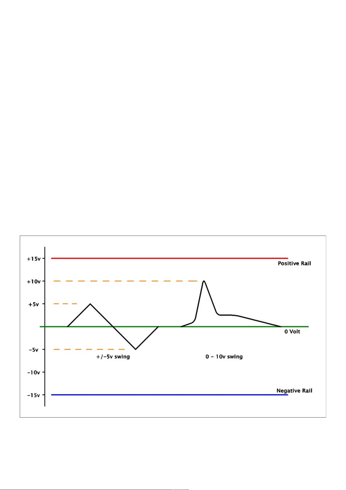
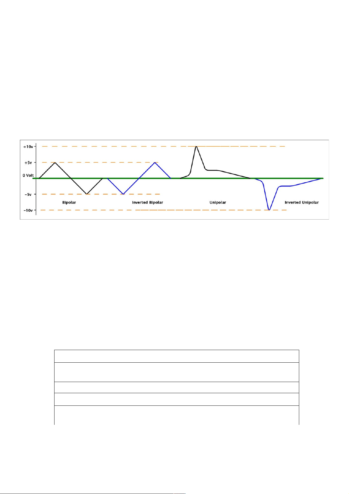
The Envelope Output is unipolar between 0V and +10V
with an exponential shape.
The Mode can be set as:
–Gated – Attack/Sustain/Release
When a gate occurs, the Envelope Output ramps up
to +10V at a rate determined by Attack and sustains
at that level until the gate ends, at which point it
releases at a rate determined by Decay.
If the Attack phase has not completed by the time
the gate ends, the Release phase starts immediately
without reaching +10V.
If a new gate occurs during Release phase, the
envelope starts rising again without resetting to 0V.
–Triggered – Attack/Decay
When a gate occurs, the attack phase is triggered
and the output rises to +10V before immediately
entering the decay phase.
It is only the rising edge of the gate that is of importance – if any further gates occur during
the attack phase, they are ignored, while a gate during the decay phase changes the envelope
back into attack phase without resetting to 0V.
–Loo
The output continuously oscillates between 0V and +10V. Any gate inputs behave like in
Triggered mode – ignored during attack, triggered to attack (without reset) during decay.
The Fast range offers audio rates, primarily for use in Loop mode, while the Slow(er) range offers
sub-audio rates for more typical Envelope usage. Note that faster Attack/Decay rates are achieved
by turning the dials clockwise – this may seem counter-intuitive, but makes more sense if thinking
of it raising the frequency of an oscillator.
Fast – Atk 34 mS – 60 μS Dcy 50mS – 90 μS
Slow - Atk 3.5 S – 5 mS Dcy 5 S – 8 mS
Slower - Atk 15 S – 22 mS Dcy 25 S – 35 mS
Rates can be further expanded downwards by patching a fixed DC voltage (eg. -5V) to any CV input.
Patch Ideas
Oscillator Overtones – Set Mode to Loop, Range to Fast and feed a VCO to the Gate Input.
With Attack turned fully clockwise, adjust Decay to hear Sync Waves. Works at LFO rates too.
Sub-Oscillator / Clock-Divide – Set Mode to AD, Range to Fast and feed a VCO to the Gate.
With Decay turned fully clockwise, adjust Attack to hear audio sub-divisions. Works at LFO rates.
Envelo e Sha e Bending – By patching the Envelope output back into the CV inputs, you can bend
the envelope shape into more linear or logarithmic shapes (note - also changes the frequency).
There are no internal adjustment arameters for this module.

Compact VCO
Built around a Triangle-Core Oscillator with waveshapers, this module is
designed as a small and stable source of Voltage-Controlled waveforms at
audio (Osc) or sub-audio (LFO) rates.
The Frequency is determined by a summation of Tune (10 Oct Range), Fine
Tune (1 Oct Range), Octave Switch (-1/0/+1 Oct) and two Exponential CV
inputs – EFM (Exponential Frequency Modulation) with Polarizing
Attenuator and precision 1V/Oct input.
Ranges [with Fine Centred, Octave Switch centred]:
–Osc approx. 20 Hz to 20 kHz
–LFO 40 mHz (25 S) to 50 Hz
The output Waveform Shape can be manually swept from Triangle or Double
Frequency Triangle to Saw-Tooth or Square dependent on the switches.
All waveforms are bipolar +/-5V.
The Sync input resets the Triangle to 0V whenever the input rises above +1V
(via internal comparator). The waveform may then move in either an
upwards or downwards direction (dependent on where in the waveform
charging cycle the Sync occurs). The waveform diagram shows where the
Triangle centre points correspond to for the other waveforms.
The bicolour LED indicates the Triangle wave.
Patch Ideas
Self-modulation – patch the Wave output back into the EFM CV input. Waveforms are skewed as
positive or inverted modulation is brought in – Tri/Saw produce
Log/Exp shapes, while Sqr produces different pulse-widths. Note
that it will alter the frequency.
Cross-modulation – patch the Wave output from one VCO into the
EFM CV input of a 2nd VCO and the Wave output from the 2nd into
the 1st one s EFM CV input. Experiment with rates and depths.
Something approaching tuned noise can be achieved when both
EFM depths are set to maximum.
Calibration
The three VCO modules are tuned together during calibration to
track 1V/Oct at around +/-1 cent over at least a 5 octave range.
Any user calibration should be performed with caution, a fine
touch and care to avoid adjusting the wrong parameter. Let the
unit warm up for 1 hour before adjusting the tracking. All trimmers
are multi-turn and require adjustment with a small flat-head
screwdriver.
Trimmers from top to bottom:
Offs – adjusts the base frequency of operation – preset to make lowest Osc Tune setting to 20 Hz.
Scale – adjusts the 1V/Oct tuning response.
HFTrm– adjusts the High Frequency tracking response for the 1V/Oct tuning.
RmpOffs – nulls the switching error glitch at the centre of the Saw wave.
+1V – adjusts the +1 Octave setting
-1V – adjusts the -1 Octave setting

Dual Filter
This module offers a pair of State-Variable Filters with
Low, Band or High Pass responses and variable Resonance
up to self-oscillation. The Filters are largely identical
except that the left-hand one features a range switch while
the right-hand one offers output phase inversion.
Each Filter has a DC-coupled Input typically expecting a
bipolar +/-5V input signal. The Output is also DC-coupled,
with in-phase unity gain when no filtering or resonance are
applied.
The Low and High pass responses are 2-pole 12dB/Oct,
while the Band pass is 1-pole 6dB/Oct.
The Cutoff Frequency is determined by a sum of the
Frequency dial and the two Exponential Control Sources –
CV A via Polarizing FMod Attenuator and V/Oct.
With Resonance turned up full, the Filters will self-
oscillate, producing a pure sine-wave which will track over
several octaves via the V/Oct input. Note that the
oscillation amplitude increases with frequency:
20 Hz – 3V P-to-P, 200 Hz – 4V P-to-P,
2 kHz – 6V P-to-P, 12 k Hz – 8V P-to-P,
The Sub mode on the left-hand section switches in extra filter capacitors to shift the range into sub-
audio frequencies.
Low-pass corresponds to integration and functions like a Voltage-Controlled Glide when resonance
is set to minimum.
High-pass corresponds to differentiation and can create variable exponential decay (instant attack)
envelopes from a Squarewave input.
[Who knows what the Band-pass corresponds to.?. experiment]
Adding resonance will cause oscillations to be superimposed on the resulting waveform – akin to
waveform wobble, it gives strange results in the VC-Glide areas.
The output will oscillate as in Audio mode, though you may need to turn the frequency up first to
allow oscillations to build up to full amplitude.
The Phase switch on the right-hand section is a simple polarity inverter for the Main Path output.
You can experiment with the switch while mixing (externally) the input/dry signal with the Filter
output.
Calibration
Note that the module is not temperature compensated and that best tracking stability is achieved
after around 2 hours warm-up time.
Each filter has a multi-turn trimmer to adjust the V/Oct response.

Dual Ampli ier
The basis of the module is a pair of DC-coupled Voltage-
Controlled Amplifiers (or, more accurately, attenuators –
gain is variable from 0 to +1) each with a form of
waveshapping which can be switched in to follow each
VCA. The Initial controls sweep the VCAs from fully closed
to fully open.
The left-hand unit features a Linear response and two
Main Path inputs – one full scale (In A) and one with
attenuator (In B) allowing two inputs to be mixed.
The Fold switch brings in a 4-stage Wavefolder which folds
the waveform tips back in on themselves as amplitude is
increased [does not work with squarewaves!] resulting in
extra harmonics.
The Fold mode works fine with sub-audio signals and
folding kicks in around 9 o clock on the Initial dial.
Try mixing a sub-audio signal into In B while running an
audio signal into In A for a width modulation effect.
A passable white-noise source can be made by patching the
Out to In A and turning the Initial dial up to near full.
The right-hand unit has only one Main Path input (again
DC-coupled), but the response can be swept between
Linear and Exponential which gives a sharper response from envelope modulation. It also features
a 2nd unattenuated modulation input.
The Sat(uration) switch brings in an amplification stage with zener limiting at +/-5V. Soft-clipping
begins to occur after around 9 o clock on the Initial dial.
A 4 quadrant multiplier (Ring Modulator) can be patched using the two sections combined with the
DC Mixer.
•Switch both to VCA mode with Initial control set to around mid point
•Feed the same signal (carrier) to each side (In A and In)
•Feed a bipolar signal (modulator) to the centre CV inputs (CV and CV A) but set them to
opposing modulation depths (one fully clockwise, one fully anti-clockwise)
•Take the two Out signals to the DC Mixer and combine them with one inverted
•Tweak the Initial dials to minimise carrier and modulator bleed-through
There are no internal adjustment arameters for this module.

Dual Mixing
This module combines two different forms of utility mixer
– a two channel DC summing mixer and a three channel,
two bus output mixer.
The DC Mixer section takes two DC-coupled inputs, passes
them through polarizing attenuators before summing
them to the DC-coupled output. This section is useful for
scaling and combining control signals, but can equally be
used for audio signals.
The Output Mixer has three DC-coupled inputs which feed
two separate summing buses via individual Level controls.
Both 1/4” outputs are AC-coupled and are Impedance
Balanced. The lower Main sum features an extra Master
level control before output, while the Sub sum passes out
at full amplitude.
This arrangement allows signals to be output either to
independent destinations or in a stereo arrangement (set
Main Master to full).
Internal jumpers can be set to attenuate the two outputs
independently by approximately 12dB if required.

System Speci ications
External Supply Voltage: +12V DC, 1.5A (per Frame), 2.1mm, centre-positive, polarity and
over-current protected
Internal System Voltage: Bipolar +/-15V, 500mA per rail per frame
Power Bus Connections: 4 Way MTA100, 5” power cables
Wave orm Voltages: 10V peak-to-peak (unipolar 0-10V or bipolar +/-5V)
Gate Input Threshold: approx. +1V
Main Path Input Impedance: 30K Ohm Typical
Control Input Impedance: 100K Ohm Typical
Output Impedance: 470 Ohm Typical
Signal Connections: 4mm Banana Socket, Impedance Balanced 1/4” socket
Module Size: Frac Rack Standard
Modules are measured in multiples of FracWidth (FW) with 1FW being 1.5” width.
Modules are 5.25” tall (3 rack unit) and a maximum of 1.65” deep.
Module Fixing: M3 x 10mm Bolt.
The Frame Chassis and PCB Panels are all connected to Chassis 0V which joins the System 0V by
the DCDC converter.
Thanks to Palle Dahlstedt for his diverse and detailed observations during beta-testing.
And to the old-blue crew for allowing me to bounce ideas off them for the last few years.
Guarantee
The SynthVoice comes with a 2 year reasonable warranty. If any mechanical or electronic failure
occurs within the period, I will repair the fault free of charge. This excludes failure from
maltreatment or modification and any cosmetic degradation. Contact should first be made via
email to discuss the problem. Shipping to return the device is paid by the user and I cover return
shipping. Failures that are not covered by this guarantee may be fixed at standard rates.
Table of contents
Other BugBrand Music Equipment manuals