CTL1 – Touch Panel
Rev1 – Jan2010
Overview
The CTL1 Touch Panel combines a 4-Key Touch Controller with rows of a 4-Stage Preset Sequencer. The Touch
Pads generate individual CV Pressure Outputs, plus a Common Pressure and Common Gate. The active step of the
Preset Sequencer is selected either by using the Touch Pads and Step Input.
Controls
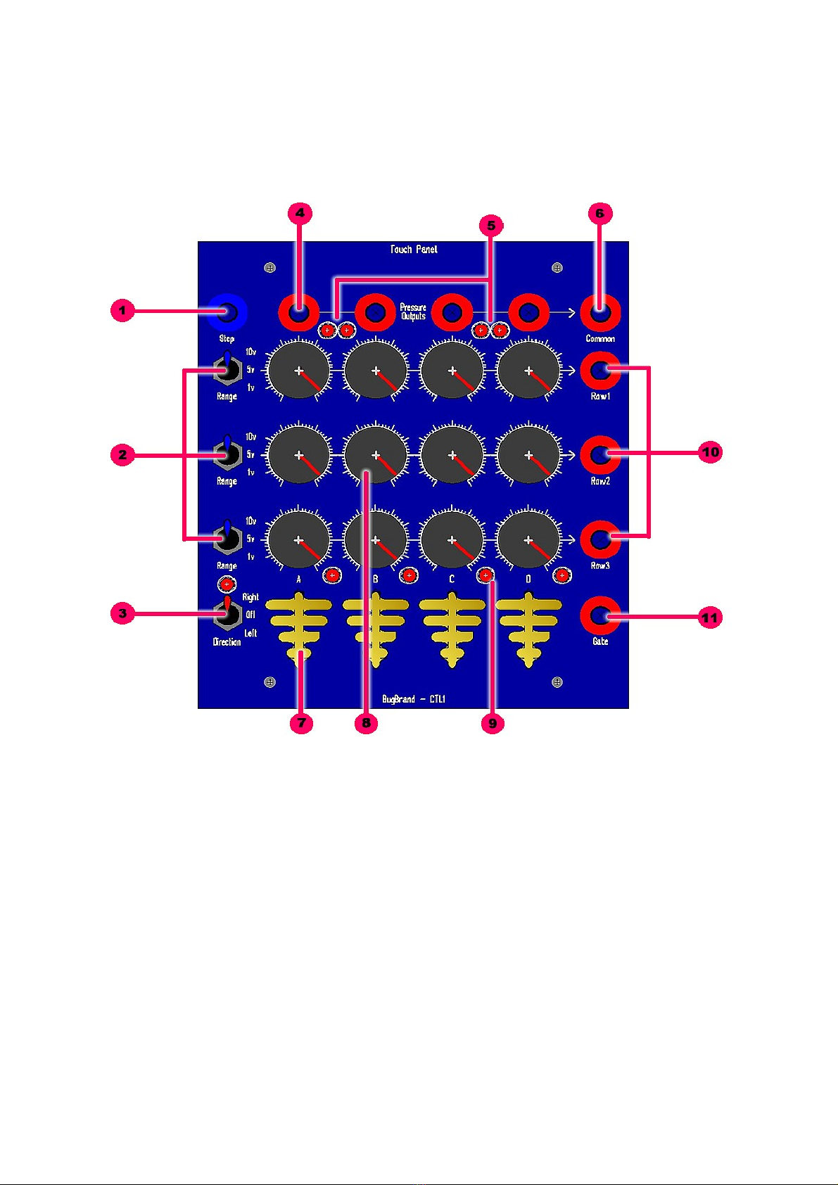
1. Step Input – Any voltage over c.+1.5v will clock the Preset Seq stage selection [dependent on Direction
Switch]. While a gate / clock signal may typically be used, any waveform that rises above 1.5v will work.
2. Row Range Switches (1 – 3) – Individual range selection switches for the three Rows – 10v, 5v, 1v.
(Voltage levels are preset on the rear of the module)
3. Direction Switch – Activates the Preset Seq clocking and selects left or right shifting of the active stage.
4. In ivi ual Pressure CV Outputs (A – D) – Key Pressure voltage outputs for the four individual keys.
Output range is 0v (inactive) to +10v maximum. (Pressure response is preset on the rear of the module)
5. In ivi ual Pressure LEDs (A – D) – Indication of the Pressure voltage outputs.
6. Common Pressure CV Output – Summed output of all four Key Pressure voltages (0-10v range)
7. Touch Pa s (A – D) – In general the keys respond in a monophonic way (ie. Press one key at a time).
When pressing a key the selected stage is 'held' (ie. Clocking is deactivated)
8. Preset Dials – Three rows and four stages to set Row Output voltages. Only one stage is active at any
time, but the three rows are independent.
9. Stage Active LEDs (A – D) – Showing the active Preset stage.
10. In ivi ual Row CV Outputs (1 – 3) – Outputs for the three rows with range governed by the individual
range switches.
11. Gate Output – The gate output goes high (+5v) whenever any touch pad is pressed. When not pressed the
gate output is 0v.


