Buhler FF-HM-230 User manual

Analysentechnik
Installation and Operation Instructions
Original instructions
Moisture detector controllers
Type FF-
BE410002
09/2017
Bühler Technologies GmbH, Harkortstr. 29, D-40880 Ratingen
Tel. +49 (0) 21 02 / 49 89-0, Fax: +49 (0) 21 02 / 49 89-20
E-Mail: [email protected]
Internet: www.buehler-technologies.com

Bühler Technologies GmbH, Harkortstr. 29, D-40880 Ratingen
Tel. +49 (0) 21 02 / 49 89-0, Fax: +49 (0) 21 02 / 49 89-20
Internet: www.buehler-technologies.com
E-Mail: [email protected]
Read this instruction carefully prior to installation and/or use. Pay at-
tention particularly to all advises and safety instructions to prevent in-
juries. Bühler Technologies can not be held responsible for misusing
the product or unreliable function due to unauthorised modifications.
All rights reserved. Bühler Technologies GmbH 2017
Document information
Document No..........................................................BE410002
Version......................................................................... 09/2017

Type FF-
Contents
1 Introduction..................................................................................................................................................................................................................... 2
1.1 Intended use .........................................................................................................................................................................................................2
1.2 Types .......................................................................................................................................................................................................................2
1.3 Contents................................................................................................................................................................................................................. 2
2 Safety instructions......................................................................................................................................................................................................... 3
2.1 Important advice................................................................................................................................................................................................. 3
2.2 General hazard warnings .................................................................................................................................................................................4
3 Transport and storage .................................................................................................................................................................................................. 5
4 Installation and connection ........................................................................................................................................................................................6
4.1 Mounting...............................................................................................................................................................................................................6
4.1.1 Mounting of moisture detector and adapter ............................................................................................................................. 6
4.1.2 Mounting of detector-controller..................................................................................................................................................... 6
4.2 Electrical connections ........................................................................................................................................................................................6
4.2.1 Controller type FF-19............................................................................................................................................................................7
4.2.2 Controller type FF-HM .........................................................................................................................................................................7
4.2.3 Controller type FF-..-U......................................................................................................................................................................... 8
5 Operation and control ..................................................................................................................................................................................................9
5.1 Adjusting the sensitivity ...................................................................................................................................................................................9
6 Maintenance.................................................................................................................................................................................................................. 10
6.1 Replacement of fuses.......................................................................................................................................................................................10
7 Service and repair.......................................................................................................................................................................................................... 11
7.1 Spare parts and accessories ............................................................................................................................................................................11
7.2 Troubleshooting .................................................................................................................................................................................................11
8 Disposal............................................................................................................................................................................................................................12
9 Appendices......................................................................................................................................................................................................................13
9.1 Technical Data.....................................................................................................................................................................................................13
9.2 Dimensions ..........................................................................................................................................................................................................13
10 Attached documents....................................................................................................................................................................................................15
iBühler Technologies GmbHBE410002 ◦ 09/2017

Type FF-
1 Introduction
1.1 Intended use
A moisture detector is a device which signals moisture in the gas flow of a sample gas treatment system. Here the electrodes
separated by a gap are located inside the Gas flow.
The circuit devices Type FF analyse the moisture detector FF-3-N and FF-40. These devices allow the analysis of moisture ingress
in the sample gas detected by the moisture detector, and to trigger an alarm.
1.2 Types
These operating instructions apply to the following devices. Please refer to the nameplate to identify your model.
Moisture detector and mounting adapter
FF-3-N moisture detector with cable break detection
FF-40 moisture detector with cable break detection, max. pressure 40 bar
Type G flowcell in PVDF
Type S flowcell in stainless steel
Controllers Voltage Connectible moisture detectors
FF-HM-230 for rail mounting 230/115 V AC for one FF-3-N moisture detector or FF-40
FF-HM-24 for rail mounting 24 V DC for one FF-3-N moisture detector or FF-40
FF-19 19" rack 24 V DC for one FF-3-N moisture detector or FF-40
FF-1-U inside small casing 230/115 V AC for one or two moisture detectors FF-1
FF-3-U inside small casing 230/115 V AC for one FF-3-N moisture detector or FF-40
FF-3-U-2 inside small casing 230/115 V AC for two separate FF-3-N or FF-40
The functionality and operability is identical for all controllers. Differences in the pin assignment are indicated accordingly.
Please note: proper functionality can only be guaranteed when using the specified moisture detectors with the controllers.
1.3 Contents
– Product documentation
– Optional (varies by order)
2 Bühler Technologies GmbH BE410002 ◦ 09/2017
Type FF-
2 Safety instructions
2.1 Important advice
Operation of the device is only valid if:
– the product is used under the conditions described in the installation- and operation instruction, the intended application
according to the type plate and the intended use. In case of unauthorized modifications done by the user Bühler Technolo-
gies GmbH can not be held responsible for any damage,
– when complying with the specifications and markings on the nameplates.
– the performance limits given in the datasheets and in the installation- and operation instruction are obeyed,
– monitoring devices and safety devices are installed properly,
– service and repair is carried out by Bühler Technologies GmbH,
– only original spare parts are used.
This manual is part of the equipment. The manufacturer keeps the right to modify specifications without advanced notice. Keep
this manual for later use.
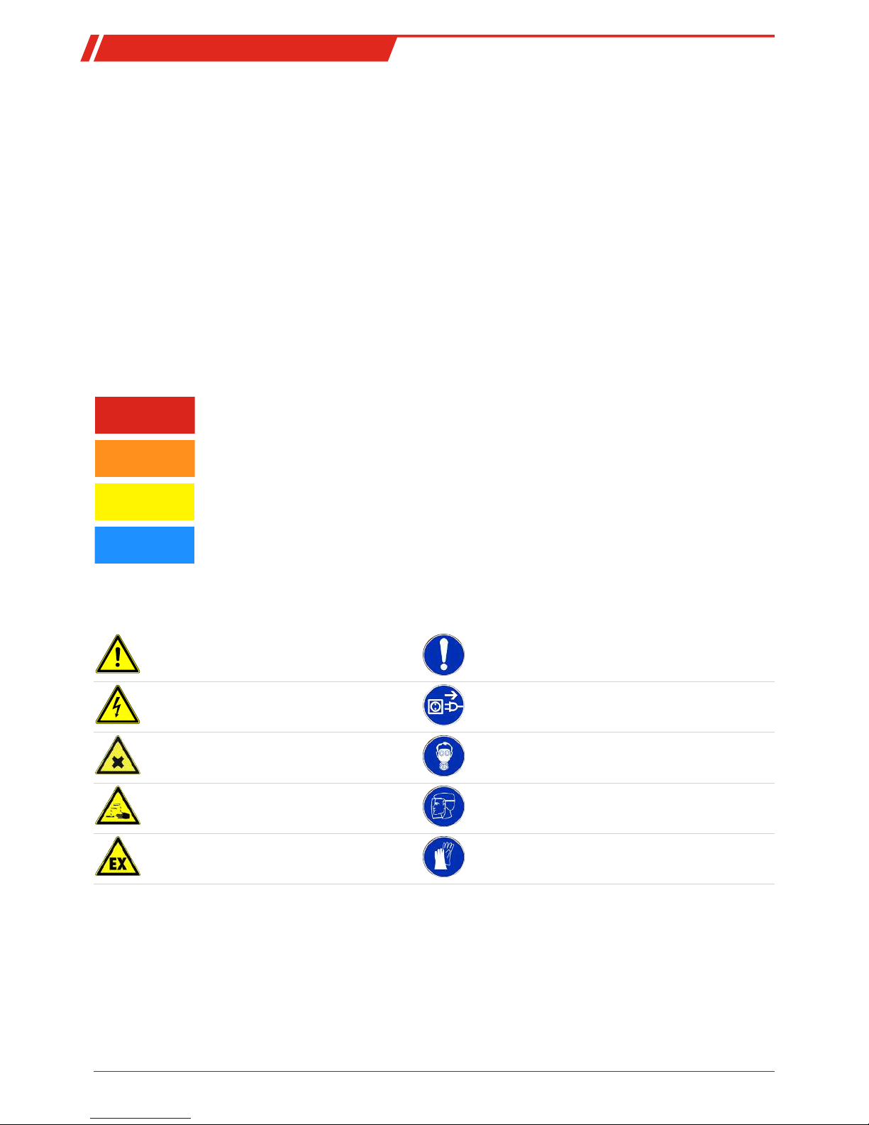
Signal words for warnings
DANGER
Signal word for an imminent danger with high risk, resulting in severe injuries or death if not avoided.
WARNING
Signal word for a hazardous situation with medium risk, possibly resulting in severe injuries or death if not
avoided.
CAUTION
Signal word for a hazardous situation with low risk, resulting in damaged to the device or the property or
minor or medium injuries if not avoided.
NOTICE
Signal word for important information to the product.
Warning signs
These instructions use the following warning signs:
Warns of a general hazard General information
Warns of voltage Unplug from mains
Warns not to inhale toxic gasses Wear respiratory equipment
Warns of corrosive liquids Wear a safety mask
Warns of explosive areas Wear gloves
3Bühler Technologies GmbHBE410002 ◦ 09/2017

Type FF-
2.2 General hazard warnings
The equipment must be installed by a professional familiar with the safety requirements and risks.
Be sure to observe the safety regulations and generally applicable rules of technology relevant for the installation site. Prevent
malfunctions and avoid personal injuries and property damage.
The operator of the system must ensure:
– Safety notices and operating instructions are available and observed,
– The respective national accident prevention regulations are observed,
– The permissible data and operational conditions are maintained,
– Safety guards are used and mandatory maintenance is performed,
– Legal regulations are observed during disposal.
Maintenance, Repair
Please note during maintenance and repairs:
– Repairs to the unit must be performed by Bühler authorised personnel.
– Only perform conversion-, maintenance or installation work described in these operating and installation instructions.
– Always use genuine spare parts.
Always observe the applicable safety and operating regulations in the respective country of use when performing any type of
maintenance.
DANGER Electrical voltage
Electrocution hazard.
a) Disconnect the device from power supply.
b) Make sure that the equipment cannot be reconnected to mains unintentionally.
c) The device must be opened by trained staff only.
d) Regard correct mains voltage.
DANGER Toxic, corrosive gases
The measuring gas led through the equipment can be hazardous when breathing or
touching it.
a) Check tightness of the measuring system before putting it into operation.
b) Take care that harmful gases are exhausted to a save place.
c) Before maintenance turn off the gas supply and make sure that it cannot be turned
on unintentionally.
d) Protect yourself during maintenance against toxic / corrosive gases. Use suitable pro-
tective equipment.
DANGER Potentially explosive atmosphere
Explosion hazard when used in explosive areas
The equipment is not suitable for use in explosive areas.
Never operate moisture detectors located in flammable or explosive gas mixtures on the
device.
4 Bühler Technologies GmbH BE410002 ◦ 09/2017

Type FF-
3 Transport and storage
The device should be only transported in the original case or in appropriate packing.
If the device is not used for some time, protect it against heat and humidity. Store the device in a roofed, dry, and dust free
room. Temperature should be between –20 °C and 40 °C (-4 °F and 104 °F).
5Bühler Technologies GmbHBE410002 ◦ 09/2017
Type FF-
4 Installation and connection
4.1 Mounting
4.1.1 Mounting of moisture detector and adapter
The flow adapter is equipped with internal threading, G1/4 or NPT1/4 (flow adaptor marked with NPT), for the gas connections
and G1/4 for the moisture sensor. The drawing you find on the backside of the attached data sheet. As well the fittings as the
moisture detector must be used with Teflon sealing or an O-ring to assure proper sealing of the sample stream. Please assure
that the wires are guided tension free.
If there’s particulate or aerosols in the sample gas, a filter has to be installed upstream the detector. Otherwise the particulate or
aerosols can build a layer on the detectors surface inhibiting its function.
The wire should NOT be put into one cable channel with power switching cords. The function can be influenced otherwise.
It might be necessary to adjust the position of the humidity sensor in strongly fluctuating ambient or component temperatures
in order to ensure the necessary tightness in the system.
4.1.2 Mounting of detector-controller
Controller type FF-19
This type is designed as an insert for 19"-housings. The bus connector is a DIN 41612 type B. Used pins of columns a and c are
plated through.
Before inserting the FF-19 into the housing, set the jumpers.
Controller types FF-HM
The type FF-HM is designed for standard 35 mm rail mounting according to DIN EN 50022.
Controller types type FF-..-U
For mounting disassemble the cover by loosening the 4 black screws. The holes for the mounting screws are below the black
screws. Mounting dimensions are 165 mm x 79 mm (6.5" x 3.1"). They are made for screws M4, the screws head should be at least
6 mm (0.24") in diameter.
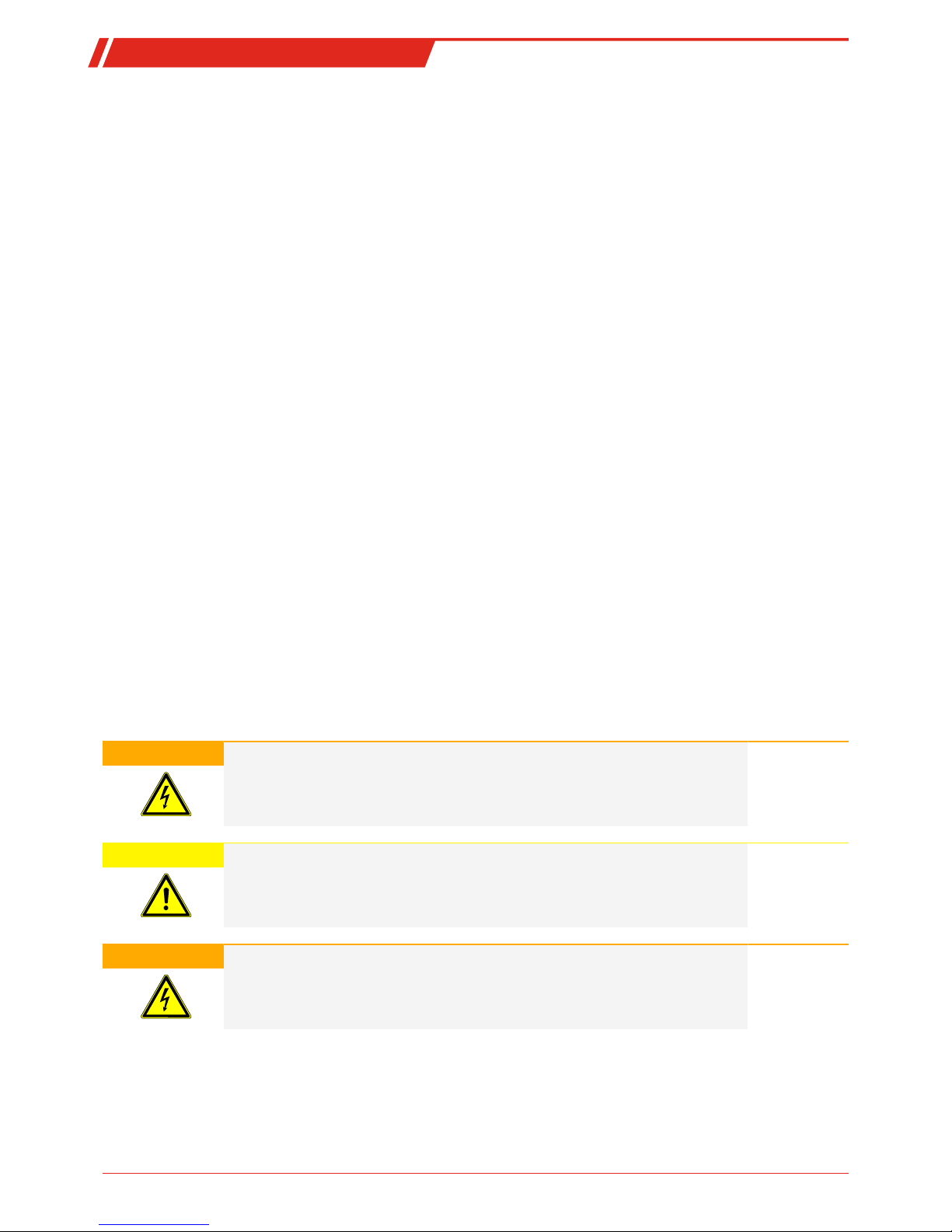
4.2 Electrical connections
WARNING Hazardous electrical voltage
The device must be installed by trained staff only.
CAUTION Wrong mains voltage
Wrong mains voltage may damage the device.
Regard the correct mains voltage as given on the type plate.
WARNING High voltage
Damage to the device in case of insulation testing
Do not proceed insulation tests with high voltage to the device as a whole!
6 Bühler Technologies GmbH BE410002 ◦ 09/2017

Type FF-
Insulation test
The device is equipped with extensive EMC protection. If insulation tests are carried out the electronic filter devices will be dam-
aged. All necessary tests have been carried out for all concerned groups of components at the factory (test voltage 1 kV or 1.5 kV
respectively, depending on the device).
Moisture and broken-wire alarms are signaled via two independent dry contacts.
They are made fail-safe in the FF-HM and FF-19 types: The relays switch when power is turned on and no moisture is detected,
they fall off when power fails, moisture or a broken wire is detected. Relays are used in the opposite logic with the types FF-..-U
(switched in the alarm case).
The devices have three LEDs (FF-3-U-2: five LEDs) for POWER, BROKEN WIRE and MOISTURE.
Alarms are monostable; they switch back after the cause for the alarm is removed.
Using the FF-HM or FF-19 type a hold function can be chosen by setting/wiring a jumper. The alarm will stay until the internal or
externally connected reset button is pressed.
4.2.1 Controller type FF-19
Note the drawing 47/075-06-4.
This type can only be used with a 24 V DC power supply. NOTICE!The grounding to PE has always to be attached!
The detector FF-40 is connected to PIN 30 and 31, the shield to PIN 2.
Connect the cable to the FF-3-N. Root strands white and brown to PIN 30 and 31, and shielding to PIN 2.
For FF-3-N and FF-40 the jumper J2 is set to 2-3.
When using older models (FF-1) jumper J2 has to be set to 1-2. Otherwise the controller would signal a broken wire.
Alarm hold function:
To select this function, jumper J1 has to be set to 2-3. An external reset switch or contact can be connected to PIN 26 and 27 of the
bus connector.
NOTICE!When using a detector without broken wire-detection, the broken wire alarm is not used. The relay contact may then
be used to look for power supply failure.
When installing the FF-3-N or FF-40 detector, both relays are used. A power supply failure may be seen by combining both alarm
outputs with an AND function since in working condition EITHER moisture alarm OR broken wire alarm is given.
4.2.2 Controller type FF-HM
Note the drawing 41/073-01-4 and 41/074-01-4.
On the upper terminal are the connections for power supply and alarm relay outputs, on the lower terminal the moisture de-
tector and the external reset switch are connected.
The type FF-HM-230 is suitable for 230 V AC and 115 V AC. The jumpers are factory set to 230 V AC. To change it to 115 V AC discon-
nect the jumper between terminals 9-10 and set jumpers to terminals 8-9 and 10-11. The power supply is connected to terminals
12-13 (PE is 7).
The type FF-HM-24 is only suitable for 24 V DC. The power supply is connected to terminals 12-13. NOTICE!Even with this control-
ler, PE has always to be connected to terminal 7!
Connecting the moisture detector:
The detector FF-40 is connected to terminals 25-26, the shield to 24.
Connect the cable to the FF-3-N. Root strands white and brown to terminals 25-26, and shielding to terminal 24.
When using models FF-3-N and FF-40, terminals 22 and 23 stay open to ensure broken wire detection.
When using older models (FF-1), a jumper must be set between terminals 22 and 23.
Hold function:
To enable this function, a jumper has to be set between terminals 20 and 21. An external reset switch or contact may be connec-
ted to terminals 14 and 15. The shield of this wire is connected to terminal 16.
7Bühler Technologies GmbHBE410002 ◦ 09/2017

Type FF-
NOTICE
To prevent malfunction, the wires to the reset switch have to be shielded!
4.2.3 Controller type FF-..-U
Note the drawing 41/065-07-4.
After opening the housing you will see the switch for the voltage adjustment next to the fuses, which must first be set to your
voltage.
The power supply is connected directly next to the switch (refer to board labelling).
The moisture detector for protective elements FF-3-U-2 and FF-1-U attach to the 5-pin terminal X3 with the white and brown con-
ductors according to the connection diagram. On protective element type FF-3-U the moisture detector attaches to the 3-pin ter-
minal X3. Connect the shielding with care.
The signal relay for Type FF-3-U and FF-1-U connect to the 6-pin terminal above the switch, on Type FF-3-U-2 they connect to a 12-
pin terminal. Please also refer to the connection plans FF-U in the appendix.
Please be sure to sufficiently tighten the screw connections.
NOTICE!With these types both output relays will trigger in the event of a cable break, so also that of the moisture alarm.
8 Bühler Technologies GmbH BE410002 ◦ 09/2017
This manual suits for next models
5
Table of contents
Other Buhler Security Sensor manuals


