manuals.online logo
Brands
  1. Home
  2. •
  3. Brands
  4. •
  5. Siemens
  6. •
  7. Security Sensor
  8. •
  9. Siemens AZL66 Series User manual

Siemens AZL66 Series User manual

CC1N7560en
12/20/2019
Smart Infrastructure
7562
Display and operating
units
AZL66…
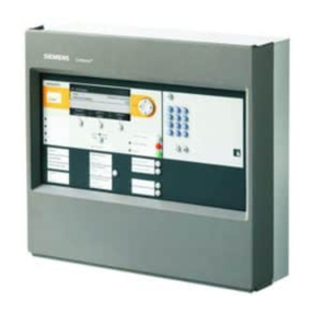
AZL66 display and operating units are used in connection with the LMV6 burner
management system directly on the burner or in control cabinets within the
burner's immediate vicinity.
AZL66 units are used for the display, operation, and parameterization of
specific safety-related and non-safety-related burner functions.
Key plant data and fault codes can be queried and displayed.
Communication between the AZL66 and the LMV6 takes place via the CAN
interface.
The AZL66 and this data sheet are intended for original equipment manufacturers
(OEMs) using the AZL66 in or on their products.
2/14
Smart Infrastructure CC1N7562en
12/20/2019
Use / Features
The description that follows reflects the maximum functional scope of the AZL66.
The actual functions and the principle of operation are to be determined based on the
LMV6.
Housing in a modern design featuring recycled plastic
Flame-retardant housing material
Display of operating states, program phases, and fault codes
Setting of parameters and ratio control curves
Separate unit for front-panel installation
With 4.3" TFT display
With push-turn controller as central setting element
With 2 additional buttons
Many languages possible
With USB port
With LED to visualize the status of the burner
Back-lit LCD (support dependent on LMV6)
Fault display via an LED
Backup function
Housing designed for panel cut-out mounting (IP54 degree of protection when
installed)
Supplementary documentation
Product type Type of documentation Documentation numbe
r
LMV60.110A2 User Documentation A7560.1
Data Sheet N7560
Basic Documentation P7560
Environmental Declaration E7560 *)
AZL66 User Manual U7562
Environmental Declaration E7562 *)
*) On request only
Warning notes
You will find additional safety instructions in the corresponding documentation
for the LMV6.
To avoid personal injury or damage to property or the environment, the following
warning notes must be observed.
3/14
Smart Infrastructure CC1N7562en
12/20/2019
Notes on product liability
AZL66 units may only be used in building services plant and only in compliance
with the applications described in this document.
Compliance with all requirements described in the following chapters is a
mandatory condition for using the AZL66.
Local safety regulations (installation, etc.) must be complied with.
It is not permitted to open AZL66 units. The warranty obligation shall become void
if this requirement is violated.
Caution
It is not permitted to open, interfere with, or modify the AZL66.
All activities (mounting, installation, service work, etc.) must be performed by
qualified staff
Before carrying out any wiring changes in the connection area, isolate the plant
from the power supply (all-pole disconnection). Ensure that the plant cannot be
inadvertently switched on again and that it is indeed dead. Failure to observe this
information poses a risk of electric shock
Take suitable measures to provide protection against accidental contact at the
electrical connections. Failure to observe this information poses a risk of electric
shock
On completion of every task (mounting, installation, service work, shutdown, etc.)
always check that the CAN interface is wired and connected correctly (RAST3.81
jack) in the AZL66 housing and that the parameter settings have been made
correctly. Failure to observe this information poses a risk of damaging the safety
functions and a risk of electric shock
These AZL66 units must not be put into operation following impact or shock; even if
they do not exhibit any visible damage, their safety functions may be impaired.
Failure to observe this information poses a risk of damaging the safety functions
and a risk of electric shock
The burner or boiler manufacturer must ensure degree of protection IP40 / IP54 for
the LMV6 and AZL66 as per DIN EN 60529. Failure to observe this information
poses a risk of damaging the safety functions and a risk of electric shock
Siemens does not assume responsibility for damage resulting from unauthorized
interventions.
Electromagnetic emissions must be checked on an application-specific basis!
Only qualified personnel are allowed to start up and operate the AZL66. Qualified
personnel in the context of the safety-related notes contained in this data sheet are
persons who are authorized to commission, ground, and tag units, systems, and
electrical circuits in compliance with established safety practices and standards.
Note the following:
The AZL66 may only be used for the applications described in the technical
documentation and only in connection with Siemens burner management systems.
The AZL66 can only function correctly and safely if shipped, stored, set up, and
installed correctly, and operated and maintained with care.
Qualified personnel
Correct use
4/14
Smart Infrastructure CC1N7562en
12/20/2019
Mounting notes
Ensure that the relevant national safety regulations and notes on standards are
complied with
Please note that the mounting surface must be completely flat
The AZL66 must be used in a dry and clean environment
Note the tightening torque of 0.5 Nm; this is a condition for compliance with IP54
Step 1 Position the AZL66 in the correct place
inside the designated opening (do not
apply excess pressure).
Step 2 Next, screw the AZL66 tight with the
countersunk cross-head screws in the
housing (do not apply excess pressure).

Note!
If the AZL66 does not fit inside the
designated opening, check the cut-out
and the housing.
The AZL66 units are manufactured with installation dimensions of 90.1 x 125.7 mm
0.5. The dimensions of the front panel result in a grid dimension of 90.5 mm. The
mounting mechanisms enable the ALZ66 units to be installed in front panels of various
thicknesses (1–3 mm).
Please note that the mounting surface must be completely flat
The M4 screws with O-rings (such as those similar to 10-UNF) are equipped with a
swivel bolt lock and are included in the scope of delivery of the AZL66
Panel cut-out mounting of the
AZL66
Cut-out dimensions
for the AZL66
5/14
Smart Infrastructure CC1N7562en
12/20/2019
Operating philosophy / Display philosophy
The operating philosophy and display philosophy can be found in the relevant user
manuals for the LMV6. All unit versions of the AZL66 function and are operated in the
same way.
Graphics Function Function
None Rotary knob
TURN
Navigate through tile views or list views
Can be turned clockwise to the right or down
Can be turned counterclockwise to the left or up
Change parameter values
None Rotary knob
ENTER
Select a tile / menu item
Confirm a change to a parameter value
Acknowledge messages
Back
(Return) Exit a tile / menu item / value adjuster without making further changes
Menu Jump to the top level of the menu tree (possible from anywhere)
Access to additional functions (if available)
6/14
Smart Infrastructure CC1N7562en
12/20/2019
Meaning of symbols on the display
Tile Meaning
Changing parameters
Entering burner-specific parameters
Adaptation of programs and/or components/accessories to the
LMV6 and adaptation of the LMV6 to its
components/accessories.
Central repository of all relevant parameters for commissioning
Maintenance prompt message. Maintenance is carried out at
regular intervals by trained specialist personnel. The most
important information required by the heating engineer to carry
out maintenance is stored here.
Repository for error and fault history
Entering the password
Changing the language (default: English)
7/14
Smart Infrastructure CC1N7562en
12/20/2019
Installation notes
AGG6.635 signal cable from the LMV6 to the AZL66. The AGG6.635 signal cable
is specified for use under the burner hood. If other signal cables are used, there is
no guarantee that the required cable features will be available.
Lay the AGG6.635 signal cable from the LMV6 to the AZL66 separately from other
cables.
Both the AGG6.635 signal cable and the AZL66 must be shipped and stored so
that no damage due to dust and water can occur during subsequent use in the
plant.
Prior to switching on the mains voltage, make certain that the AGG6.635 signal
cable has been connected to the AZL66 correctly.
The AZL66 must be used in a dry and clean environment.
The electrical power supply must be disconnected prior to installation.
The requirements of protection class II must be observed for the wiring.
Static charges must be avoided since they can damage the electronic components
of the AZL66 on contact.
Recommendation: Use ESD equipment!
Caution
DIN EN 60335 and DIN EN 60730-2-5 must be complied with
Ensure that the electrical wiring inside the boiler complies with national and local
regulations.
The burner or boiler manufacturer must ensure degree of protection IP40 / IP54
for the LMV6 and AZL66 as per DIN EN 60529. Failure to observe this
information poses a risk of damaging the safety functions and a risk of electric
shock
8/14
Smart Infrastructure CC1N7562en
12/20/2019
Commissioning notes
The burner or boiler manufacturer is responsible for parameterizing the LMV6 correctly;
this involves compliance with the relevant standards and guidelines.
Standards and certificates
Note!
Only in connection with the LMV6!
ISO 9001:2015
ISO 14001:2015
OHSAS 18001:2007
China RoHS
Hazardous substances table:
http://www.siemens.com/download?A6V10883536
Disposal notes
The AZL66 contains electrical and electronic components and must not be disposed of
together with domestic waste. Local and currently valid legislation must be complied
with.
Prerequisites
9/14
Smart Infrastructure CC1N7562en
12/20/2019
Open Source Software (OSS) declaration
Due to the license terms of the software we use, Siemens AG wishes to note that the
OEM is obligated to provide the following license text for the end user in the
documentation:
Open Source Software (OSS) declaration
Embedded in – or bundled with – the AZL66 are open source software (OSS)
components and other third-party components identified below. You will find the
specific product type and the valid version in the OSS document.
Title: Readme_OSS AZL66 V01.
You may obtain, distribute, and/or modify a copy of the open source code for the
component under the terms of their respective licenses. These may be a GNU General
Public License, the GNU Lesser General Public License, a modified BSD license, or an
MIT license. In the event of conflicts between Siemens license conditions and the open
source software license conditions, the open source software conditions shall prevail
with respect to the open source software portions of the software.
You are permitted to modify proprietary components originating from Siemens and
make changes as part of a reverse engineering process for debugging purposes, to the
extent that these are linked to libraries licensed under the GNU Lesser General Public
License.
You are not permitted to distribute information resulting from this reverse engineering
process of from the modified proprietary components. Your rights to modify proprietary
components originating from parties other than Siemens are governed by the
respective third-party license conditions.
On written request within three years from the date of product purchase and against
payment of our expenses, Siemens will supply the source code for any OSS
component identified below in line with the terms of the applicable license.
Please contact us in this regard at:
Siemens AG
Otto-Hahn-Ring 6
81739 Munich
Germany
Reference: Open Source Request
The identified OSS components are generally distributed in the hope that they will be
useful, but WITHOUT ANY WARRANTY, without even implied warranty of
merchantability or FITNESS FOR A PARTICULAR PURPOSE, and without liability for
any Siemens entity other than as explicitly documented in your purchase contract.
All open source software components used within the product (including their copyright
holders and the license conditions) can be found on the website at
http://www.siemens.com/download?A6V11985972.
10/14
Smart Infrastructure CC1N7562en
12/20/2019
Type summary
Type AZL66.00A8
Article no. S55629-H301-A100
Functions
Graphic display (4.3" TFT with 480 x 272 pixels) ●
Parameter-setting functions and display functions ●
Saving of fault histories and error histories ●
Reset ●
Burner rapid shutdown using button combinations ●
3 access levels, 2 of which have password protection ●
Parameter backup function ●
11/14
Smart Infrastructure CC1N7562en
12/20/2019
Technical data
Supply voltage 24 V DC -15% / +10%
Power consumption < 5 W, typically
Degree of protection
Rear IP00 in accordance with DIN EN 60529
Front IP54 in accordance with DIN EN 60529
when installed
Protection class II in accordance with DIN EN 60730-1
Housing
Material PC and PC / ABS
Color RAL 7035 (light gray)
Flammability rating
Clear housing parts According to UL94 V2 (PC)
Dyed housing parts According to UL94 V0 (PC / ABS)
Weight Approx. 260 g
Pollution degree 2
Tightening torque for fixing screws Max. 0.5 Nm
Cut-out dimensions 90.1 x 125.7 mm 0.5
Signal cable White in color
Shielded
With RAST3.81 connector
Cable length 3 m
Place of installation Under the burner hood (arrangements for
SKII EN 60730-1 additionally required)
Connection Color Wire cross-section
in mm²
24 V DC 1 White 0.5
24 V DC 2 Brown 0.5
CANH Yellow 0.25
CANL Green 0.25
The permissible cable length is specified in the data sheet for the LMV6.
CAN interface with RAST3.81 jack To Siemens LMV6 burner management
system
General unit data
A
GG6.635 signal cable
Display BCI
Inputs/outputs
12/14
Smart Infrastructure CC1N7562en
12/20/2019
Technical data (continued)
Storage DIN EN 60721-3-1
Climatic conditions Class 1K3
Mechanical conditions Class 1M2
Temperature range -20 to +60°C
Humidity < 95% r.h.
Transport DIN EN 60721-3-2
Climatic conditions Class 2K3
Mechanical conditions Class 2M2
Temperature range -20 to +60°C
Humidity < 95% r.h.
Operation DIN EN 60721-3-3
Climatic conditions Class 3K3
Mechanical conditions Class 3M3
Temperature range -20 to +60°C
Humidity < 95% r.h.
Installation altitude Max. 2,000 m above sea level
Warning!
Condensation, formation of ice, and ingress of water are not permitted. Failure
to observe this information poses a risk of damaging the safety functions and a
risk of electric shock.
Environmental
conditions
13/14
Smart Infrastructure CC1N7562en
12/20/2019
Connection diagram
Example: Basic diagram of AZL66 with LMV6
Connection, AZL66 to
LMV6
14/14
Smart Infrastructure CC1N7562en
12/20/2019
Dimensions
Dimensions in mm
119,2
90,1
143,2
125,7
140
46,1
22,1
M1:2
7560m07/0319
A
ZL66
2019 Siemens AG Smart Infrastructure, Berliner Ring 23, 76437 Rastatt, Germany
Subject to change!

Other manuals for AZL66 Series

1

Other Siemens Security Sensor manuals

Siemens FDO421 User manual

Siemens

Siemens FDO421 User manual

Siemens DF11 Series User manual

Siemens

Siemens DF11 Series User manual

Siemens FDB22 Series User manual

Siemens

Siemens FDB22 Series User manual

Siemens Simotion TM 121C Instructions for use

Siemens

Siemens Simotion TM 121C Instructions for use

Siemens AlgoRex CS1140 Operating instructions

Siemens

Siemens AlgoRex CS1140 Operating instructions

Siemens QRI Series User manual

Siemens

Siemens QRI Series User manual

Siemens FDT181C User manual

Siemens

Siemens FDT181C User manual

Siemens FDT181 User manual

Siemens

Siemens FDT181 User manual

Siemens SIRIUS 3RK3 User guide

Siemens

Siemens SIRIUS 3RK3 User guide

Siemens AS Series User manual

Siemens

Siemens AS Series User manual

Siemens FDM243H User manual

Siemens

Siemens FDM243H User manual

Siemens LAE10 User manual

Siemens

Siemens LAE10 User manual

Siemens UP 258D11 OPTISENS OFFICE User manual

Siemens

Siemens UP 258D11 OPTISENS OFFICE User manual

Siemens Matchtec IRM270C User manual

Siemens

Siemens Matchtec IRM270C User manual

Siemens FDOOT271 Guide

Siemens

Siemens FDOOT271 Guide

Siemens FDL241-9 Quick start guide

Siemens

Siemens FDL241-9 Quick start guide

Siemens SO320 User manual

Siemens

Siemens SO320 User manual

Siemens RAR Series User manual

Siemens

Siemens RAR Series User manual

Siemens Cerberus DOTE1152 Parts list manual

Siemens

Siemens Cerberus DOTE1152 Parts list manual

Siemens FDOOT271 User manual

Siemens

Siemens FDOOT271 User manual

Siemens MSI-51B Technical specifications

Siemens

Siemens MSI-51B Technical specifications

Siemens 5TC1585 User manual

Siemens

Siemens 5TC1585 User manual

Siemens FDO421 User manual

Siemens

Siemens FDO421 User manual

Siemens DELTA i-system 1,1 Komfort 5TC1 505 User manual

Siemens

Siemens DELTA i-system 1,1 Komfort 5TC1 505 User manual

Popular Security Sensor manuals by other brands

Daihatsu MD-SX instruction manual

Daihatsu

Daihatsu MD-SX instruction manual

Leuze electronic MLC 500 Series SAFE IMPLEMENTATION AND OPERATION

Leuze electronic

Leuze electronic MLC 500 Series SAFE IMPLEMENTATION AND OPERATION

Baso L62AA installation instructions

Baso

Baso L62AA installation instructions

Blocklychain MD-104 instruction manual

Blocklychain

Blocklychain MD-104 instruction manual

koban KDT 8900 manual

koban

koban KDT 8900 manual

ABB Orion 3 Base Original instructions

ABB

ABB Orion 3 Base Original instructions

Honeywell FS24X Installation guide and operating manual

Honeywell

Honeywell FS24X Installation guide and operating manual

Johnson Controls tyco Bentel Security BW-DTM installation instructions

Johnson Controls

Johnson Controls tyco Bentel Security BW-DTM installation instructions

Simtronics MultiTox DGi-TT7-E operating manual

Simtronics

Simtronics MultiTox DGi-TT7-E operating manual

Interlogix GS960AM manual

Interlogix

Interlogix GS960AM manual

Protecta REBEL user manual

Protecta

Protecta REBEL user manual

Ortech OL-S instruction manual

Ortech

Ortech OL-S instruction manual

CARLO GAVAZZI RAD Series manual

CARLO GAVAZZI

CARLO GAVAZZI RAD Series manual

Endress+Hauser nivotester FTL 325 P operating instructions

Endress+Hauser

Endress+Hauser nivotester FTL 325 P operating instructions

Radon TEVISO RA14 Application notes

Radon

Radon TEVISO RA14 Application notes

PCB Piezotronics 4115K-02A Installation and operating manual

PCB Piezotronics

PCB Piezotronics 4115K-02A Installation and operating manual

ETC Unison Aero UARVSS-5 installation guide

ETC

ETC Unison Aero UARVSS-5 installation guide

Raven SID-20200 manual

Raven

Raven SID-20200 manual

manuals.online logo
manuals.online logoBrands
  • About & Mission
  • Contact us
  • Privacy Policy
  • Terms and Conditions

Copyright 2025 Manuals.Online. All Rights Reserved.