Build Equinox CERV2 User manual

CERV2 Zone Option Manual
Build Equinox
(773)-492-1893
Rev 1.3 - 11/03/2020
© Build Equinox 2020

2
Zone Damper Wiring
There are two ways to physically control the Zone Damper motors –With the CERV’s integrated X0 Auxiliary Output, or with the
optional IO Expansion Board. Both options require 3 conductor wire capable of carrying 24VAC at 0.5A (thermostat wire is
acceptable).
The standard damper motor terminal block is three positions, with the first as a common, while the second and third activate
the damper motor to turn clockwise or counterclockwise when voltage is applied. This may vary if other damper motors, such as
spring return, are used. Rotation of the damper motor can sometimes be confusing when wiring the terminals, so the damper
motor has an integrated switch to reverse the rotation direction. If you apply system power and find that the damper motor is
rotating the wrong way, you can simply toggle the switch with a small flathead screwdriver.
Integrated X0 Auxiliary Output
The terminal block for the X0 Auxiliary Output is located in the bottom section of the CERV2 (see appendix at end of document
for access instructions). Because the X0 is a standard dry contact with Normally Open (1), Common (2), and Normally Closed (3)
terminals, it must be used in conjunction with the 24VAC output terminals (4, 5) as seen above.

3
IO Expansion Board, X1-X6 Auxiliary Outputs
In addition to the integrated X0 Auxiliary output, the I/O Expansion Board is capable of directly outputting 24VAC through its
terminals without requiring connection to an external 24VAC source. NOTE: for this configuration, you must move the slide-
switch above the terminal block towards the 24VAC OUTPUT label. LED indicators on the I/O Expansion Board will light up above
either the NO or NC terminals, to indicate which is active. Up to six zone dampers may be connected to the I/O Expansion
Board. See the I/O Expansion Board manual for more information on installing and configuring the expansion board.

4
Touchscreen Zone Configuration
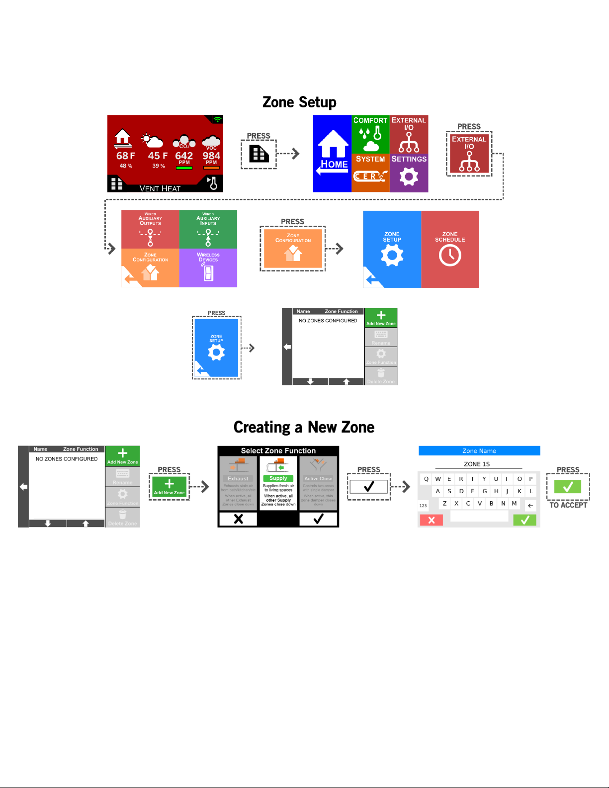
The first step in setting up your zone damper system is to define Zone areas. The following examples describe how to access the
Zone Configuration screen, as well as how to create a new zone, rename a zone, and delete a zone.
When a new zone is created, the first selection gives you the option of choosing whether the zone is an Exhaust Zone, Supply
Zone, or Active Close zone. Descriptions of the zone types are as follows:
1. Exhaust Zone: Exhausts stale air from bathroom, kitchen, or other area with stale air. When this zone is activated
(through a paired wireless ventilation switch, auxiliary input, etc.), all other zones configured as Exhaust Zones will close
down ensure maximum flow to this zone. Zones configured as Supply or Active Close will not be influenced by activity in
Exhaust Zones.
2. Supply Zone: Supplies fresh air to living spaces. When this zone is activated (through a paired wireless ventilation
switch, auxiliary input, etc.), all other zones configured as Supply Zones will close down ensure maximum flow to this
zone. Zones configured as Exhaust or Active Close will not be influenced by activity in Exhaust Zones.
3. Active Close Zone: For use when only one zone damper is used to control two spaces. An example of this zone
configuration can be seen in the Appendix under Single Damper, Single Zone (Active Close Configuration).

5
For examples of each zone type, please see the Appendix at the end of this document.
Note: when deleting a zone, any auxiliary inputs or wireless devices linked to this zone will revert to controlling the CERV as a
whole (i.e. triggering a ventilation switch would ventilate the whole home instead of the previous zone). Any auxiliary outputs
configured as Zone Dampers linked to this zone will be unset.

6
The next step after creating the Zone, is to set up an auxiliary output which will be connected to a zone damper.

7
After an auxiliary output has been set to actuate a damper motor, you may configure inputs to trigger one of your configured
zones. The steps below walk through setup of wired auxiliary inputs (I0, or I1-I3 on the IO Expansion Board), as well as wireless
options such as the wireless ventilation switch or active circuit transmitter. Note: If no zone selection is made, the input will
trigger the CERV as a whole to ventilate. Additionally, multiple zones may be linked to the same input if desired

8

9

10

11
Appendix: Front Panel Removal and Auxiliary Input/Output (X0 and I0) Access
These instructions show how to access the internal input/output connections in the CERV2. Before removing any
access covers, power to the CERV2 should be turned off and the unit either unplugged or the electric breaker
switched off. Remove the lower front plastic cover by removing the 13 screws shown below.

12
Once the lower front cover is off, the four screws for the lower access panel can be removed. Screw locations are
shown below. With the screws removed, the panel will be free to come out. Note: If using the I/O Expansion Board,
the module will be accessible on this panel. Wiring should be run through the knockout holes and panel slot for the
I/O Expansion Board.
On the right side is the power conditioning and distribution electronics assembly. The I/O terminals are located at the
front of this assembly. Three ¾” knockouts are provided for running wires to the I/O terminals. Conduit or wire strain
relief fittings should be used in these knockouts.

13
Appendix: Zone Configuration Examples
In the Active Close Zone configuration, a single damper may be used to separate two or more return areas. In this scenario, the
active close zone damper is installed in the return line of the bathroom, so that when the zone is “activated” (i.e. paired wireless
ventilation switch is pressed) the bathroom return airflow is reduced, and the kitchen airflow is increased. This is a simple
example of what may be done to meet localized kitchen ventilation requirements. Additionally, the wireless ventilation switch
can be set to increase the ECM fan speed in the CERV for even more effective pollutant removal.

14
When the Wireless Ventilation Switch is activated, the Active Close damper in the bathroom return line closes down, reducing
the airflow from 50 to 25 CFM, while the kitchen return is now favored, producing 75 CFM.

15
With this Dual Damper, Dual Zone configuration, zone dampers are installed in the return of both the kitchen and bathroom.
This allows both areas to be independently favored if their associated wireless ventilation switches are triggered. Triggering the
kitchen switch will cause the bathroom zone damper to close down, while triggering the bathroom switch will close the kitchen
damper. If both switches are active at the same time, both zone dampers will open.
Example: both switches are hit at the same time. The kitchen switch is configured for 30 minutes of ventilation, while the
bathroom switch is configured for 45 minutes. After the switches are both triggered, both kitchen and bathroom zone dampers
remain open. After 30 minutes, the kitchen switch timer expires, leaving only the bathroom ventilation switch active. For the
next 15 minutes, the kitchen damper will be closed and bathroom damper will be open. After the last timer expires, both
dampers fully open.

16

17

18
This configuration is similar to the previous Dual Damper, Dual Zone (Exhaust Configuration), but with the dampers on the
supply side. This configuration could be used when you want to direct more fresh air into specific living spaces.

19
In this unique configuration, the home has zone dampers installed in both supply and return ducts. Two wireless switches are
used, each one controlling multiple zones. When the first ventilation switch is triggered, it signals the CERV to close down the
bedroom and bathroom, while favoring the living room and kitchen. This directs the most fresh air into the living room space,
while removing the most air from the kitchen (an ideal operation, say, if you were hosting a large party). The other ventilation
switch triggers the CERV to instead favor the bedroom and bathroom supply and returns.

20
Appendix: Zone Scheduling Examples
Zone damper scheduling may be used in scenarios where multiple discrete areas share a single CERV (in this example, a duplex).
In this scenario, it is desired for the CERV to manage the indoor air quality of the two Zones while keeping the two completely
separate (no recirculation between the two). The diagram below represents the layout of these two separate zones. Each zone
has two zone dampers, one on the supply, and one on the return. Each supply/return damper pair may be electrically wired
together, as to open and close together.
For the first step, the two Zones must be defined. Follow the path below to reach the Zone Setup screen.
Other manuals for CERV2
2
Table of contents