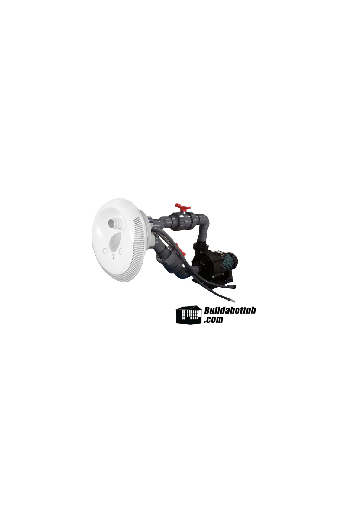
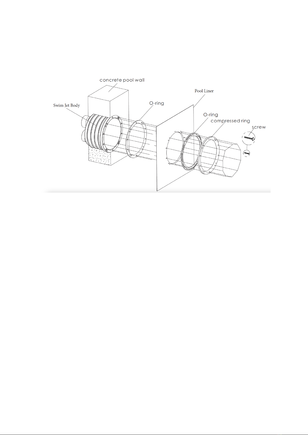
The physical body of the jet is 260mm in diameter or 10.24”, if you are looking to
leave a hole you should leave 11” diameter so there is adequate space for a concrete
fill and seal around the jet body.
Once the pool or tub surface has been finished with tiles, pool paint or the like, the
next step is to assemble the faceplate.
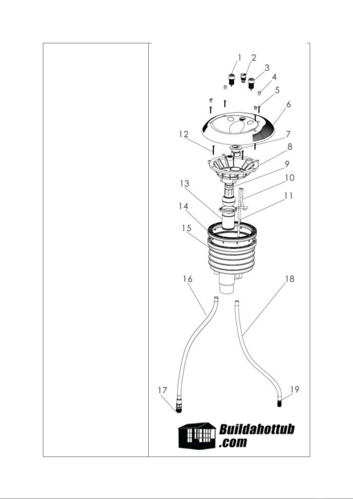
Firstly, the Air Tubes (for the press buttons part #10) should be attached to the
button for the light (part #3) as well as the button for the pump (part #1). Please note,
you will need to remove the screw nut on the top of them in order to attach the tub.
Before you attach the tub, place the screw nut onto the air tube so it can be
tightened in place afterwards.
With the air tube secured on each of the buttons, slide the protective pipe covers
(part #11) down the air tube to the of the tube where it meets the button. This pipe
cover protects the air lines.
Next, thread the power cord for the LED Light, as well as the two air button tubes out
the back of the base of the swim jet and into the conduit (part #16). You can then
attach part #16 onto the base (part#15) and tighten part #17 the cable gland.
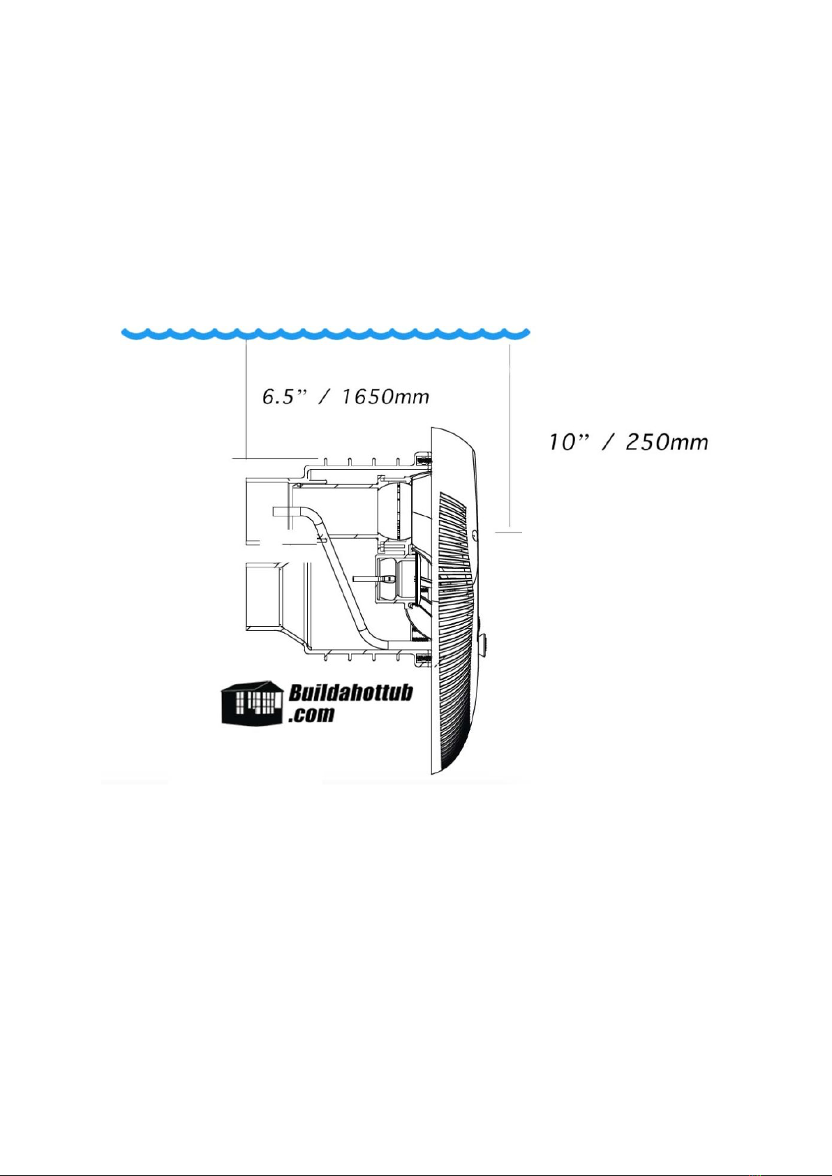
Please note, the final position for parts #16 and #18, should be above the water line
as shown in the final installation diagram below.
Next, part #8, the support frame should be slid into place firmly in the base (part #15)
and then screwed into place using the M6 screws (part #12)
Finally, the face place (part #6) should be placed over the supporting frame (part#8)
and screwed into place using the M5 screws x 4 (part#5)
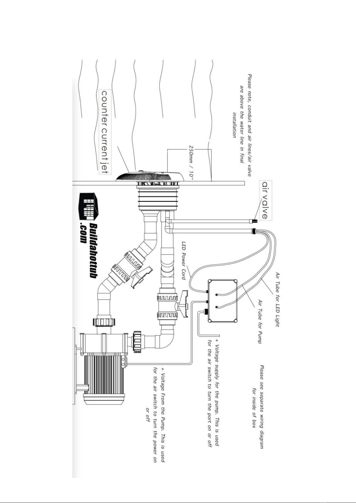
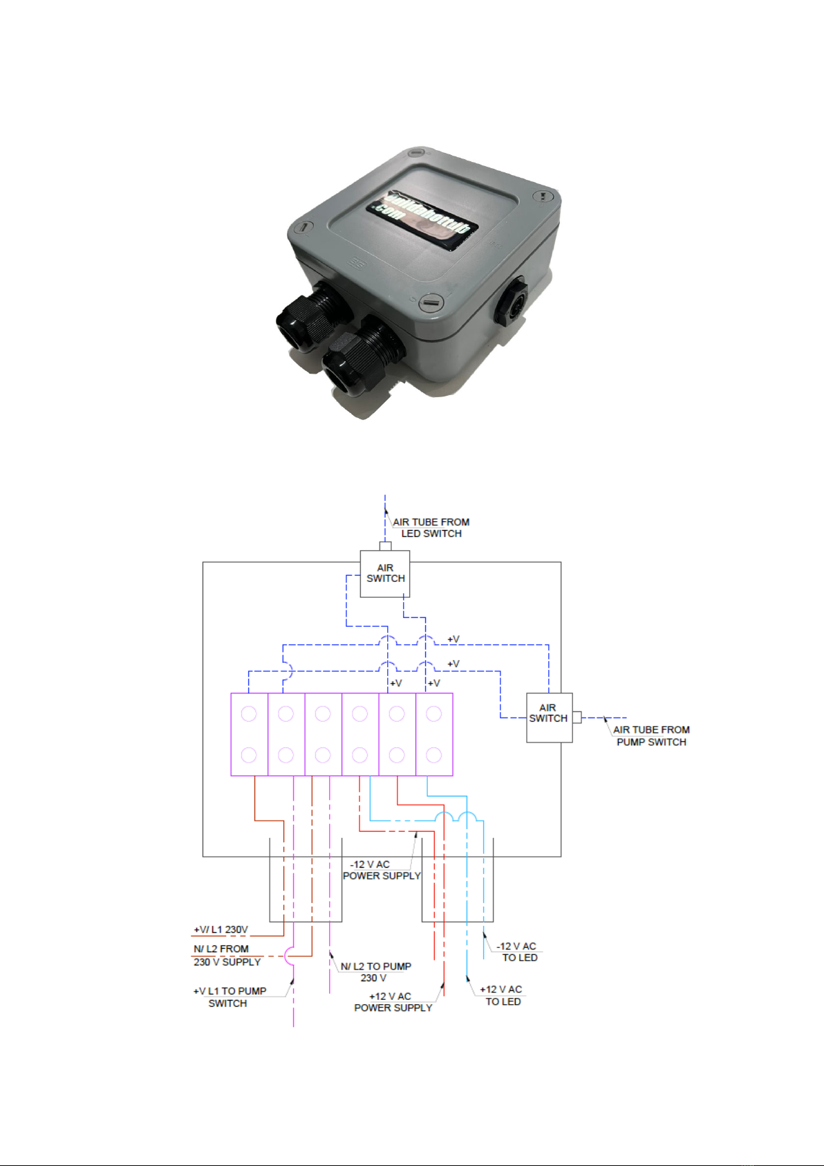
Please see the separate section on how to wire the Swim jet.