9
IGNITION WIGNITION WIRIRE(S) (WHITE) and (WHITE WITH RED STRIPE) (+12V in run, crankE(S) (WHITE) and (WHITE WITH RED STRIPE) (+12V in run, crank
and s metimes access ry)and s metimes access ry)
Make all c nnecti ns as cl se t the igniti n switch as p ssibleMake all c nnecti ns as cl se t the igniti n switch as p ssible..
The igniti n wire(s) are als l cated in the main harness c ming fr m the igniti n
switch. Check y ur chart f r pr bable c l rs and pr be each wire with y ur pr vided
test pr be. The c rrect igniti n wire(s) will sh w +12V and the RED light will gl w
bright when the igniti n switch is in the RUN, CR
RUN, CRANK ANK and s metimes in the
ACCESSOR
ACCESSORYY (newer GMs) p siti n. The c rrect wires will n t sh w +12V when
in the OF
OFFF r AACCESSORCCESSORYY p siti n ( ther than s me GMs).
1. If your vehicle has only one (1) ignition wire connect the heavy gauge
WHITE
WHITE wire to the Ignition #1 wire in the Ignition Switch Harness.
2. If your vehicle has (2) ignition wires, connect the WHITE
WHITE wire as stated
in step 1, to Ignition #1, then connect the heavy gauge WHITE WITHWHITE WITH
RE STRIPERE STRIPE wire to the Ignition #2 wire in the Ignition Switch Harness.
3. If your vehicle has (3) Ignition wires connect the heavy gauge WHITE
WHITE
wire to the Ignition #1 wire and Ignition #3 wire in the Ignition Switch
Harness. Make sure you connect the WHITE WITH RED STRIPE wire to
the Ignition #2 wire as stated in Step 2.
ACCESSORACCESSORYY WIRE(S) WIRE(S) THATHATT POWER POWER THE HEATHE HEATER/BLOWER MOTTER/BLOWER MOTOR (WHITE WITHOR (WHITE WITH
BLACK STRIPE) (+12V in run r n p siti ns). BLACK STRIPE) (+12V in run r n p siti ns). This wire is als in the main igniti n switchThis wire is als in the main igniti n switch
harnessharness. Make this c nnecti n as cl se t the igniti n switch as p ssib. Make this c nnecti n as cl se t the igniti n switch as p ssible.le.
M st vehicles will have ne (1) access ry wire; h wever s mes me F rds, newer GM vehicles
and Chrysler 94 and up will have tw (2) r m re access ry wires. Check y ur wire c l r
chart and then verify these wire(s).
The c rrect wire(s) will sh w +12V and the RED
light will gl w bright
when the igniti n switch is in the ACCACC r RUN RUN r p siti ns, but never
OFF
OFF r CRANKCRANK.
1. If y ur vehicle has nly ne (1) access ry wire c nnect the heavy gauge WHITE WITH
WHITE WITH
BLACK STRIPEBLACK STRIPE wire t this wire.
2. If y ur vehicle has tw (2) access ry wires (s me GMs and m st F rds), c nnect the
WHITE WITH BLACK STRIPE
WHITE WITH BLACK STRIPE wire t b th access ry wires. In s me cases, if y u did
n t use the Igniti n #2 heavy gauge WHITE WITH RED STRIPE
WHITE WITH RED STRIPE wire (if y ur vehicle
d es n t have an Igniti n #2 wire) y u can take that WHITE WITH RED STRIPE
WHITE WITH RED STRIPE
wire and attach it t the Access ry #2 wire, this way y u d n t have t tie b th the
Access ry #1 wire and the Access ry #2 wires t gether n the WHITE WITH BLACK
WHITE WITH BLACK
STRIPESTRIPE wire fr m the main m dule.
ST
STARARTTER/CRANK WER/CRANK WIRIRE (YELLOW WITH BLACK STRIPE) (+12V in the stE (YELLOW WITH BLACK STRIPE) (+12V in the start p siti n nly)art p siti n nly)
Make all c nnecti ns as cl se t the igniti n switch as p ssibleMake all c nnecti ns as cl se t the igniti n switch as p ssible..
The starter/crank wire is als in the main harness. Check y ur chart f r pr bable c l rs and
verify the wire
. The c rrect wire(s) will sh w +12V and the RED light will gl w bright
nlynly in the crankcrank p siti n. This wire will n t sh w +12V in any ther p siti n. Attach the
YELLOW WITH BLACK STRIPE
YELLOW WITH BLACK STRIPE wire t it. NOTE: S me vehicles use tw (2) starter/crank
wires (m stly Nissans and Audis). In this case, c nnect b th wires fr m the igniti n switch
harness t the YELLOW WITH BLACK STRIPE
YELLOW WITH BLACK STRIPE wires fr m the main m dule.
LOCATING & MAKING CONNECTIONS
N te: Rem ve any paint bel w the
spade c nnect r.
Fact ry B lt
Spade C nnect r
Black Gr und Wire
CHASSIS GROUND (BLACK)CHASSIS GROUND (BLACK)
L cate an easy t get t b lt r screw l cated under the drivers side f the dash
and attach the BLACK
BLACK gr und wire fr m the 9-pin harness securely as pictured.
UTILISATION DE LÉMETTEUR DE TÉLÉCOMMANDE
PROGRAMMATION PAR LUTILISATEUR
ÉMETTEURS DE TÉLÉCOMMANDE SUPPLÉMENTAIRES, AVEC TÉLÉCOMMANDE
EN ÉTAT DE MARCHE
Appuyez sur la pédale de frein et maintenez-la. Ensuite, pressez et maintenez le b ut n
n
1 de la téléc mmande en état de marche pendant envir n cinq sec ndes u jusquà
ce que les feux de stati nnement clign tent une f is. Relâchez le b ut n n
1 de cette
téléc mmande et appuyez sur un b ut n quelc nque de la n uvelle téléc mmande.
Les feux de stati nnement clign tent tr is f is; la n uvelle téléc mmande est maintenant
pr grammée.
ÉMETTEURS DE TÉLÉCOMMANDE SUPPLÉMENTAIRES, SANS TÉLÉCOMMANDE
EN ÉTAT DE MARCHE
Suivez dab rd la méth de deffacement de la mém ire de la page 36 puis appliquez
la méth de dinitialisati n de la page 33.
Option av c/sans tachymètr
Appuyez sur la pédale de frein et maintenez-la. Ensuite, pressez et maintenez le b ut n
n
2 de faç n que les feux de stati nnement clign tent deux f is; relâchez ce b ut n
puis pressez et relâchez le b ut n n
1; les feux de stati nnement clign tent une f is.
Le système est maintenant pr grammé en m de de tachymètre. Si v us pressez et
relâchez de n uveau le b ut n n
1 et si les feux de stati nnement clign tent deux f is,
le système est pr grammé en m de sans tachymètre. Relâchez la pédale de frein; les
feux de stati nnement clign tent tr is f is.
R marqu : Le réglage par défaut de lusine est le m de sans tachymètre.
Programmation d la mémorisation du tachymètr
Appuyez sur la pédale de frein et maintenez-la. Pressez et maintenez le b ut n n
2
de faç n que les feux de stati nnement clign tent deux f is. Relâchez le b ut n n
2
puis pressez et relâchez les b ut ns n
s
1 et 2 en même temps; les feux de stati nnement
clign tent deux f is. T ut en maintenant la pédale de frein, démarrez le véhicule à laide
de la clé de c ntact. Quand le m teur t urne, pressez les b ut ns n
s
1 et 2; les feux
de stati nnement clign tent une f is p ur indiquer que le m de de mém risati n du
tachymètre est entré. Relâchez les b ut ns n
s
1 et 2; envir n cinq sec ndes plus tard,
les feux de stati nnement clign tent tr is f is. Le signal de tachymètre est maintenant
mém risé. C upez le c ntact et relâchez la pédale de frein.
Démarrag (1 Démarr l mot ur.)
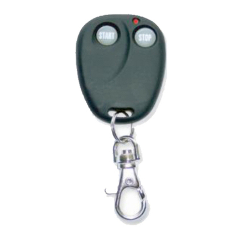
Pressez et relâchez le b ut n n
1.
Le m teur démarre à distance.
Arrêt (2 Arrêt l mot ur.)
Pressez et relâchez le b ut n n
2. Le m teur sarrête.
Arrêt av c mot ur n march : Pour sortir du
véhicul n laissant l mot ur n march
Assurez-v us que le levier de vitesses est à p siti n de
stati nnement (P) et nappuyez pas sur la pédale de frein.
Pressez et relâchez le b ut n n
1 (démarrage) avant de
mettre la clé de c ntact à « OFF ». (Le m teur c ntinue de
t urner pendant 15 minutes u jusquà ce qu n appuie sur la pédale de frein).
Démarrag
Av c la télécommand d c néc ssair : Pressez et relâchez le b ut n n
1.
Av c la télécommand du télédév rrouillag usin : Pressez tr is f is le b ut n
de verr uillage. Av c un alarm d d uxièm mont : Pressez le b ut n de deuxième
canal de lémetteur de téléc mmande.
Arrêt
À laid d la télécommand d c néc ssair : Pressez le b ut n n
2.
À laid d la télécommand du télédév rrouillag usin : Pressez de n uveau
tr is f is le b ut n de verr uillage. À laid dun alarm d d uxièm mont :
Pressez et relâchez le b ut n de deuxième canal de lémetteur de téléc mmande.
36

