Buller Enterprises Panel Pro 6126 Instruction Manual

1
Panel Pro
MODEL 6126
SN 3001 and subsequent
OPERATION AND MAINTENANCE INSTRUCTIONS
copyright 2021
Buller Enterprises, Inc.

2
Table of Contents
Page
Description of Panel Pro 6126 3
Set Up Panel Pro - Hardware Setup 5
Software Setup 12
Try it out 14
Manual movement with keys and mouse 17
Cutting Files 18
QCAD 23
Troubleshooting 33
Maintenance 36
3 axis operations 39
Accessories 42

3
DESCRIPTION OF THE PANEL PRO 6126
The purpose of the Panel Pro is to route complex assemblies of lines, points, circles,
and arcs in sheet aluminum. It accomplishes this by reading a dxf file generated by
popular computer aided drafting programs. This is especially useful since commonly
used shapes such as instrument cutouts can be drawn and stored for subsequent
combination into various instrument panels. The machine is also useful to fabricate
various adapters and brackets that have many corners and cutouts.
Panel Pro 6126 system is comprised of the Controller, the software, and the machine.
The SC3 Controller is the interface between the computer and the machine. It
controls:
x, y, and Z stepper motor drive
Switched GFCI protected ac power for the coolant pump and spindle motor.

4
AvCAM is the operating software. The software is the key to the entire system. It
generates all of the control signals to control the Panel Pro. Also included with the
system is QCAD and the Drawing library which is an extensive library of instrument
panels and instrument cutouts
The Panel Pro shipping crate contains the following items:
1. The Panel Pro base, x,y, and z axis assemblies
2. 4 legs to be attached by user
3. 3 stepper motors and motor to lead screw couplers for X and Y axis.
4. 1 stepper motor with knob and coupler for Z axis.
5. Bosch Router with ER11 adapter installed.
6. SC3 controller
7. 5 gallon coolant tank (drain & filter housing in tank for shipping)
8. Submersible coolant pump
9. AC power cord, X axis & YZ axis controller cables, and USB cable
10. Tool kit with various tools, starter supply of end mills, etc.
11. Software: AvCAM & QCAD, and Drawing Library (inside the 3 ring binder)
12. Optional Measure Pro.
13. Optional EG2 engraver.
14. Optional Diamond engraver.
15. Optional King air panel spacer kit.
16. Optional LZ2 laser engraver.
This manual is intended to help with set up and get you started with operation.
Detailed function and operating information can be found in the AvCAM help file.
Training
While most of our users are able to learn Panel Pro operation by careful study of the
paper manual and help file, training is available either at your location or ours. For new
machine owners, we can train at your continental U.S. facility for direct expenses
incurred. You are welcome to travel to our facility for no charge training. Call us if you
would like to schedule training 701-255-7640.

5
SETTING UP THE PANEL PRO
Planning the area:
You should have enough room for access on the front side (the deep side of the drain
pan), left and rear sides. The computer should be on a table that is located at a
right angle so that the right hand can reach the keypad, and the left hand can
reach the router.
Electrical Service:
The Panel Pro should be on its own 20 amp 120vac circuit. If there are any other loads
on the circuit, they must be light loads and not heavy loads like an air compressor, air
conditioner or other motor. Do not use extension cords.
The circuit absolutely MUST have a proper ground! The computer running the panel
Pro may be on the same circuit. It is just essential that there is the same ground on
both the Panel Pro and the computer.
The Bosch router draws around 12 amps at turn on. If extension cords are used or
other loads on the circuit cause the voltage to dip, it may cause the processor in the
controller to lock up or work erratically.
Nearby running water is highly recommended to wash chips off of hands and finished
parts, and to replenish the coolant. A laundry tub works great for this purpose.
Hardware setup:
1. After removing the crate top, remove the 2x2s in the top ends of the crate.
2. Remove the screws in the shipping tabs at the ends of the Panel Pro. A long
extension with a 5/16 socket is helpful here.
3. When unpacking or lifting the Panel Pro, take care to lift only on the square structure
on the ends, or the material mount bars mounted near the ends. Never lift or put
pressure on the lead screws or the lead screw guards.

6
4. Attach leg glides (inside tool box) to legs. Set near maximum extension.
5. Remove the shipping tabs, keep the screws and place one of the washers under
each 6mm x 16 socket head screw
6. Have all of the 6mm leg mounting screws barely started with one washer on each. If
there is no washer, the screws will bottom out and not secure the leg.
7. Attach the legs with 4 6mm socket screws and washers
each, using a 5mm Allen wrench with an extension.
A 5mm Allen bit is included in the tool box.
Two people are required.
Stand the base unit on the end of the drain pan and have
one person support it in that position while the other
attaches the legs. DO NOT APPLY PRESSURE TO THE
LEAD SCREW, LEAD SCREW SUPPORTS or LEAD
SCREW GUARDS!
8. Level the machine by placing your most accurate level
on the X1 bearing rail (the aluminum extrusion deep
end of the pan). Adjust the leg glides for an exact left to
right level. Repeat on the X2 bearing rail extrusion. Note that common levels are
not sensitive enough. When leveling is as close as you can get it, adjust the leg
glides on the left end so that both x1 and x2 lead screws touch their stops
simultaneously.
9. Run the x axis to about 6” from the right side stops before installing the x axis motors
by turning both lead screw knobs located on the left end.

7
Note for all motors. Install and tighten the 4 mounting screws, then tighten the
coupler.
10.Install the “X1” motor (the motor nearest
to the deep side of the drain pan) with the
leads facing down, using 4 5mm screws
located in the box with the motors. Rotate
the coupler already installed on the motor
shaft for access to the clamp screw
before installation. The 5mm screws
are fastened with a 4mm wrench found in
the tool box. Tighten coupler to lead
screw with the 3mm Allen wrench.
Access to the coupler clamp screw is
through a hole in the lead screw guard. Make sure there is no slippage between
the coupler and lead screw.
11.Install the X2 motor similar to step 10. Install the 4 motor attach screws and then
tighten the coupler clamp.
12.
After both X1 and X2 motors are
installed and the couplers tight, move
to the left side of the machine and
grasp the 2 knobs. Turn counter
clockwise until the X1 and X2 lead
screws reach a hard stop. The stop is
a set screw that extends through the
motor mounting plate. The stop
screws are set at manufacture and
should not be changed. This is the
point that the X and Y axis are square.
If the machine is not properly leveled in
step 8, you will find that when the first
end reaches its stop, the other will feel
like it is acting against a spring till you reach the stop. Re-level.
13. Install the “Y” motor in a similar fashion with the leads facing down. Attach the Y
motor to the connector closest to the motor. Tighten coupler to lead screw. Make
sure it does not slip.
14. The Z axis is shipped in the “down”
position. It will be necessary to lift it up to

8
gain access to the coupler clamp screw as shown. It will be quite stiff. That is
normal.
15.Install the Z axis motor with the 4 screws. Then tighten the coupler clamp screw.
Make sure it is tight and does not slip.
16.The coolant system is used on the Panel Pro consists of:
1. Submersible pump
2. hose support
3. Modified 5 gallon pail
4. 7 ft 3/8 ID tubing
5. ¼ female npt thread to 3/8 ID hose
adapter
6. screen
7. 1 gal Koolmist
8. Drain fitting in Panel Pro pan.
Attach 90 degree
elbow (part of pump)
and the hose adapter
found in the same
package as the hose
with the hose pointing
up.
Place the pump in the
pail with pump inlet
on the bottom. Place
the pump and tank on the floor with the large hole
positioned under drain hole in the pan.
Place screen on pail, position under the drain with
tubing and cord facing the upper right corner of the
Panel Pro.
Connect the 3/8 ID tubing from the coolant pump to the elbow near Y axis stepper motor
Connect the coolant pump power cord to the GFI connector on the back of the
controller.
Add about 3 gallons of coolant. The instructions on the Koolmist bottle indicate adding
4oz of Koolmist per gallon of tapwater. We recommend about 6 oz Koolmist per gallon.

9
Take note of the resulting color. Future coolant additions can be made by
approximating the color of the mix rather than exact measurement. When properly
mixed the color will be similar to Windex and have a distinct oily feel.
Check the coolant level before use by simply removing the lid and observing the level.
If it is less than about 2/3 full, add a gallon.
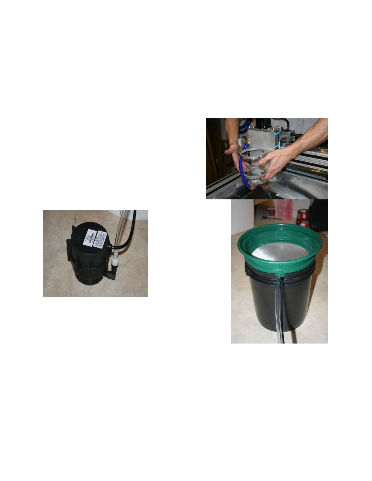
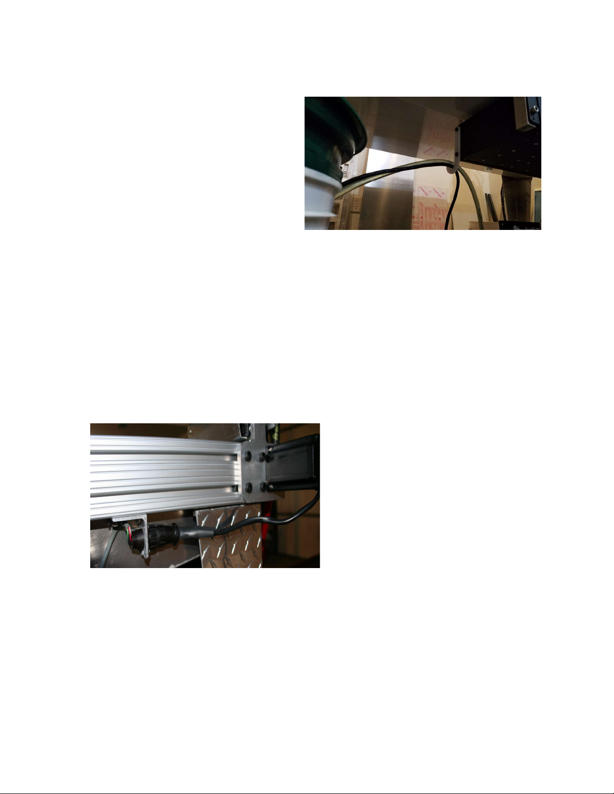
During use, if the coolant looks milky in the hose leading up to coolant spout, then the
pump is sucking air. Take care not too add too much coolant during cutting to prevent
overflow when all of the coolant drains into the pail.
The coolant level in the pail should cover the motor at all times for proper motor cooling.
You will find that you will need to add water frequently. It may not be necessary to add
Koolmist every time, but if the color becomes less blue, then the mixture is too lean, and
it loses lubrication capability.
The cutting process will create a sludge of very fine metal particles. Plan to replace the
coolant and clean the pail every 3-4 months or sooner.
Plan to clean the chips out of the drain pan every day. The chips may be scraped uphill
in the drain pan to facilitate draining.
.
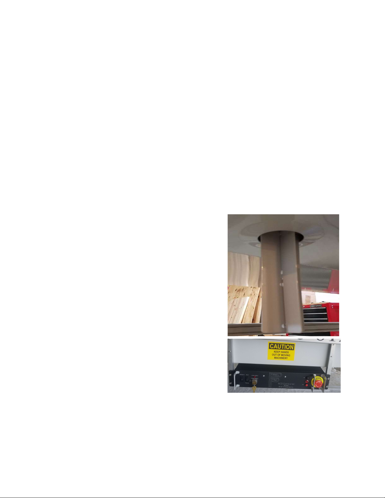
17.You will find the 2 pieces of the flow director as flat pieces of aluminum shipped
inside the coolant pail. Fit the 2 pieces together and Install it in the drain hole. Its
purpose is to prevent coolant splashing beside the screen in the pail when a large
volume of coolant is poured in the pan. It is shown assembled and installed to the
right.
18.The controller mount bars (shipped in the tool box) are mounted to the front of the
drain pan. Supplied with the controller mount bars are 8 each 6x25 mm socket head
screws. Liberally apply silicone seal under the head of 4 of the 6mm socket head
screws. Loosely install the controller mount arms
to the drain pan with these screws. Attach the SC3
controller to the arms with the remaining 4
6x25mm screws. Line up the arms and tighten the
screws. There is a bag packaged with the
controller that includes the laser key and a 2 pin
shorting plug. The 2 pin shorting plug
MUST be installed on the rear of the controller in order for the
controller to turn on. The plug is provisions for a customer supplied safety
curtain.

1
0
19. Remove the bottom #10 screw from the
left, aft corner of the controller that
faces the coolant pail. Loosen the top
screw that holds the J shaped hose
support. Swing the support down and
reinsert the bottom screw.
Place the coolant hose and power
cable on this support to maintain an
angle that keeps coolant from following
the hose to the floor.
20. Verify AC power off! Attach the X interconnect cable 16 pin Amp connector to the
controller. The controller connector has a keying pin to prevent installation on the Y/
Z connector. The X axis cable will have 2 connectors with angle brackets.
The X1 axis has a 3 pin white connector for the X axis limit switch and a 2 pin
connector for a laser warning light.
21. Locate the nuts with screws installed on the bottom of the right rail. Allow enough
room to comfortably attach the motor plug. X2 axis is shown. Note that the tie wrap
nib on the connector mount fits in the bottom channel with the plug parallel to the
extrusion.
22. Verify AC Power off! Attach the Y/Z cable and route cable. The Y/Z cable is the
same on both ends and it does not matter which end goes on the controller or the Y
axis. The spindle (router) power cord should run parallel with the Y/Z cord.
If you have the urge to tie up cables take precaution to leave plenty of room
for the cables to move full travel left to right and provide plenty of room to
flex. Leave a dip in the cable to provide a place for liquid to drip off before

1
1
getting to the controller. The cables are generally not visible from normal
viewing angles and do not require additional wire ties etc.
23.Route the pump power cord to the SC3 controller and connect to the GFCI AC
receptacle on the SC3 controller.
24.The Bosch collet system supports a ½ or ¼ “ router bit shank. Since it is desirable
to accommodate many different sizes of tool diameters, we have installed an
adapter to use an industry standard ER11 collet available in many sizes up to ¼
inch. Place the collet into the nut without the end mill in place so the collet can
compress and snap around the quarter moon shaped extractor ring in the collet nut.
When properly installed, the collet should be nearly
flush with the nose of the nut. If installed incorrectly, it
will cause cutting problems. The picture below shows
the collet when properly installed.
25. Loosen the 2 router mount clamps on Z axis and
install the Bosch router so that the top clamp is resting
on the bottom side of the top router housing. Snug the
clamp screws equally. Don’t over tighten.
26. The bottom 43mm clamp (accessory mount) is used for the engraver and other
accessories. The lower clamp tightening screw may be removed for normal use.
Don’t clamp it down tight without an engraver or touch probe installed or it may bend
it making it difficult to install the engraver or other accessories.
27. Insert a 3/16 collet with a 1/8” end mill (double ended with 3/16 shank) with about ½
to 5/8” protruding from the collet nut. Use the supplied 16mm wrench on the shaft of
the Bosch router. Use a 17mm wrench on the ER11 collet nut. This adapter uses
industry standard ER11 collets. We stock 1/8, 3/16, and ¼ inch ER 11 collets.
When installed correctly, the collet should be almost flush with the end of the collet
nut. With the collet nut removed, look in the back at the threaded end of the collet
nut. Note there is an off center ring near the bottom next to the tapered surface.
This is the extraction ring. To install the collet, angle it into the back of the nut so the
groove in the collet engages that extraction ring. After the collet is installed, the end
mill can be inserted.
28.Plug the router cord into the connector on the Z axis.

1
2
29. Plug the AC cord that exits the machine near the Y axis stepper motor into the GFCI
AC socket on the SC3.
Note: the GFCI test cannot be completed until the computer has commanded the
spindle and pump power on, and the manual switch on the controller is on. It should
be tested weekly.
30. Install the usb driver (CDM21228.exe on the flash drive) before plugging the
usb cable into your computer! See the following section on software
installation. The usb driver does not need to be installed if the computer will not be
used to run the Panel Pro (offline use).
31.Connect the AC Power supply cord to the SC3 socket. Connect the other end into a
grounded 20 amp 110VAC circuit not shared by other equipment.
Recommended computer:
Windows XP or Vista are not supported and AvCAM will not install.
QCAD needs a 64 bit processor.
We recommend using a desktop style computer running Windows 10 operating system.
We also recommend 8GB memory. If a computer is used that has been used for other
purposes, clear out any unused programs. The only programs you should have open is
AvCAM and QCAD(or other cad program). The keyboard that will control the Panel Pro
absolutely must have a numeric key pad and the mouse must have a mouse wheel.
While a lap-top will run the Panel Pro, the numeric key pad is used frequently. An external
key pad may be employed, however the Num Lock has to be on to use it, and then it
remaps the main key board so that the U,I,O,J,K,L,M keys are now number keys. If you
have to type in a file name, it becomes awkward switching the num lock on and off.
Also plan to have at least a 17” monitor with about 1024 x 768 pixel setting at least for
drawing.
Arrange the computer so that the right hand can be on the keyboard or mouse and
the left hand can reach the middle of the Panel Pro. Do not extend the supplied 10
foot USB cable.
Software Installation:
Install the usb driver software (CDM21228.exe) before
plugging the usb cable to the controller!
You must have administrative privileges AND run as administrator.

1
3
The software will install on Windows 10 64 bit computers.
The USB driver, AvCAM, QCAD and the drawing library are located on your AvCAM
USB drive.
Navigate to the usb drive, right click QCAD autorun.bat and then Click run as
administrator.
The CDM21228.exe file installs the usb drivers appropriate to your operating system
including 32 and 64 bit win 7 and win 10 operating systems.
I
The USB drivers load first, then AvCAM, then the drawing libraries.
If you are asked to reboot the computer, say no and wait till the command prompt goes
away. You will be asked to hit any key in between each install segment above.
QCAD will need to be installed manually by double clicking QCAD……..MSI
AvCAM: load the AvCAM thumb drive into your computer. If the AvCAM install does
not start automatically, go to Windows Start\run\E:QCAD autorun.bat where E is your
usb drive number. This batch file installs AvCAM sets up the proper folders and copies
the drawing libraries.
Note the application key on the thumb drive envelope is your machine serial number.
It will be required on the first time the AvCAM program is run on each computer it is
installed on. The Activation key is the number only, no text i.e. 2110.
Important! A valid email address is required to provide you with AvCAM updates.
Send that email to [email protected] and identify your self as the Panel Pro contact.
Install QCAD: To manually install QCAD:
double click qcad-3.xx.x-pro-win64-installer.msi (or later version)
We purchase a QCAD pro license for you. Whoever was the email contact when the
machine was purchased will receive an email with download instructions. This link is
active for one year, however the usb drive has the version current at time of shipping.
For additional QCAD licenses or to renew downloads after one year, contact QCAD.org.

1
4
We supply a papeback QCAD manual with the machine.
See QCAD quick config
.pdf for qcad set up suggestions.
Drawing Library: the drawing libraries should also install automatically. To manually
install: set up or navigate to C:\drawings
Use windows explorer (Windows +E), copy the aircraft and instrument folders into the
Important. You should set your screen saver / power modes so that the screen saver
will not activate while the Panel Pro is running. We suggest a minimum of 2 hours so
that the USB communications do not get interrupted. If USB gets interupted, then
communications will need to be re-established (F2) and the machine will have to be re-
homed.
Try it out:
Power up sequence. Boot up the computer, turn Panel Pro controller on, open AvCAM.
Controller power up: If your controller has an emergency shut off switch, release the
shut off by turning the knob clockwise until it pops out. Press the “on” push button
switch, the red light lights up. To turn it off, push the “off” button below the pilot light.
Pressing the emergency shut off or the red momentary switch will depower all drive and
spindle operation. The interlock jumper plug must be installed or the controller will not
turn on.
Turning power back on after emergency or normal shut off will not cause any movement
or spindle power turn on.
Normal turn off: Close AvCAM, then turn off the controller.
When AvCAM opens, it looks for the Panel Pro on the USB list. If found, it knows the
serial number of the machine and no further activation is needed. If the Panel Pro USB
is not found, the user is asked for an activation key on first program opening which is
simply the machine serial number. Subsequent program openings with the controller off
will simply open AvCAM in the offline mode.
Assuming the Panel Pro was found the controller is queried and if the controller power
is on then communications is established and the message “firmware version 2.6 found”
(or later version) appears on the status bar on the bottom of the page.
If controller power is off or not connected, the message “controller offline” appears.

1
5
If AvCAM – Machine – Hardware settings shows the Panel Pro sn3xxx but hitting
connect does not initiate communications, turn off the SC3 controller, close AvCAM,
wait about 30 seconds. Turn the controller back on, open AvCAM..
CAUTION!
There should be no reason to be injured while operating the Panel Pro if a few simple
precautions and common sense are exercised.
The SC3 is powered by 110vac and switches 110vac for the coolant pump and router.
Any leaks or spills should be corrected before further machine use.
Operate only on a dry floor.
Test the GFCI outlet with the router running (click spindle on status bar and check
spindle on) before each use. Press the test button on the GFCI, and the router should
stop. Press the reset button on the GFCI with AvCAM commanding spindle on to
resume operation.
Do not operate the machine if the floor in the area is wet.
If any coolant leak is noticed, immediately disconnect the power from the SC3
from a dry location and repair the leak. Make sure any area where power cords
run are dry.
Under no circumstances should the guard around the router bit be removed while the
router is running. Coolant and metal chips will fly everywhere.
Safety glasses are recommended. As the milling bit performs drilling operations,
sometimes some chips can fly.
Ear protection is required. Keep hands clear of pinch points.
We make no claims as to the medical properties of or continued exposure to aluminum.
It is recommended that you avoid contact with the copious chips generated by the
cutting action. The chips are sharp and can easily embed themselves in the skin.
Nitrile gloves are quite effective at keeping chips at bay.
Chips should be flushed off with running water. If flushing with water does not remove
chips, or metal slivers, then rubbing with clean Scotch Brite will often remove small
metal slivers.
Keep fingers away from moving parts to keep them from getting pinched. When the
pressure builds up the stepper motors will start skipping steps, but a painful bruise
possibly a broken bone could result if fingers (or other parts of the body) are placed
between moving and non moving parts.

1
6
Keep fingers away from the router bit. It will cut fast and sure. Again DO NOT
REMOVE THE GUARD! KEEP FINGERS CLEAR!
Turn the SC3 power switch on. Click on the turqouis AvCAM icon on your desktop to
open the AvCAM program. This is the preferred turn on sequence.
If you are connected and the SC3 controller is working the status bar on the main
screen will read “firmware version 2.6 found” (or later version)
If connected to the controller then the status bar will read “controller offline”. In this
case, open the options > hardware menu.
Once communication is established, verify all of the settings. Open the various setting
dialogs and review the settings.
Information on the settings can be found in the help file. Click F1 to get context
sensitive help on any open window. The help file is the main operating manual
for the Panel Pro.
If the help file is not found, navigate to the folder where AvCAM is located if prompted
and locate AC19.chm.
After the machine is set up and communications established then hit the keyboard “J”
or “1” key to enter the jog mode. If the jog buttons are visible on the upper left corner of
the screen, you are already in jog mode.
On successful connection, a message box will ask you if it is ok to move to machine
home. Unless you have a failed home switch, you always want to allow the home
function to run so that the software position is synchronized with the hardware position.
The X, Y and Z axis may be exercised from the jog menu. Note that until Z Zero is set,
all axis will move at slow speed. To temporarily move at high speed, hit the 7 key.
The jog functions may be exercised using a mouse on the buttons on the upper left side
of the screen, or equivalent key pad keys.
Look in the help file contents for shortcut keys.

1
7
The keys referred to below are the numeric keypad keys, not the number keys at
the top of the keyboard.
To move the x axis left, push and hold the 4 key on your numeric keypad. Assuming
that the machine has been properly homed on power up, the software will limit travel to
the extents of the machine. As a result, the x axis moving left as above will stop at the
farthest left extension just short of the hard stop. If any axis hits a hard stop, it will
normally not hurt anything, but position synchronization will be lost. That axis (or all
axis should be re-homed).
The x axis, set in motion above may be stopped by releasing the 4 key
The 6 key will move the x axis right.
The 8 key moves the Y axis away from the operator, the 2 key moves it towards the
operator. Note that until the Z zero has been set, all movement will be at a slow speed.
There are jog buttons on the screen as well. Click and hold to move. Keep the pointer
on the button and release to stop
Z axis:
The home position of the Z axis is all the way up, just short of a hard stop and has a
maximum travel down of about 3.125 inches.
When at any position, hold the 3 key to move move it down at a slow rate until it
reaches the soft limit.
The 9 key raises it all the way to the top, normally at the position where the home
routine found the home switch. This does perform the homing procedure.
The 7 key raises the z axis to retract level.
The 1 key commands z to the cutting depth. (you will need to confirm with enter).
The 0 key will lower z to the z zero level.
There are 3 related z axis positions set on the Z control dialog opened by clicking the Z
axis position on the status bar or tapping the z key on the keyboard.
The Z zero is the point where the end mill or other tool is in contact with the surface of
the material to cut. To set Z zero, hold the 3 key, then release it about .1” above the
surface. Set the axis select under the main screen jog keys to z, and the increment
to .001. Move the z axis using the mouse wheel until a piece of paper gets tight
between the end mill and material. Tap the z keyboard key to open the z dialog. Tap Z
again to set this position as Z zero.
Z retract is the position above z work zero that the z axis will raise to when commanded
up by software. The goal is to use as little time traveling up and down without working

1
8
as possible, but still have the end mill clear clamps or other obstructions. Initially set
this at about 1”. This can be set on the move options page or the z control dialog.
Cut depth is the distance below z zero that the end mill will descend to when cutting, or
actually doing the work that a particular mode is used for. For instance cutting a panel
with a 3/16 shank end mill with 1/8” flute diameter, and ¼” length of cut. (our standard
double ended mill) Assume a material thickness of .090”, and z zero set at the material
surface. Cutting depth should be about -.125. Once Z Zero has been set, the X and Y
axis will jog at the rapid speed if the Z is above zero. See the help file for a detailed
discussion of the Z axis. With any dialog open, tap the F1 key for help relative to that
dialog.
To use the screen based jog buttons, left click on the desired button and hold the
mouse pointer on the button. To stop, release the mouse left click while the pointer
remains on the button.
Note that the AvCAM help file is a dynamic document that is updated
with AvCAM updates. Hit F1 on any dialog for help with that dialog.
Cutting a drawing:
We’ll start our discussion by routing a single instrument hole. For instance, an altimeter
drawing is an individual shape, its reference (drawing origin), was placed at the center
of the instrument. Altimeter.DXF can be found in the Instrument > Standard folder of
the drawing library. When the routing starts, the end mill must be at work zero or other
known location.
For instance, the 0,0 position of the altimeter.dxf file is in the center of the instrument.
Since we want to just cut that instrument, the 0,0 position of the machine must be at the
center of where you want the instrument cut out. The R key may be used to set the
work zero at the current location.
Cut a file from metal larger than the finished part:
The material should be no taller than 27” to allow access to clamp it to the mounting
bars. The nominal x travel is 61” in x direction and 26” in Y. The maximum x travel is
62” but the left side will be off the left side of the bed. The maximum Y travel is 26.25”
Maximum material size is 62” - end mill diameter in x, 26” - end mill diameter in Y.
Material support MUST allow the cutout slugs to drop free so they don’t jam or get
flipped up on to uncut material which would be a hazard.

1
9
Select material of adequate size so the router clears the clamps, which are best placed
in the corners and where the material crosses a mount bar. Generally leave about 1
inch around each edge.
Material should be supported about every foot, and spaced away from the rails so you
don’t cut through the rails. .032 Material should be supported about every 6 inches.
Material spacers are supplied in the tool box. These can be fabricated from inexpensive
paint sticks.
Take care to set the mounting bars and spacers so as NOT to restrict cutout pieces
from falling free
Cut a file from an existing blank:
Use a large carpenter square to square the blank with the x axis bearing rail. Take
care that clamps are placed in areas that will not be cut. Clearance must be maintained
from the end mill, and the collet nut.
End mill:
Use the 1/8” end mill with a 3/16” shank and a .250 length of cut for the normal cuts
on .062 and thicker material. If you need to make 3/32 holes for nut plates, put those
holes on a separate layer and cut those holes first, then change to the 1/8” end mill and
cut the rest of the cutouts. 3/32 end mills can be used on material less than .062 thick.
Use a 1 or 2 flute end mill on 2024T3. Use a 1 flute end mill on any material softer than
2024T3.
End mills may be inspected using a loupe or strong magnifying glass. ANY chipping on
the cutting edge is cause for rejection.
Turn on controller:
The computer and controller may be turned on in any sequence, but normally, turn on
the controller before AvCAM is opened, If AvCAM is started first, then the F2 key must
be hit to establish communications.
Verify that the controller spindle switch is set to auto, and the router on/off switch is on.
Set the work zero using the “R” key or other position setting tools described in the help
file > contents > cutting files.
If Z zero has not been set, set it now.

2
0
Verify coolant:
The coolant performs several functions.
Cools the cutter bit.
Flushes chips off of the material.
Lubricates end mill. Keeps aluminum from building up on the bit. Material buildup
will drastically increase cutting pressure breaking bits.
COOLANT:
The recommended coolant is Cool Mist #78. It does not stain aluminum when rinsed off
promptly after cutting and provides good lubricity. Mix the coolant with 4-6 oz of coolant
to 1 gallon of tap water, note the color of the mixed coolant. As the machine is used,
coolant will evaporate. Often it is only necessary to add water. Watch the color of the
coolant to maintain approximate mixture. It should have a pale blue color. If it is too
weak of a mixture, then corrosion will be more of a problem. Never use only water!
Fill the coolant tank within 5” of the top. If the coolant is too low, it will not pump at
all or there will be bubbles in the clear coolant hose. When bubbles appear dump about
a gallon of water into the drain pan. Clean parts with clear water to remove residual
coolant. Dried coolant leaves a sticky film.
At a minimum coolant needs to cover the pump at all times.
Plan to replace the coolant and clean tank every 3- 6 months, possibly more frequently
in hot locations. If carbon fiber or other composites are cut, plan to change the coolant
after every use.
COOLANT FILTER:
The routing process produces a large quantity of metal chips. Most of the chips will stay
in the pan, The screen on top of the coolant pail will catch what drains through.
Simulate the file before cutting.
The process of simulation does all the work of joining the dxf file entities into the correct
order and direction as well as computing tool paths.
Open the file.
Select the layers to cut.
Select the operating mode (auto tool path for normal cutting)
Open the cut dialog, (blue icon on tool bar with a C in the middle), click nearest cutting
order, Set sim speed at 100 (max) or slower to better visualize the cut. The joining and
Table of contents
Other Buller Enterprises Industrial Equipment manuals