7
Switch 4 - Remote control
If switch 4 is ON (and swit ch 3 OFF), then the decoder has to be
remote cont rolled by the adsbScope software if you use a U SB
interface. The receiver works in USB mode (no data via WiFi). With USB
cable connected to the 4 pin connector (shown on schematics in Chapter
13) the receiver works just as microADSB-USB receiver. In this mode the
firmware of the receiver can be updated.
The switch 1, will have no effect. After power-on or reset, the
decoder will not start to send data by itself; it will wait for a
comman d fro m the soft ware.
If swit ch 4 is OFF, t hen the decoder st arts to send data
immediately after power-on or reset.
Switch 3 - serial
If the s witch 3 is OFF, then the USB-interface will be used. But if
the s witch 3 is ON, t he n t he Wi Fi -Int erfa ce will be us ed inst ea d.
Swit ch 2 - TimeTA G
If this s witch is ON, then a precise time code (for MLAT) will be
generated by the decoder for each received frame. The adsbPIC-
decoder time tag is based on a 12MHz clock. (So me other
decoders/receivers use a 20 MHz clock instead.)
The adsbScope software via U SB can activate the ti me tags by
software. If this was done, then the decoder will send time tags
even if the switch is in open position.The time tag can be used to
triangulate aircraft position in collaboration with other decoders .
If you don’t participate in s uch a net work, then you should
deactivate the time tags to reduce the load at the USB/ W iFi-
Interface.
Switch 1 - DF1 7
This switch has no function, if switch 4 is ON .
If switch 4 is OFF, then this switch controls which frames are
reported to the PC. As long switch 1 is OFF, all received frames
will be report ed to the PC. But if switch 1 is ON, t hen only DF17,
DF18 and DF19 -frames will be transferred.
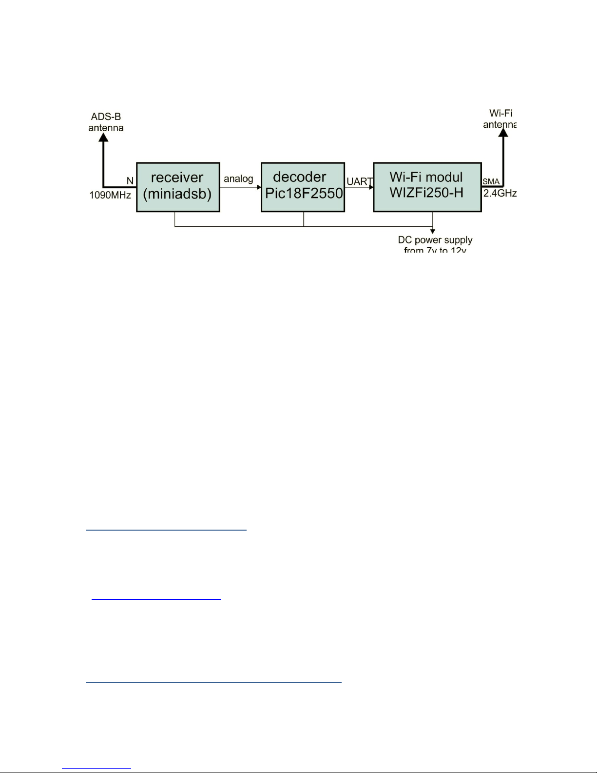
8 TCP/IP and WiFi module
The
rece
i
v
e
d ADS-B
messages
are transferred by serial to the Wi-Fi
TCP/IP converter by module : WiZFi -250-H
For more information, visit website at:
http://www.wiznet.co.kr/Sub_Modules/en/product/Product_Detail.asp?cate1=&
cate2=&cate3=&pid=1201
The integrated in microADSB-WiFi v2 module WiZFi 250 is an
embedded device which provides for ADS-B data transfer based on WI-
FI wireless network standard. It integrates IEEEE802.11b/g/n and
TCP/IP protocol. It can easily make device access to wireless network.