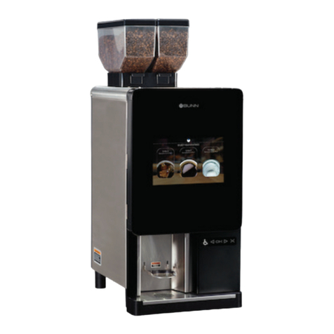
BUNN Espress™ ES•2A™/ES•2SA™
4
HOT WATER RINSE DISPENSING TUBE AND STEAM DISPENSING TUBE
The ES•2A™ ES•2SA™are equipped with a hot water rinse dispensing tube and two steam dispensing
tubes. TheHotWaterrinsedispensingtubeiscontrolledbyaknobcentrallylocatedonthefrontofthebrewer.
TheSteamdispensingtubesarecontrolledbyknobslocatedontheleftandrightsideofthebrewer,rightknob
controls the right side steam tube and the left knob controls the left side steam tube. They can be placed in
acontinuousflowpositionbyturningtheknobsapproximatelyhalfwayaround. Allthreeoutlettubespossess
a rotary ball and socket type fitting for manual positioning.
WATER FEED TAP
This tap is of the automatically closing type. To introduce water into the tank, turn the control to the left
or right, indistinctly and hold it in position. When you release the control, it will automatically close.
LEVEL
Waterlevelshould never rise above themaximumlevelzone(+)and never descend below theminimum
level zone (-), as this may result in the heating element to melt. The optimum water level zone is indicated
with (N). In the models with electronic water level control for the tank, The optimum water level (N) is
maintained automatically.
Tank Thetankismadeofcopperplate,1.5mmthickanditscomponentsaremadeofcastordropforgedbrass.
The tank cover is fixed to the tank by bolts with exterior nuts to facilitate its removal. The operating pressure
ofthetankwheninuseshouldfluctuatebetween0.9and1.2barasindicatedonthetankpressuregaugewith
noair inside the tank. Wheneverthemachine is pressurized, thepressureindicated on the gaugeshouldbe
checked to make sure it is the correct pressure. A pressure drop of 0.1 to 0.2 bar is considered normal. If
there is an abnormal amount of air in the tank, a very quick pressure drop will be observed on the pressure
gauge when one of the steam knobs are turned and steam is released. After a few moments, the real tank
pressure can be read on the gauge.
The difference of 0.9 to 1.2 bar, i.e. 0.3 bar, allows the effective exchange required to maintain the
optimum temperature in the units.
However,itisnecessarythattheinstaller,wheninstallingthemachine,decideattheinstallationsiteitself
through theperformanceofthecorrespondingtests,theadequatethermalpointorcorrectpressure,keeping
inmindtheworkingconditionsofthemachine,thehourlyproductionraterequiredandtheroomtemperature.
PUMP SET
The pump set is made up of a vane type, volumetric pump driven by a 0.25 HP single-phase motor,
supplied at 220 v-60 Hz.
If the water pressure exceeds 7-8 bar, a pressure reducer should be placed between the water line and
the pump set to reduce the output pressure of the water line to between 3-4 bar, which will be the pump set
water feed input pressure.
The output pressure of the pump of the pump set should be between 8-9 bar as a maximum. To check
this pressure, fill the cup of the coffee filter holder with pressed coffee and place it in any one of the infusion
units, press the continuous flow button and read the pressure on the feed line pressure gauge. If the gauge
does not show the previously mentioned values, the pump set’s delivery pressure should be adjusted. This
is done by loosening the screw to reduce pressure. Adjust said screw until the desired pressure is obtained.
The adjustment screw should only be turned very slowly.
NOTE: Pump motor needs to be 1/4 -1/5hp, 1725 rpm, 230 volts, carbonator style, U.L. recognized
FEATURES
