manuals.online logo
Brands
  1. Home
  2. •
  3. Brands
  4. •
  5. Burger & Brown
  6. •
  7. Industrial Equipment
  8. •
  9. Burger & Brown SMARTFLOW FasTie User manual

Burger & Brown SMARTFLOW FasTie User manual

Form #117 (2.09)
4500 E. 142nd Street • Grandview, MO 64030 • Tel. (816) 878-6675 • Fax (816) 878-6683 • www.smartflow-usa.com
General
FASTIE Quick-Connect Knock-Out System “ties-in” the mold ejector plate to the press ejection system. A
pneumatically-operated piston inside the coupler releases the stud from the press ejection system to reduce
set-up and change-out times.
Adjustable or fixed-length FASTIE ejector bars may be used with the couplers and studs. Adjustable ejector
bars allow mold-setters to compensate for variance in molds and presses up to 1/2" in each direction. Fixed-
length ejector bars may be made-to-order for custom installation.
The FASTIE air manifold option distributes shop air to each coupler. The aluminum
manifold supplies air to up to four couplers. Pneumatic fittings and tubing are included.
Caution: Couplers must be in the open position before connecting with
studs. See figure 1. Coupler damage will result from improper set-up.
Do not operate injection molding press with couplers in the open position!
Maintenance
FasTie couplers must be greased to operate smoothly.
Visually inspect coupler each month or each tool change
for the presence of grease. Generously apply grease to
stud end, connect the coupler to the stud, then release
and repeat.
Before Installation
Before clamping a mold to the injection molding machine, machine ejector plate must be completely
retracted to the “home” position.
If using a SpeedBar adjustable knock-out bar, check that at least 1.5" (38mm or 20 complete turns) of the
1/2-13 stud is threaded into the body of the knock-out bar with the dowel pin centered in the adjustment
slot. See figure 2.
SMARTFLOW®
1" FasTie® Quick-Connect Knock-Out System
and SpeedBar® Adjustable Knock-Out Bar
Installation Instructions
figure 2
figure 1
Coupler
Open
Coupler
Closed
SPEEDBAR™
US Patent Numbers:
6,379,072 6,315,544
tel. 816-878-6675 burger & brown engineering
fax 816-878-6683 2
Fixed Bar Installation
The following installation instructions are for reference
only. Installation may vary depending on knock-out
arrangement and pneumatic connection location.
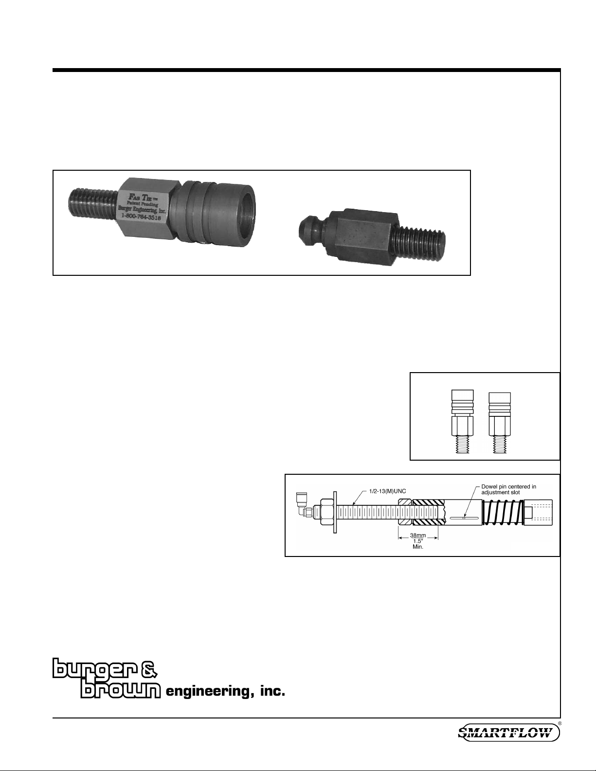
1. Install studs into the mold ejector plate. See figure 3. If
the press has a non-adjustable ejector home position,
insert washers under the stud so the shoulder is flush
with the back face of the mold clamp plate. Use a thread-
locking compound where threaded parts connect to
prevent movement during use.
2. Insert the ejector bar and coupler through the platen and
into the press ejector plate. For presses with non-
adjustable ejector home position, install the coupler (in
the open position) so it extends 1/8"(3.18mm) past the
platen surface. The coupler, in the closed position, will
be flush with the platen surface. See figure 4.
3. Clamp A side mold plate to the machine, making sure the
mold is positioned squarely.
4. Install washer, nut and pneumatic connector per figure 5.
Use a thread-locking compound to prevent movement
during use.
5. If using the manifold accessory, mount the manifold and
tubing so they do not interfere with moving parts.
6. Connect shop air lines to the FASTIE couplers. Couplers
must be in the open position (see figure1) before
connection to male studs, otherwise coupler damage
will occur.
7. Move the platen forward so the coupler and stud are
connected.
8. Clamp the B side of the mold to the platen. Tighten the
nut to the press ejector plate after Fastie components are
coupled. This assures alignment of the FasTie system.
9. Follow “Test Installation” procedure on the next page.
SpeedBar™ Adjustable Knock-Out
Bar Installation
The following installation instructions are for reference
only. Installation may vary depending on knock-out
arrangement and pneumatic connection location.
1. Install studs into the mold ejector plate. See figure 3. Use
athread-locking compound where threaded parts connect
to prevent movement during use.
2. Shorten the SpeedBar to slightly shorter than the
working length to avoid interference during mold setup.
3. Insert the SpeedBar and coupler through the platen and
into the press ejector plate. The coupler must be in the
open position. See figure 1.
4. Clamp A side mold plate to the machine, making sure the
mold is positioned squarely.
5. Install washer, nut and pneumatic connector per figure 5.
Use a thread-locking compound to prevent movement
during use.
6. If using the manifold accessory,mount the manifold and
tubing so they do not interfere with moving parts.
7. Connect shop air lines to the FASTIE couplers. Couplers
must be in the open position (see figure 1) before
connection to male studs, otherwise coupler damage
will occur.
8. Move the platen forward so it just meets the ejector
housing.
9. Clamp the B side of the mold to the platen. With your
hand, push the SpeedBar locking sleeve toward the mold
and turn it clockwise (looking from the nut end) to
lengthen until the female coupler snaps shut, then
release.
10. Tighten the nut to the press ejector plate.
11. Follow “Test Installation” procedure on the next page.
FasTie™ Quick-Connect Knock-Out System and
SpeedBar™ Adjustable Knock-Out Bar
figure 3
figure 4 figure 5
Test Installation
Verify Connection
1. Open the mold.
2. Activate the ejector system.
3. Observe the ejector pins. They should move forward
and return. Visually inspect the FasTie couplers to
verify that they are connected to the studs.
Verify Release
1. Apply air to the FASTIE couplers.
2. Activate the ejector system.
3. Observe the ejector pins. They should move forward,
but not return.
Reconnect Couplers
1. Ensure that the FASTIE couplers are in the open
position. See figure 1.
2. Move the ejector system forward
3. Return the ejector system.
4. Observe the ejector pins. They should be retracted
If the system is not connected properly,open the platen,
disconnect the couplers and studs, and reconnect each
knock-out bar (repeat Steps 7 through the end of
installation, and re-test installation).
tel. 816-878-6675 burger & brown engineering
fax 816-878-6683 3
Limited Warranty
Seller warrants that this product supplied will conform to the description herein stated and that the product will be of
standard quality.This is the sole warranty made by Seller with respect to this product. Seller expressly disclaims any other
express or implied warranties, including, but not limited to, the implied warranty of merchantability and the implied
warranty of fitness for a particular purpose.
Seller shall not be liable for any cost or damages, whether direct, incidental or consequential, including, but not limited to,
any injury, loss or damage resulting from the use of this product, regardless of whether any claim for such cost or damages
is based on warranty, contract, negligence, tort or strict liability. The sole liability of Seller is limited to repairing or
replacing this product.
This warranty shall not apply to any products that have been repaired or altered by anyone other than Seller.The warranty
shall not apply to any products subject to misuse due to common negligence or accident, nor to any products manufactured
by Seller which are not installed or operated in accordance with the printed instructions of Seller or which have been
operated beyond the rated capacity of the goods. Seller states that the product’suseful safe life is 5 years. Actual life may
vary widely depending on operating environment such as temperature, pressure, and chemical exposure.
Troubleshooting
Symptom
Ejector pins don’t move
back when retracting ejector
system
Corrective Action
• Check air pressure
(should be between 80
and 100 psi) testing air
lines for leaks or breaks.
• Check coupler operation.
• Check stud and coupler
alignment.
If corrective action fails to correct the problem,
please contact the factory.
FasTie™ Quick-Connect Knock-Out System and
SpeedBar™ Adjustable Knock-Out Bar
FasTie uncouples during
ejector cycle
• Check mold position in
the machine. Mold must
be squarely installed and
must not contact the
ejector bars.
FasTie doesn’t uncouple • Check length of fixed or
adjustable knock-out
bars.
•Check that the mold is
clamped squarely to the
machine.
•Check air pressure
(should be between 80
and 100 psi) testing air
lines for leaks or breaks.
• Apply grease to coupler
moving parts. See
“Maintenance” Page 1.

This manual suits for next models

1

Popular Industrial Equipment manuals by other brands

YASKAWA EcoTrim ET-1024 System manual

YASKAWA

YASKAWA EcoTrim ET-1024 System manual

Pulseroller ConveyLinx-Ai2 user guide

Pulseroller

Pulseroller ConveyLinx-Ai2 user guide

Husqvarna 2-20DT Operator's manual

Husqvarna

Husqvarna 2-20DT Operator's manual

HERKULES HCR3 owner's manual

HERKULES

HERKULES HCR3 owner's manual

probst POWERJET PJ-1650 operating instructions

probst

probst POWERJET PJ-1650 operating instructions

SUHNER MACHINING BSC 50/450 installation instructions

SUHNER MACHINING

SUHNER MACHINING BSC 50/450 installation instructions

Dorner AquaGard 7350 Series Installation, maintenance & parts manual

Dorner

Dorner AquaGard 7350 Series Installation, maintenance & parts manual

Aventics GPC Series operating instructions

Aventics

Aventics GPC Series operating instructions

Nakanishi CTS-2630 Operation manual

Nakanishi

Nakanishi CTS-2630 Operation manual

NORD-LOCK Superbolt NXT Series quick start guide

NORD-LOCK

NORD-LOCK Superbolt NXT Series quick start guide

Proceq ZAA 2600.C instruction manual

Proceq

Proceq ZAA 2600.C instruction manual

Pregis EASYPACK QUANTUM Series Technician manual

Pregis

Pregis EASYPACK QUANTUM Series Technician manual

Textron Greenlee Ultra Tugger 6805A instruction manual

Textron

Textron Greenlee Ultra Tugger 6805A instruction manual

ABB HT587666 Operation manual

ABB

ABB HT587666 Operation manual

Phoenix Contact UM EN FLX ASI SYS PRO INST user manual

Phoenix Contact

Phoenix Contact UM EN FLX ASI SYS PRO INST user manual

Siemens SIMATIC RTLS operating instructions

Siemens

Siemens SIMATIC RTLS operating instructions

Mitsubishi Electric MDS-EX-CV Series Specifications and Instruction Manual

Mitsubishi Electric

Mitsubishi Electric MDS-EX-CV Series Specifications and Instruction Manual

CIPRIANI BRAZED PLATE HEAT EXCHANGERS Mounting and operation manual

CIPRIANI

CIPRIANI BRAZED PLATE HEAT EXCHANGERS Mounting and operation manual

manuals.online logo
manuals.online logoBrands
  • About & Mission
  • Contact us
  • Privacy Policy
  • Terms and Conditions

Copyright 2025 Manuals.Online. All Rights Reserved.