Burkert 8186 User manual

Operating Instructions
LEVEL TRANSMITTER
8186
4…20 mA/HART two-wire

Contents
1About this document
1.1Function.................................. 4
1.2Target group .............................. 4
1.3Symbolism used............................ 4
2For your safety
2.1Authorised personnel ........................ 5
2.2Appropriate use ............................ 5
2.3Warning about misuse ....................... 5
2.4General safety instructions .................... 5
2.5Safety label on the instrument .................. 6
2.6CE conformity ............................. 6
2.7Fulfillment of NAMUR recommendations . . . . . . . . . . 6
2.8Safety instructions for Ex areas ................. 6
3Product description
3.1Structure ................................. 7
3.2Principle of operation ........................ 8
3.3Operation................................. 8
3.4Packaging,transport and storage ............... 8
4Mounting
4.1General instructions ......................... 10
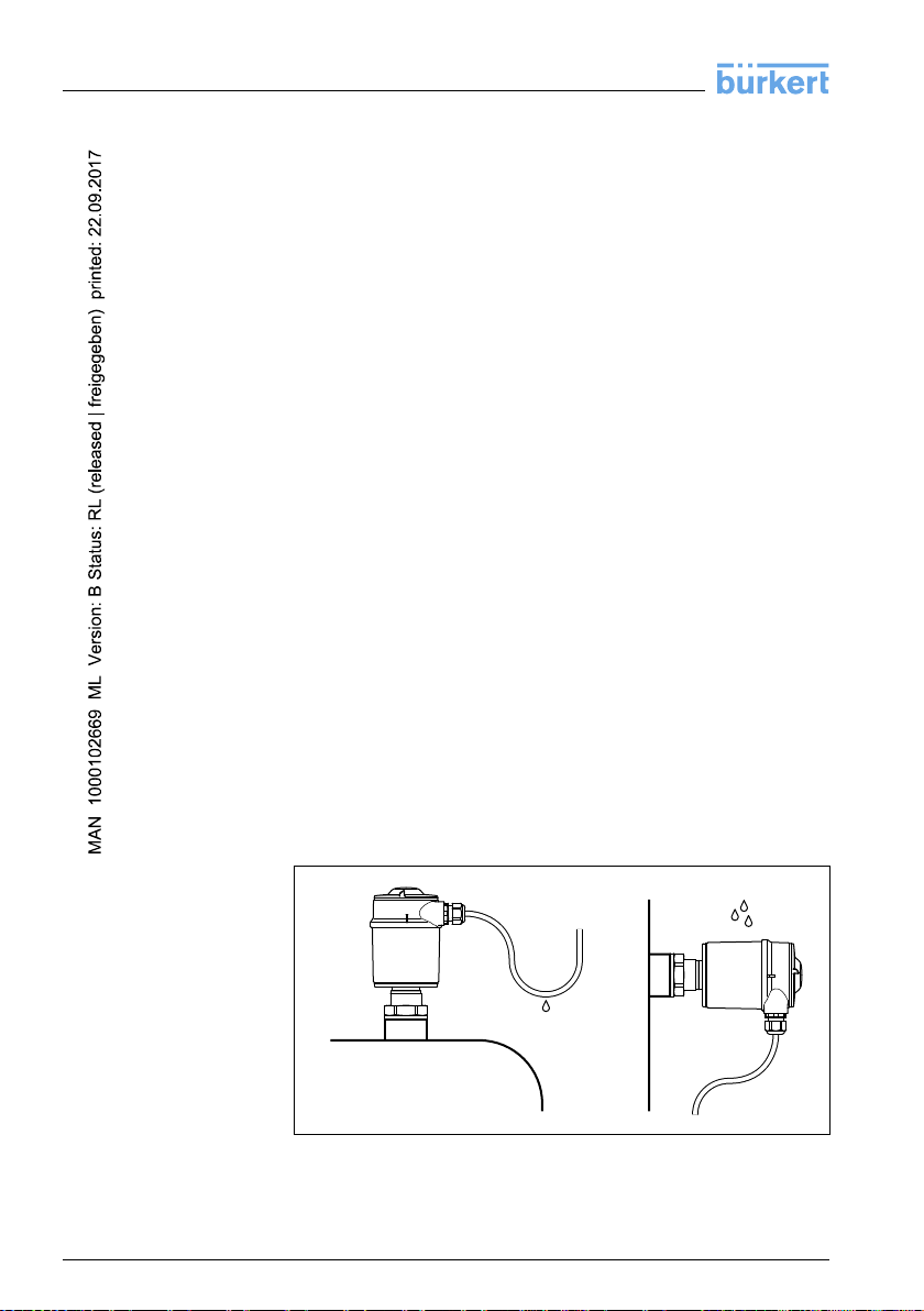
4.2Mounting instructions ........................ 11
5Connecting to power supply
5.1Preparing the connection ..................... 15
5.2Connection procedure........................ 16
5.3Wiring plan,single chamber housing ............. 17
6Set up with the indicating and adjustment module
6.1Short description ........................... 19
6.2Insert indicating and adjustment module........... 19
6.3Adjustment system .......................... 21
6.4Setup steps ............................... 22
6.5Menu schematic............................ 28
6.6Saving the parameter adjustment data............ 30
7Set up with PACTware and other adjustment programs
7.1Connecting the PC .......................... 31
7.2Parameter adjustment with PACTware ............ 31
7.3Parameter adjustment with AMS™and PDM . . . . . . . 32
7.4Saving the parameter adjustment data............ 32
8Maintenance and fault rectification
8.1Maintenance .............................. 33
8.2Rectify malfunctions ......................... 33
8.3Exchanging the electronics module .............. 34
2LEVEL TRANSMITTER 8186 •4…20 mA/HART two-wire
Contents
32342-EN-100506

8.4Instrument repair ........................... 34
9Dismounting
9.1Dismounting steps .......................... 36
9.2Disposal ................................. 36
10 Supplement
10.1Technical data ............................. 37
10.2Dimensions ............................... 47
Supplementary documentation
Information:
Supplementary documents appropriate to the ordered version come
with the delivery.You can find them listed in chapter "Product
description".
Instructions manuals for accessories and replacement parts
Tip:
Toensure reliable setup and operation of your LEVEL TRANSMITTER
8186,we offer accessories and replacement parts.The corresponding
documentations are:
lOperating instructions manual "Oscillator LEVEL TRANSMITTER
818X"
LEVEL TRANSMITTER 8186 •4…20 mA/HARTtwo-wire 3
Contents
32342-EN-100506

1About this document
1.1Function
This operating instructions manual provides all the information you
need for mounting,connection and setup as well as important
instructions for maintenance and fault rectification.Please read this
information before putting the instrument into operation and keep this
manual accessible in the immediate vicinity of the device.
1.2Target group
This operating instructions manual is directed to trained qualified
personnel.The contents of this manual should be made available to
these personnel and put into practice by them.
1.3Symbolism used
Information,tip,note
This symbol indicates helpful additional information.
Caution:Ifthis warning is ignored,faults or malfunctions can
result.
Warning:If this warning is ignored,injury to persons and/or serious
damage to the instrument can result.
Danger:If this warning is ignored,serious injury to persons and/or
destruction of the instrument can result.
Exapplications
This symbol indicates special instructions for Ex applications.
lList
The dot set in front indicates a list with no implied sequence.
àAction
This arrow indicates a single action.
1Sequence
Numbers set in front indicate successive steps in a procedure.
4LEVEL TRANSMITTER 8186 •4…20 mA/HART two-wire
1About this document
32342-EN-100506

2For your safety
2.1Authorised personnel
All operations described in this operating instructions manual must be
carried out only by trained specialist personnel authorised by the plant
operator.
During work on and with the device the required personal protective
equipment must always be worn.
2.2Appropriate use
LEVEL TRANSMITTER 8186 is a sensor for continuous level
measurement.
You can find detailed information on the application range in chapter
"Product description".
Operational reliability is ensured only if the instrument is properly used
according to the specifications in the operating instructions manual as
well as possible supplementary instructions.
For safety and warranty reasons,any invasive work on the device
beyond that described in the operating instructions manual may be
carried out only by personnel authorised by the manufacturer.Arbitrary
conversions or modifications are explicitly forbidden.
2.3Warning about misuse
Inappropriate or incorrect use of the instrument can give rise to
application-specific hazards,e.g.vessel overfill or damage to system
components through incorrect mounting or adjustment.
2.4General safety instructions
This is a high-tech instrument requiring the strict observance of
standard regulations and guidelines.The user must take note of the
safety instructions in this operating instructions manual,the country-
specific installation standards as well as all prevailing safety
regulations and accident prevention rules.
The instrument must only be operated in a technically flawless and
reliable condition.The operator is responsible for trouble-free
operation of the instrument.
During the entire duration of use,the user is obliged to determine the
compliance of the required occupational safety measures with the
current valid rules and regulations and also take note of new
regulations.
LEVEL TRANSMITTER 8186 •4…20 mA/HARTtwo-wire 5
2For your safety
32342-EN-100506

2.5Safety label on the instrument
The safety approval markings and safety tips on the device must be
observed.
2.6CE conformity
This device fulfills the legal requirements of the applicable EC
guidelines.By attaching the CE mark,we provide confirmation of
successful testing.
2.7Fulfillment of NAMUR recommendations
With regard to compatibility,LEVEL TRANSMITTER 8186 and its
indicating and adjustment components fulfill NAMUR recommendation
NE 53.
The parameter adjustment of the basic sensor functions is independ-
ent of the software version.The range of available functions depends
on the respective software version of the individual components.
The software version of LEVEL TRANSMITTER 8186 can be
determined as follows:
lon the type label of the electronics
lvia the indicating and adjustment module
Please contact us if you have questions concerning the software
history.
2.8Safety instructions for Ex areas
Please note the Ex-specific safety information for installation and
operation in Ex areas.These safety instructions are part of the
operating instructions manual and come with the Ex-approved
instruments.
6LEVEL TRANSMITTER 8186 •4…20 mA/HART two-wire
2For your safety
32342-EN-100506

3Product description
3.1Structure
The scope of delivery encompasses:
lLEVEL TRANSMITTER 8186 level sensor
lDocumentation
-this operating instructions manual
-Supplementary instructions manual "Safety Manual -Func-
tional safety according to IEC 61508 (SIL)"
-Operating instructions manual "Indicating and adjustment
module"(optional)
-Ex-specific"Safety instructions"(with Ex versions)
-if necessary,further certificates
The LEVEL TRANSMITTER 8186 consists of the components:
lProcess fitting with probe
lHousing with electronics
lHousing cover,optionally available with indicating and adjustment
module
1
2
3
Fig.1:LEVEL TRANSMITTER 8186 -rod version
1Housing cover with integrated indicating and adjustment module (optional)
2Housing with electronics
3Process fitting
The type label contains the most important data for identification and
use of the instrument:
Scope of delivery
Components
Type label
LEVEL TRANSMITTER 8186 •4…20 mA/HARTtwo-wire 7
3Product description
32342-EN-100506

lArticle number
lSerial number
lTechnical data
lArticle numbers,documentation
In addition to the type label outside on the instrument,you find the
serial number also inside the instrument.
3.2Principle of operation
LEVEL TRANSMITTER 8186 is a level sensor with cable or rod probe
for continuous level measurement.
It is designed for industrial use in all areas of process technology and
can be used in aggressive liquids.
High frequency microwave pulses are guided along a steel rope or a
rod.Upon reaching the product surface,the microwave pulses are
reflected.The running time is evaluated by the instrument and
outputted as distance.
Two-wire electronics 4…20 mA/HART for power supply and
measured value transmission over the same cable.
The supply voltage range can differ depending on the instrument
version.
The data for power supply are specified in chapter "Technical data".
3.3Operation
LEVEL TRANSMITTER 8186 can be adjusted with different adjust-
ment media:
lwith indicating and adjustment module
lWith a HART handheld
The entered parameters are generally saved in LEVEL TRANS-
MITTER 8186,optionally also in the indicating/adjustment module.
3.4Packaging,transport and storage
Your instrument was protected by packaging during transport.Its
capacity to handle normal loads during transport is assured by a test
according to DIN EN 24180.
The packaging of standard instruments consists of environment-
friendly,recyclable cardboard.For special versions,PE foam or PE foil
is also used.Dispose of the packaging material via specialised
recycling companies.
Transport must be carried out under consideration of the notes on the
transport packaging.Nonobservance of these instructions can cause
damage to the device.
Application area
Functional principle
Voltage supply
Packaging
Transport
8LEVEL TRANSMITTER 8186 •4…20 mA/HART two-wire
3Product description
32342-EN-100506

The delivery must be checked for completeness and possible transit
damage immediately at receipt.Ascertained transit damage or
concealed defects must be appropriately dealt with.
Up to the time of installation,the packages must be left closed and
stored according to the orientation and storage markings on the
outside.
Unless otherwise indicated,the packages must be stored only under
the following conditions:
lNot in the open
lDry and dust free
lNot exposed to corrosive media
lProtected against solar radiation
lAvoiding mechanical shock and vibration
lStorage and transport temperature see chapter "Supplement -
Technical data -Ambient conditions"
lRelative humidity 20 …85 %
Transport inspection
Storage
Storage and transport
temperature
LEVEL TRANSMITTER 8186 •4…20 mA/HARTtwo-wire 9
3Product description
32342-EN-100506

4Mounting
4.1General instructions
Make sure that all parts of the instrument exposed to the process,in
particular the sensor element,process seal and process fitting,are
suitable for the existing process conditions.These include above all
the process pressure,process temperature as well as the chemical
properties of the medium.
You can find the specifications in chapter "Technical data"or on the
type label.
Select an installation position you can easily reach for mounting and
connecting as well as later retrofitting of an indicating and adjustment
module.The housing can be rotated by 330°without the use of any
tools.You can also install the indicating and adjustment module in four
different positions (each displaced by 90°).
Before beginning the welding work,remove the electronics module
from the sensor.By doing this,you avoid damage to the electronics
through inductive coupling.
Use the recommended cables (see chapter "Connecting to power
supply")and tighten the cable gland.
You can give your instrument additional protection against moisture
penetration by leading the connection cable downward in front of the
cable entry.Rain and condensation water can thus drain off.This
applies mainly to outdoor mounting as well as installation in areas
where high humidity is expected (e.g.through cleaning processes)or
on cooled or heated vessels.
Fig.2:Measures against moisture penetration
Suitability for the proc-
ess conditions
Mounting position
Welding work
Moisture
10 LEVEL TRANSMITTER 8186 •4…20 mA/HART two-wire
4Mounting
32342-EN-100506

The reference plane for the measuring range of the sensors is the
lower edge of the flange.
Keep in mind that a min.distance must be maintained below the
reference plane and possibly also at the end of the probe -
measurement in these areas is not possible (dead band). Keep in mind
that the cable length cannot be used all the way to the end because
measurement in the area of the gravity weight is not possible.These
min.distances (dead bands)are listed in chapter "Technical data".
Keep in mind for the adjustment that the default setting for the
measuring range refers to water.
The process fitting must be sealed if there is gauge or low pressure in
the vessel.Before use,check if the seal material is resistant against
the measured product and the process temperature.
The max.permissible pressure is specified in chapter "Technical data"
or on the type label of the sensor.
4.2Mounting instructions
Mount LEVEL TRANSMITTER 8186 in such a way that the distance to
vessel installations or to the vessel wall is at least 300 mm (12 in).
During operation,the probe must not touch any installations or the
vessel wall.
In vessels with conical bottom it can be advantageous to mount the
sensor in the center of the vessel,as measurement is then possible
down to the lowest point of the vessel bottom.
Fig.3:Vessel with conical bottom
Measuring range
Pressure
Mounting position
LEVEL TRANSMITTER 8186 •4…20 mA/HARTtwo-wire 11
4Mounting
32342-EN-100506

To compensate the normal bias voltage loss due to the seal materials,
you have to use also disc springs in addition to the flange screws for
fastening PTFE plated flanges.
The flange screws of LEVEL TRANSMITTER 8186 must always be
tightened with a torque of approx.60 Nm(44 lbf ft)so that the PTFE
washer seals reliably.
If possible,avoid sockets.Mount the sensor flush with the vessel top.If
this is not possible,use short sockets with small diameter.
Higher sockets or sockets with a bigger diameter can generally be
used.They simply increase the upper dead band.Check if this is
relevant for your measurement.
In such cases,always carry out a gating out of false signals after
installation.You can find further information under "Setup procedure".
If a socket is absolutely necessary,then the use of a coax probe is
recommended.Due to the coax guide tube,sockets do not influence
measurement accuracy.
7 29/32"
3 15/16"
h
d
d h
DN40 ...DN150 ≤ 150 /
≤ 100 /> DN150 ...DN200
Fig.4:Mounting socket
Standpipes or bypass tubes are normally metal tubes with a diameter
of 30 …200 mm (1.18 …7.87 in). In measurement technology such a
tube corresponds to a coax probe.It does not matter if the standpipe is
perforated or slotted for better mixing.Lateral inlets with bypass tubes
also do not influence the measurement.
Measuring probes can be mounted in bypass tubes up to DN 200.
The max.temperature is 250 °C(482 °F).
IfLEVEL TRANSMITTER 8186 is used in standpipes or bypass tubes,
contact with the tube wall should be avoided.We offer spacers as
accessories for fastening the probe in the middle of the tube.
Torque with PTFE plated
flanges
Socket
Standpipes or bypass
tubes
12 LEVEL TRANSMITTER 8186 •4…20 mA/HART two-wire
4Mounting
32342-EN-100506

Depending on the tube diameter or tube length,one or several spacers
can be mounted.With cable probes,the cable can also be strained to
avoid contact with the tube.
The max.temperature for the spacers is 250 °C(482 °F).
Keep in mind that buildup can form on the spacers.Strong buildup can
influence the measurement.
Microwaves can penetrate plastics.For process technical reasons,
plastic standpipes are problematic.If durability is no problem,then we
recommend the use of metal standpipes.
1
Fig.5:Position of the spacer
1Spacer
Note:
Measurement in a standpipe is not recommended for very adhesive
products.
Make sure that the probe is not subjected to strong lateral forces.
Mount LEVEL TRANSMITTER 8186 at a position in the vessel where
no disturbances,e.g.from filling openings,agitators,etc., can occur.
Inflowing medium
LEVEL TRANSMITTER 8186 •4…20 mA/HARTtwo-wire 13
4Mounting
32342-EN-100506

Fig.6:Lateral load
14 LEVEL TRANSMITTER 8186 •4…20 mA/HART two-wire
4Mounting
32342-EN-100506

5Connecting to power supply
5.1Preparing the connection
Always keep in mind the following safety instructions:
lConnect only in the complete absence of line voltage
lIf overvoltage surges are expected,overvoltage arresters should
be installed
In hazardous areas you should take note of the appropriate
regulations,conformity and type approval certificates of the sensors
and power supply units.
Power supply and current signal are carried on the same two-wire
cable.The voltage supply range can differ depending on the
instrument version.
The data for power supply are specified in chapter "Technical data".
Provide a reliable separation between the supply circuit and the mains
circuits according to DIN VDE 0106 part 101.
Keep in mind the following additional influences on the operating
voltage:
lOutput voltage of the power supply unit can be lower under
nominal load (with a sensor current of 20.5mAor 22 mAin case of
fault message)
lInfluence of additional instruments in the circuit (see load values in
chapter "Technical data")
The instrument is connected with standard two-wire cable without
screen.If electromagnetic interference is expected which is above the
test values of EN 61326 for industrial areas,screened cable should be
used.
Use cable with round cross-section.Acable outer diameter of 5…9mm
(0.2…0.35 in)ensures the seal effect of the cable gland.If you are
using cable with a different diameter or cross-section,exchange the
seal or use a suitable cable gland.
If screened cable is necessary,connect the cable screen on both ends
to ground potential.In the sensor,the screen must be connected
directly to the internal ground terminal.The ground terminal on the
outside of the housing must be connected to the potential equalisation
(low impedance).
If potential equalisation currents are expected,the connection on the
processing side must be made via a ceramic capacitor (e.g.1nF,
1500 V). The low frequency potential equalisation currents are thus
suppressed,but the protective effect against high frequency interfer-
ence signals remains.
Note safety instructions
Take note of
safety instruc-
tions for Ex ap-
plications
Voltage supply
Connection cable
Cable screening and
grounding
LEVEL TRANSMITTER 8186 •4…20 mA/HARTtwo-wire 15
5Connecting to power supply
32342-EN-100506

Take note of the corresponding installation regulations for Ex
applications.In particular,make sure that no potential equalisation
currents flow over the cable screen.In case of grounding on both sides
this can be achieved by the use of a capacitor or a separate potential
equalisation.
5.2Connection procedure
Proceed as follows:
1Unscrew the housing cover
2If an indicating and adjustment module is installed,remove it by
turning it slightly to the left.
3Loosen compression nut of the cable entry
4Remove approx.10 cm (4in)of the cable mantle,strip approx.
1cm (0.4in)of insulation from the ends of the individual wires
5Insert the cable into the sensor through the cable entry
6Lift the opening levers of the terminals with a screwdriver (see
following illustration)
Fig.7:Connection steps 6and 7
7Insert the wire ends into the open terminals according to the wiring
plan
8Press down the opening levers of the terminals,you will hear the
terminal spring closing
Connection ca-
ble for Ex appli-
cations
16 LEVEL TRANSMITTER 8186 •4…20 mA/HART two-wire
5Connecting to power supply
32342-EN-100506

9Check the hold of the wires in the terminals by lightly pulling on
them
10 Connect the screen to the internal ground terminal,connect the
outer ground terminal to potential equalisation
11 Tighten the compression nut of the cable entry.The seal ring must
completely encircle the cable
12 Screw the housing cover on
The electrical connection is finished.
5.3Wiring plan,single chamber housing
The following illustrations apply to the non-Exas well as to the Ex-ia
version.
I²C
Display
1 2 5 6 7 8
3
4
1
2
Fig.8:Electronics and connection department,single chamber housing
1Service interface
2Spring-loaded terminals for connection of an external indication
3Ground terminal for connection of the cable screen
4Spring-loaded terminals for voltage supply
Electronics and connec-
tion compartment
LEVEL TRANSMITTER 8186 •4…20 mA/HARTtwo-wire 17
5Connecting to power supply
32342-EN-100506

I2C
Display
1
1 2 5 6 7 8
Fig.9:Wiring plan,single chamber housing
1Voltage supply/Signal output
Wiring plan
18 LEVEL TRANSMITTER 8186 •4…20 mA/HART two-wire
5Connecting to power supply
32342-EN-100506

6Set up with the indicating and adjustment
module
6.1Short description
The indicating and adjustment module is used for measured value
indication,adjustment and diagnoses.It can be used in all sensors of
the LEVEL TRANSMITTER family.
From a hardware version …- 01 or higher of the indicating and
adjustment module,i.e.the corresponding sensor electronics,an
integrated backlight can be switched on via the adjustment menu.The
hardware version is stated on the type label of the indicating and
adjustment module or the sensor electronics.
Note:
You can find detailed information on the adjustment in the operating
instructions manual "Indicating and adjustment module".
6.2Insert indicating and adjustment module
The indicating and adjustment module can be inserted into the sensor
and removed again at any time.It is not necessary to interrupt the
power supply.
For installation,proceed as follows:
1Unscrew the housing cover
2Place the indicating and adjustment module in the desired position
on the electronics (you can choose any one of four different
positions -each displaced by 90°)
3Press the indicating and adjustment module onto the electronics
and turn it to the right until it snaps in.
4Screw housing cover with inspection window tightly back on
Removal is carried out in reverse order.
The indicating and adjustment module is powered by the sensor,an
additional connection is not necessary.
Function/Configuration
Mount/Dismount indicat-
ing and adjustment
module
LEVEL TRANSMITTER 8186 •4…20 mA/HARTtwo-wire 19
6Set up with the indicating and adjustment module
32342-EN-100506

Fig.10:Insert indicating and adjustment module
Note:
If you intend to retrofit the instrument with an indicating and adjustment
module for continuous measured value indication,a higher cover with
an inspection glass is required.
20 LEVEL TRANSMITTER 8186 •4…20 mA/HART two-wire
6Set up with the indicating and adjustment module
32342-EN-100506
Table of contents
Languages:
Popular Laser Level manuals by other brands

ADA INSTRUMENTS
ADA INSTRUMENTS 2D Basic Level operating manual

Stabila
Stabila TECH 196-2 Electronic Series operating instructions

Bauer
Bauer 20204L-B Owner's manual & safety instructions

Agatec
Agatec LT 200 owner's manual

Stanley
Stanley CL2XTi manual

LaserLiner
LaserLiner MultiBeam-Laser MBL 3 operating instructions