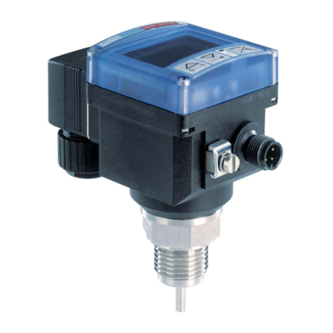
Burkert 8625-2 User manual

Operating Instructions
Bedienungsanleitung
Manuel d‘utilisation
Type 8625-2
Standard
Compact Temperature Controller
Kompakter Temperaturregler
Régulateur compact de température

We reserve the right to make technical changes without notice.
Technische Änderungen vorbehalten.
Sous réserve de modifications techniques.
© Bürkert Werke GmbH & Co. KG, 200 - 2017
Operating Instructions 1706/_EU-EN_008 / Original DE

8625-2 Standard - 1
english
1 GENERAL NOTES ................................................................................................................ 3
1.1 Symbols..................................................................................................................................................... 3
1.2 Safety notes .......................................................................................................................................... 3
1.3 Protection from damage by electrostatic charging .......................................... 4
2 FUNCTION ....................................................................................................................................... 5
3 APPLICATION AREA ....................................................................................................... 6
4 TECHNICAL DATA................................................................................................................ 7
5 COMMISSIONING.................................................................................................................. 8
5.1 Connection to the proportional valve............................................................................. 8
5.2 Changing the cable outlet direction ................................................................................. 9
5.3 Connection configuration on the temperature controller
type 8625-2 .......................................................................................................................................... 10
5.4 First commissioning.................................................................................................................... 12
6 OPERATING THE TEMPERATURE CONTROLLER
TYPE ...................................................................................................................................................... 13
6.1 Operating modes ............................................................................................................................ 13
6.2 Indications on the display ..................................................................................................... 14
6.3 Key allocation .................................................................................................................................... 15
6.4 Standard mode ................................................................................................................................. 16
6.4.1 Standard mode and internal setpoint............................................................. 16
6.4.2 Standard mode and external setpoint ........................................................... 17
6.5 Manual mode ..................................................................................................................................... 18
6.6 Configuration mode ...................................................................................................................... 19
6.6.1 Menu of configuration mode ................................................................................. 21
6.6.2
UNIT
- setting of unit of temperature ............................................................... 22
CONTENTS

2 - 8625-2 Standard
english
6.6.3
MODE
- setting of setpoint mode ....................................................................... 23
6.6.4
AMPL
- setting of amplification Kp............................................................................... 25
6.6.5
INTG
- setting of reset time TN.......................................................................................... 26
6.6.6
INV
- heating (non-inverted control)/cooling
(inverted control) ............................................................................................... 31
6.6.7
ZERO
- zero point switch-off .................................................................................. 32
6.6.8
VALV
- adaptation of controller output signal ........................................... 33
6.6.9
END
- storage of the values ................................................................................... 35
6.7 Settings on delivery .................................................................................................................... 36
7 ERROR MESSAGES....................................................................................................... 37

8625-2 Standard - 3
english
1 GENERAL NOTES
Please observe the notes in these operating instructions together with the
conditions of use and permitted data that are specified in the data sheets of the
proportional valve used and of the controller type 8625-2, in order that the
device will function perfectly and remain operable for a long time:
• Keep to standard engineering rules in planning the use of and operating the
device!
• Interference with the device is only allowed by specialist personnel using
suitable tools!
• Observe the current regulations on accident prevention and safety for
electrical devices during operation, maintenance and repair of the device!
• Before interfering with the system, always switch off the voltage!
• Take suitable precautions to prevent unintended operation or damage by
unauthorized action!
• On non-observance of this note and unauthorized interference with the
device, we will refuse all liability and the guarantee on device and
accessories will become void!
1.1 Symbols
The following symbols are used in these operating instructions:
marks a work step that you must carry out.
ATTENTION! marks notes on whose non-observance your health or the
functioning of the device will be endangered.
NOTE marks important additional information, tips and
recommendations.
1.2 Safety notes

4 - 8625-2 Standard
english
1.3 Protection from damage by electrostatic charging
ATTENTION
EXERCISE CAUTION ON HAND-
LING !
ELECTROSTATICALLY
SENSITIVE
COMPONENTS/MODULES
This device contains electronic components that are sensitive to electrostatic
discharge (ESD). Contact to electrostatically charged persons or objects will
endanger these components. In the worst case, they will be immediately
destroyed or will fail after commissioning.
Observe the requirements of EN 100 015 - 1 in order to minimize the
possibility of, or avoid, damage from instantaneous electrostatic discharge.
Also take care not to touch components that are under supply voltage.

8625-2 Standard - 5
english
2 FUNCTIONS
The temperature controller type 8625-2 is designed, in connection with a pro-
portional valve and a temperature sensor, to keep the temperature in a flowing
medium constant or to follow a given setpoint profile.
The functionality of the device is characterized by:
• Compact design, capable of direct installation on the proportional valve.
• May be combined with valve types 6022, 6023, 6024, 6223, 2832, 2834.
• Controller ouput directly to proportional valve in the form of a PWM signal;
this minimizes hysteresis and optimizes the control performance.
• Connection of PT100 sensor of any type to the actual value input (e.g.
types ST20 - 24).
• The standard signal input can be scaled to the control range actually
required (standard model only).
• Setting of setpoint value via standard 4 - 20 mA or 0 - 10 V signal, keypad
or bus.
• Digital control with a PI control algorithm and settable control parameters.
• Applications in heating and cooling possible.
• Display of setpoint or actual values (to choice) on an LCD display.
• Configuration with three keys.
For measured variables such as pressure, flow rate, conductivity,etc. we offer
suitable controllers, e.g:
• Type 8623-2 for flow rate control with frequency input for the sensor
• Type 8624-2 for pressure, flow rate, conductivity,etc. with standard
signal input for connection of a transmitter.

6 - 8625-2 Standard
english
3 APPLICATION AREA
The compact temperature controller type 8625-2 is used in the area of mixing
temperature control.
Setpoint
cold hot
Proportional valve
Temperature sensor PT 100
Medium with controlled temperature
Fig.: Structure of a temperature control system with the compact temperature
controller type 86235-2 (schematic)
Actual value (PT100)
Controller type 8625-2

8625-2 Standard - 7
english
Operating voltage 24 V DC
Power consumption max. 0.3 W (without proportional valve)
Output current (to valve) max. 1.0 A
Operating temperature - 10 °C ... + 60 °C / 14 °F ... 140 °F
Interference resistance to EN50082-2
Interference emission to EN50081-2
Inputs
Sensor input PT100
temperatur range - 50 °C ... 150 °C / - 58 °F ... 302 °F
resolution 0.25 °C or 0.45 °F 1)
precision 1.5 °C bzw 2.7 °F 1)
1 standard signal input 4 - 20 mA / 0 - 10 V, adjustable
resolution 10 Bit
input impedance (4 - 20 mA) < 200 Ω
input impedance (0 - 10 V) > 300 kΩ
Output
PWM output 24 V - pulse width modulated
Controller
Control algorithm PI control
Scan time TA50 ms
Amplification factor Kp0,00 - 10,00 %/K
Reset time TN0,1 - 200,1 s
Scaling -50 °C ... 150 °C or -58 °F ... 302 °F
Housing
Cable outlet rotatable in 90° steps
System of protection IP 65
Material polyamide
Dimensions (WxHxD) 54 x 54 x 61 mm
Order no. 143 571
1) Calibrated to 1 m conductor length and 0.5 mm² conductor cross-section.
4 TECHNISCHE DATEN

8 - 8625-2 Standard
english
5 COMMISSIONING
NOTE Interference with the device is only allowed by specialist
personnel using suitable tools!
Before interfering with the temperature controller, always
switch off the voltage!
On screwing the temperature controller onto the proportional
valve, make sure the seal is correctly seated!
ÎUnscrew the 4 screws on the front panel of the temperature controller and
remove the cover carefully.
ÎPlace the housing of the temperature controller with the seal onto the valve.
ÎScrew the temperature controller tightly to the valve.
5.1 Connecting to the proportional valve
ÎPlace the conver on the temperature controller and screw it tight with the 4
screws
Fig.: Connecting the temperature controller to the proportional valve
ATTENTION! Make sure the cover is placed on the right way round
(pinned strips must engage in the sockets).
ATTENTION!

8625-2 Standard - 9
english
5.2 Changing the cable outlet direction
ÎUnscrew the 4 screws on the front panel
of the temperature controller and remove
the cover carefully.
ÎRemove the screw to the valve and
remove the plastic cross.
ÎDetach the plate from the cube.
ÎPull out the cube downwards and replace
in the desired orientation.
ÎPlace the plate onto the cube (the pins
must engage in the guides).
ÎLay on the plastic cross and insert the
screw through the cube.
ÎConnect the temperature controller to the
proportional valve (see 5.1).

10 - 8625-2 Standard
english
M12 (4-pole): Supply voltage and standard signal for setpoint
Configuration:
1 PT100 supply (0.5 mA)
3 GND
4 Temperature input PT100
* wire colours when using standard cables
with M8 plug (3-pole)
1 (brown)*4 (black)
3 (blue) 2 (white) Configuration:
1 24 V DC supply voltage
2 Standard signal input, external setpoint
3 GND external setpoint
4 GND supply voltage
* wire colours when using standard cables
with M12 plug (4-pole)
M8 (PT100-input):
1 (brown)
4 (black)
3 (blue)*
5.3 Connection configuration of temperature controller
type 8625-2
Fig.: Connections on temperature controller type 8625-2
M8, 3-pole
PT100 input
M12, 4-pole
Supply voltage
and standard
signal input
External setpoint

8625-2 Standard - 11
english
connection of temperature sensor PT 100
Temperature
sensor PT 100
Fig.: Connecting temperature sensor PT 100 to type 8625-2
1
(brown)
4 (black)
3 (blue)
Type 8625-2 temperature controller
M8 (3-pole)
ATTENTION! Do not connect a voltage to pin 1 of the 3-pole plug! Pin 1
is a 0.5 mA output to supply the sensor (PT100)
12
Bridge pin 1 and pin 4 of
temperature controller directly at
the temperature sensor PT100 and
connect to pin 1 of PT100.
Connect pin 3 of temperature
controller to pin 2 of temperature
sensor PT100.

12 - 8625-2 Standard
english
5.4 First commissioning
Settings absolutely necessary on first commissioning
• Type and range of standard signal (4 - 20 mA or 0 - 10 V) with external
setpoint.
• Lower limit for correcting variable (controller output), (see 6.6.8 VALV).

8625-2 Standard - 13
english
6 OPERATING THE TEMPERATURE CONTROLLER TYPE
8625-2
Three modes are possible for operating the temperature controller type 8625-2:
• Standard mode
• Configuration mode
• Manual mode
Standard
Mode
Manual
mode
press key briefly
press key for 5 sec.
Configuration
Mode
Menu
.
.
.
END
press key
6.1 Operating modes
Fig.: Switching between operating modes

14 - 8625-2 Standard
english
4-digit display to
indicate the
process values ans
parameters
Manual
mode
Indication of specified setpoint value
- internal setpoint (no display)
- external setpoint (1)
- setpoint via bus (1)
4-digit text display, e.g.
of temperature unit in
°C or °F.
6.2 Indications on the display
Fig.: Display of the compact temperature controller type 8625-2
NOTE • After the supply voltage is switched on, the controller is in
the standard mode.
• Change to the other modes is possible by the actions
shown in the figure.
• After the configuration mode is ended, the parameters set
are transferred to the memory of the controller.
• After the operating voltage is switched off, the parameters
last active are stored; on next switching on again, these will
be active again.
Bus active

8625-2 Standard - 15
english
6.3 Key allocation
Mode
press key:
switchover of display
between set and
actual value
press key:
open valve
(inc)
press key:
backwards in menu
press key:
increase the selected
digit*
press key:
switchover of display
between set and actual
value
press key:
close valve
(dec)
press key:
forwards in menu
press key briefly:
to next digit
press key for 2 sec:
set decimal point
behind the place
selected ***
press key briefly:
enters manual mode
press key for 5 sec:
enters configuration
mode
press key briefly:
back to standard mode
press key:
to edit the menu item
press key:
concludes setting,
back to menu item**
Standard mode
Manual mode
Configuration
mode
Menu items
Configuration
mode
Edititing menu
items
* In the menu item
VALV
, setting is not digit-by-digit but in increasing
sequence within the limits 00 ... 100.
** The values set are transferred to the memory.
*** In the
MODE
mode, a change of sign is possible at the 4th place from the
right.
No function on this model
ENTER-keykey
"DEC"
key
"INC"
NOTE The values set are valid for current control procedure only after
the configuration mode has been left in the menu item END with
the key.

16 - 8625-2 Standard
english
6.4 Standard mode
Fig.: Possible display in standard mode with internal setpoint
In this mode, the device works after switching on the operating voltage. The
current temperature is now indicated.
6.4.1 Standard mode and internal setpoint
Display of actual value (°C)
Setting internal
setpoint
Display of setpoint value (°C)
In this mode, the setpoint is specified via the keys of the display.

8625-2 Standard - 17
english
6.4.2 Standard mode and external setpoint
Fig.: Possible display in standard mode with external setpoint
Display of actual value ( °C)
Setting external setpoint
Display of setpoint value (°C)
1
Here the controller receives the setpoint value via the 4 - 20 mA or 0 - 10 V signal
present on pins 2 ans 3 of the 4-pole M12 plug.

18 - 8625-2 Standard
english
ÎAfter switching to the manual mode,
the current actual value is displayed.
manual mode activated
Display of actual value
Fig.: Displayed after switching to the manual mode
The display
0 %
corresponds to the minimum pulse-duty factor
of the PWM signal set in the menu item
VALV
: 100 %
corresponds to a pulse-duty factor of 100 %.
NOTE
Display of the pulse-duty factor of the valve
Display in manual mode
As soon as the correcting variable is
changed by pressing the key or
key, the display switches
automatically to the value of the
correcting variable. After releasing the
key, the curent value is shown again.
ÎWith this key you increase the pulse-duty factor of the proportional
valve, i.e. the latter opens up to a max. of 100 %.
ÎWith this key you reduce the pulse-duty factor of the proportional
valve.
ÎPress the key in the manual mode. On release of the key, you
will return to the standard mode.
6.5 Manual mode
The manual mode can be activated from the standard mode by briefly pressing
the key.
In the manual mode there is no control: the value of correcting variable last
calculated is a first retained. By pressing the arrow keys, the correcting variable
can be increased or decreased.
Fig.: Display of the pulse-duty factor of the valve
Table of contents
Languages:
Other Burkert Temperature Controllers manuals
Popular Temperature Controllers manuals by other brands

Automationdirect.com
Automationdirect.com SOLO SLM Series user manual

MULTISPAN
MULTISPAN UTC-321P quick start guide

Auber Instruments
Auber Instruments WS Series Operation & instruction manual

Siemens
Siemens RDE10 Series manual

ABB
ABB TSP341-N Detailed installation instructions

Resol
Resol DeltaSol BS/2 manual

Stafford Instruments
Stafford Instruments ST325 User handbook

Mitsubishi Electric
Mitsubishi Electric EHPT20 Series Operation manual

Visonic
Visonic TMD-560 PG2 installation instructions

Mitsubishi
Mitsubishi A1S62TCTT-S2 user manual

KIOUR
KIOUR TOUCH RSD3 quick start guide

AKO
AKO AKO-D14120 installation instructions