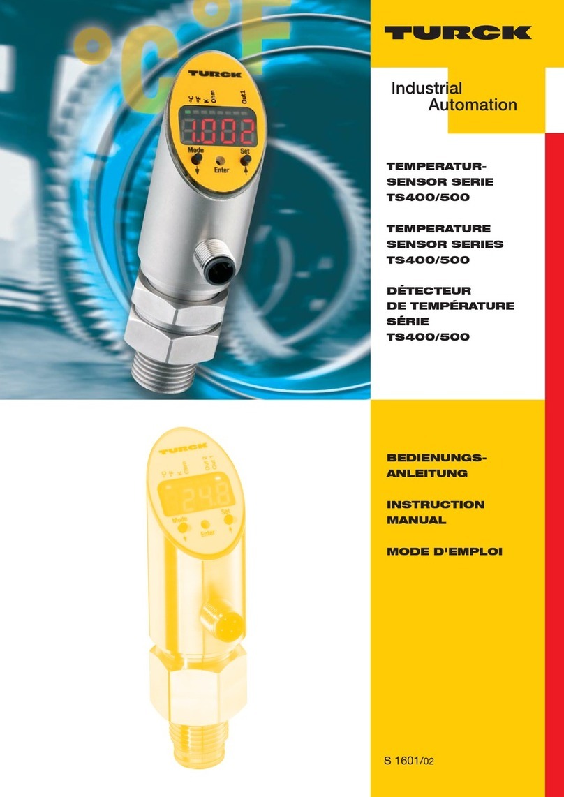
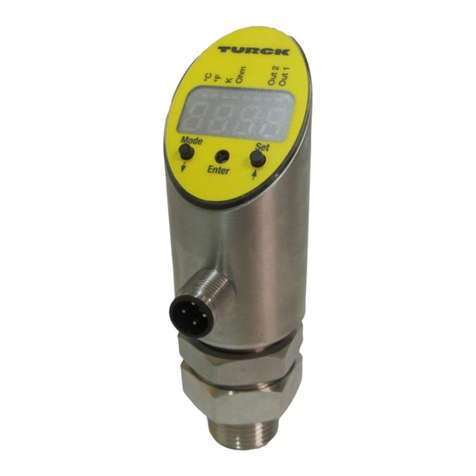
turck TS720 Series User manual

Your Global Automation Partner
Instructions for Use
TS720…
Temperature Processing
and Display Unit

Contents
Hans Turck GmbH & Co. KG | T +49 208 4952-0 | [email protected] | www.turck.com V01.00 | 2022/06 | 2
Contents
1 About these instructions ...................................................................................................................4
1.1 Target groups ...................................................................................................................4
1.2 Explanation of symbols used.........................................................................................4
1.3 Other documents.............................................................................................................4
1.4 Feedback about these instructions ..............................................................................4
2 Notes on the product .........................................................................................................................5
2.1 Product identification .....................................................................................................5
2.2 Scope of delivery..............................................................................................................5
2.3 Turck service .....................................................................................................................5
3 For your safety.....................................................................................................................................6
3.1 Intended use .....................................................................................................................6
3.2 Obvious misuse ................................................................................................................6
3.3 General safety instructions ............................................................................................6
4 Product description ............................................................................................................................7
4.1 Device overview...............................................................................................................7
4.2 Properties and features ..................................................................................................7
4.3 Operating and display functions ..................................................................................7
4.4 Operating principle .........................................................................................................7
4.5 Functions and operating modes...................................................................................8
4.5.1 Setting options..................................................................................................................................8
4.5.2 Normal operation — run mode ..................................................................................................8
4.5.3 Programming mode........................................................................................................................8
4.5.4 Output functions — switching output.....................................................................................9
4.5.5 Output functions – analog output.......................................................................................... 10
4.5.6 IO-Link mode................................................................................................................................... 12
4.5.7 SIO mode (standard I/O mode) ................................................................................................ 12
4.5.8 Auto detect function.................................................................................................................... 12
4.6 Technical accessories ................................................................................................... 13
4.6.1 Connectivity accessories............................................................................................................. 13
4.6.2 Temperature probe ...................................................................................................................... 14
4.6.3 Compression fittings and thermowells................................................................................. 16
5 Installing ............................................................................................................................................ 18
6 Connection ........................................................................................................................................ 19
6.1 Wiring diagrams............................................................................................................ 20
6.2 Wiring diagrams – Temperature probes .................................................................. 21
6.3 Connection instructions for thermocouples ........................................................... 22
6.4 Connection instructions for resistance thermometers.......................................... 22
7 Commissioning................................................................................................................................. 23
8 Operation........................................................................................................................................... 24
8.1 LEDs — operation ......................................................................................................... 24
8.2 Display indications ....................................................................................................... 25
9 Setting and parameterization ....................................................................................................... 26
9.1 Settable functions and properties............................................................................. 26
9.2 Setting via touchpads .................................................................................................. 27

Contents
Hans Turck GmbH & Co. KG | T +49 208 4952-0 | [email protected] | www.turck.com V01.00 | 2022/06 | 3
9.2.1 Locking the device........................................................................................................................ 31
9.2.2 Unlocking the device ................................................................................................................... 31
9.2.3 Setting parameter values via touchpads.............................................................................. 31
9.2.4 Protecting the sensor with a password................................................................................. 32
9.2.5 Parameters in the main menu .................................................................................................. 33
9.2.6 Parameters in the EF (Extended Functions) submenu..................................................... 35
9.3 Setting via IO-Link ........................................................................................................ 37
10 Troubleshooting............................................................................................................................... 38
11 Maintenance ..................................................................................................................................... 39
12 Repair ................................................................................................................................................. 39
12.1 Returning devices ......................................................................................................... 39
13 Disposal.............................................................................................................................................. 39
14 Technical data................................................................................................................................... 40
15 Turck subsidiaries — contact information.................................................................................. 42

About these instructions
Feedback about these instructions
Hans Turck GmbH & Co. KG | T +49 208 4952-0 | [email protected] | www.turck.com V01.00 | 2022/06 | 4
1 About these instructions
These instructions for use describe the structure, functions and the use of the product and will
help you to operate the product as intended. Read these instructions carefully before using the
product. This is to avoid possible damage to persons, property or the device. Retain the instruc-
tions for future use during the service life of the product. If the product is passed on, pass on
these instructions as well.
1.1 Target groups
These instructions are aimed at qualified personal and must be carefully read by anyone
mounting, commissioning, operating, maintaining, dismantling or disposing of the device.
1.2 Explanation of symbols used
The following symbols are used in these instructions:
DANGER
DANGER indicates a dangerous situation with high risk of death or severe injury if
not avoided.
WARNING
WARNING indicates a dangerous situation with medium risk of death or severe in-
jury if not avoided.
CAUTION
CAUTION indicates a dangerous situation of medium risk which may result in minor
or moderate injury if not avoided.
NOTICE
NOTICE indicates a situation which may lead to property damage if not avoided.
NOTE
NOTE indicates tips, recommendations and useful information on specific actions
and facts. The notes simplify your work and help you to avoid additional work.
uCALL TO ACTION
This symbol denotes actions that the user must carry out.
aRESULTS OF ACTION
This symbol denotes relevant results of actions.
1.3 Other documents
Besides this document, the following material can be found on the Internet at www.turck.com:
nData sheet
nDeclarations of conformity
nCommissioning manual IO-Link devices
1.4 Feedback about these instructions
We make every effort to ensure that these instructions are as informative and as clear as pos-
sible. If you have any suggestions for improving the design or if some information is missing in
the document, please send your suggestions to [email protected].

Notes on the product
Turck service
Hans Turck GmbH & Co. KG | T +49 208 4952-0 | [email protected] | www.turck.com V01.00 | 2022/06 | 5
2 Notes on the product
2.1 Product identification
These instructions apply to the following temperature processing and display units:
nTS720-2UPN8-H1141
nTS720-LI2UPN8-H1141
TS Operating principle
Operating principle
TS Temperature sensor
7 2 0 Mechanical design –
Display
012-segment display
Mechanical design
2Without process
connection
Design
7Compact device
H1 1 4 1 Electrical connection:
Male connector
Assignment
1Standard-compliant
assignment
Number of contacts
44 contacts
Orientation
1Straight
Design
H1 Male connector M12 × 1
LI2UPN8 Electrical version –
Electrical version
LI2UPN8 Analog and switching
outputs, voltage range
17…33 VDC
2UPN8 2 switching outputs,
voltage range
10…33 VDC
TS 7 2 0 – LI2UPN8 – H 1 1 4 1
2.2 Scope of delivery
The scope of delivery includes:
nTemperature processing and display unit
nQuick Start Guide
2.3 Turck service
Turck supports you with your projects, from initial analysis to the commissioning of your applic-
ation. The Turck product database under www.turck.com contains software tools for program-
ming, configuration or commissioning, data sheets and CAD files in numerous export formats.
The contact details of Turck subsidiaries worldwide can be found on p. [}42].

For your safety
General safety instructions
Hans Turck GmbH & Co. KG | T +49 208 4952-0 | [email protected] | www.turck.com V01.00 | 2022/06 | 6
3 For your safety
The product is designed according to state-of-the-art technology. However, residual risks still
exist. Observe the following warnings and safety notices to prevent damage to persons and
property. Turck accepts no liability for damage caused by failure to observe these warning and
safety notices.
3.1 Intended use
The compact processing and display units of the TS720… product series are designed for meas-
uring temperatures in machines and plants. This requires the connection of a temperature
probe to the devices. The temperature processing and display units support the connection of
resistance thermometers (RTD) and thermocouples (TC).
The devices may only be used as described in these instructions. Any other use is not in accord-
ance with the intended use. Turck accepts no liability for any resulting damage.
3.2 Obvious misuse
nThe devices are not safety components and must not be used for personal or property
protection.
3.3 General safety instructions
nThe device meets the EMC requirements for industrial areas. When used in residential areas,
take measures to avoid radio interference.
nThe device may only be assembled, installed, operated, parameterized and maintained by
professionally-trained personnel.
nThe device may only be used in accordance with applicable national and international regu-
lations, standards and laws.
nOnly operate the device within the limits stated in the technical specifications.

Product description
Operating principle
Hans Turck GmbH & Co. KG | T +49 208 4952-0 | [email protected] | www.turck.com V01.00 | 2022/06 | 7
4 Product description
The temperature processing and display units of the TS+ series are contained in a metal hous-
ing and provided with a G1/2” process connection. The sensor head can also be rotated by 340°
after installation. The devices have a metal M12 connector (male) for connecting the sensor
cable. Another M12 connector (female) is provided for connecting resistance thermometers
(RTD) and thermocouples (TC).
Devices with the following output functions are available:
nTS…LI2UPN…: 2 switching outputs (PNP/NPN/Auto) or 1 switching output (PNP/NPN/Auto)
and 1 analog output (I/U/Auto)
nTS…2UPN…: 2 switching outputs (PNP/NPN/Auto)
4.1 Device overview
30
112.1 [4.41]
Ø 38 [1.50]
Ø 18 [0.71]
G 1/2
55.1 [2.17]
12.2 [0.48]
M12 × 1
Electrical Connection
Temperature Probe (RTD, TC)
Electrical Connection
(PLC)
Fig.1: Dimensions in mm [inch]
4.2 Properties and features
nProcessing unit for connecting resistance thermometers (RTD) and thermocouples (TC)
nAutomatic probe detection
n4-digit, 2-colored, 12-segment display, rotatable by 180°
nUpper part of housing can be rotated up to 340°
nVarious IO-Link mapping profiles selectable
4.3 Operating and display functions
The front of the device is provided with three touchpads [ENTER], [MODE] and [SET], a 4-digit
12-segment multicolor display and status LEDs. This enables the user to set all essential func-
tions and properties directly on the device and read the actual process values and set switching
points.
4.4 Operating principle
Standard Pt100 and Pt1000 resistance thermometers (RTD) as well as thermocouples (TC) can
be connected to the temperature display and processing unit. The temperature value meas-
ured on the attached probe is passed on to the higher-level I/O. The device display shows the
temperature value in the unit selected by the user.

Product description
Functions and operating modes
Hans Turck GmbH & Co. KG | T +49 208 4952-0 | [email protected] | www.turck.com V01.00 | 2022/06 | 8
4.5 Functions and operating modes
Type Output
TS…LI2UPN… 2 switching outputs (PNP/NPN/Auto) or 1 switching output (PNP/NPN/
Auto) and 1 analog output (I/U/Auto)
TS…2UPN… 2 switching outputs (PNP/NPN/Auto)
A window function or a hysteresis function can be set for the switching outputs. The measuring
range of the analog output can be defined as required. The measured temperature can be
displayed in °C, °F or K, or the resistance can be displayed in Ω if a resistance thermometer is
connected. The devices can be parameterized via IO-Link and via touchpads. The following
temperature probes can be connected to the device:
nResistance thermometers (RTD)
– Pt100 (2-, 3-, 4-wire)
– Pt1000 (2-, 3-, 4-wire)
nThermocouples (TC)
– Type K, B, E, J, N, R, S and T
4.5.1 Setting options
The devices have three setting options:
nSetting via IO-Link
nSetting via touchpads
nSetting via FDT/DTM
4.5.2 Normal operation — run mode
The device detects the temperature on the probe and shows the required switching or analog
behavior according to the factory-set or customer-specific parameters. The display indicates
the process temperature present, the selected unit and the status of the switching outputs.
4.5.3 Programming mode
When the sensor is unlocked, the display will go into programming mode after the user presses
the [MODE] touch pad. In programming mode, all parameters and their corresponding values
can be read out and changed. The values for a parameter are displayed by briefly pressing the
[ENTER] touch pad. The [MODE] and [SET] touch pads are used to navigate within programming
mode. For more information, refer to the chapter “Setting and parameterization.”

Product description
Functions and operating modes
Hans Turck GmbH & Co. KG | T +49 208 4952-0 | [email protected] | www.turck.com V01.00 | 2022/06 | 9
4.5.4 Output functions — switching output
A window function and a hysteresis function can be set for the switching outputs.
Window function
The window function is used to set a switching range in which the switching output takes on a
defined switching state. The switching range is defined by means of an upper (FH) and lower
limit (FL). The minimum distance between the limits is 0.2K. If the upper limit is changed, the
lower limit value is adjusted automatically.
0
1
FL
FH
1
0
Fno
Fnc
t
T
acceptable
range
Fig.2: Behavior of the switching output – Window function
Hysteresis function
The hysteresis function is used to set a stable switching state around a setpoint that is inde-
pendent of system-related temperature fluctuations. The switching range is defined by means
of a switching point (SP) and a release point (rP). The minimum hysteresis is 0.2K. If the switch-
ing point is changed, the release point is adjusted automatically.
0
1
rP
SP
1
0
Hno
Hnc
t
T
hysteresis
Fig.3: Behavior of the switching output (hysteresis function)

Product description
Functions and operating modes
Hans Turck GmbH & Co. KG | T +49 208 4952-0 | [email protected] | www.turck.com V01.00 | 2022/06 | 10
4.5.5 Output functions – analog output
The minimum distance between the start and end point is 0.2K.
The analog output of the TS720…LI2UPN8 devices can be set as either a current or voltage
output. The output range is freely scalable to the measuring range.
Current output
In the defined measuring range, the device supplies an analog current signal between ASP
(analog start point) and AEP (analog end point). The following output configurations can be set:
n4…20mA (factory setting)
n0…20mA
n20…4mA
n20…0mA
Voltage output
In the defined measuring range, the device supplies an analog voltage signal between ASP
(analog start point) and AEP (analog end point). The following output configurations can be set:
n0…10V
n0…5V
n1…6V
n0.5…4.5V (rtio)
n10…0V
n5…0V
n6…1V

Product description
Functions and operating modes
Hans Turck GmbH & Co. KG | T +49 208 4952-0 | [email protected] | www.turck.com V01.00 | 2022/06 | 11
Output behavior of the analog outputs
The following figures illustrate the behavior of the analog outputs:
minur max or
ASP AEP
MIN
BOT
TOP
MAX
ERR
process
value
analog
output
Fig.4: Rising output characteristic
minur max or
ASP AEP
MIN
BOT
TOP
MAX
ERR
INV
process
value
analog
output
Fig.5: Falling output characteristic, MIN ≠ 0
minur max or
ASP AEP
MIN
BOT
TOP
MAX
ERR
INV
process
value
analog
output
Fig.6: Falling output characteristic, MIN = 0

Product description
Functions and operating modes
Hans Turck GmbH & Co. KG | T +49 208 4952-0 | [email protected] | www.turck.com V01.00 | 2022/06 | 12
Output configuration BOT TOP ERR INV MIN MAX ERR
4…20mA 20…4mA 4mA 20mA 3.5mA 3.8mA 20.5mA 21.1mA
0…20mA 20…0mA 0mA 20mA 21.1mA 0mA 20.5mA 21.1mA
0…10V 10…0V 0V 10V 11V 0V 10.5V 11V
0…5V 5…0V 0V 5V 6V 0V 5.5V 6V
1…6V 6…1V 1V 6V 0V 0.5V 6.5V 7V
0.5…4.5V 4.5…0.5V 0.5V 4.5V 5.5V 0V 5V 5.5V
Abbreviation Description
ERR Fault value
MAX Upper value of the analog output
MIN Lower value of the analog output
ASP Analog start point
AEP Analog end point
TOP Value of the output when the AEP is reached
BOT Value of the output when the ASP is reached
ur Underrun/underrange
or Overrun/overrange
max Maximum process value
min Minimum process value
4.5.6 IO-Link mode
In order to operate in IO-Link mode, the device must be connected to an IO-Link master. When
the port is configured in IO-Link mode, bidirectional IO-Link communication takes place
between the IO-Link master and the device. To make this possible, the device is integrated via
an IO-Link master at the control level. First the communication parameters are exchanged, and
then the cyclic data exchange of process data (objects) starts.
4.5.7 SIO mode (standard I/O mode)
In standard I/O mode no IO-Link communication takes place between the device and the
master. The device only transfers the switching state of its binary outputs and can also be run
via a fieldbus device or controller with digital PNP or NPN inputs. An IO-Link master is not re-
quired for operation.
The device parameters can be set via IO-Link and then operated at the digital inputs with the
appropriate settings in SIO mode. Not all functions and properties of the device can be used in
SIO mode.
4.5.8 Auto detect function
The device uses the auto detect function to detect whether a resistance thermometer or a ther-
mocouple is connected. The type of thermocouple is determined by the user. When connected
to an I/O module, the device detects the pre-defined switching output behavior (PNP/NPN) or
the analog output characteristic. The auto detect function is activated by default.

Product description
Technical accessories
Hans Turck GmbH & Co. KG | T +49 208 4952-0 | [email protected] | www.turck.com V01.00 | 2022/06 | 13
4.6 Technical accessories
4.6.1 Connectivity accessories
In addition to the below listed connection cables, Turck also offers other cable types for specific
applications with the correct terminals for the device. More information on this is available
from the Turck product database at www.turck.de/products in the Connectivity area.
Dimension drawing Type ID Description
14
42
11.5
ø 15
M12 x 1
L
14 M12 x 1
ø 15
49.5
18.2
RKC4.4T-2-RSC4.4T/TEL 6625208 Extension cable, M12 female to male, straight,
4-pin, cable length: 2m, jacket material: PVC,
black; cULus approval
RKC4.4T-2-RSC4.4T/TXL 6625608 Extension cable, M12 female, straight,
4-pin to M12 male, straight, 4-pin; cable
length: 2m, jacket material: PUR, black; cuLus
approval
45.4
ø 15
M12 x 1
L
52
ø 15
M12 x 1
HT-WAK4-2-HT-WAS4/S2430 8038668 High-temperature-resistant extension cable,
M12 female, straight, 4-pin to M12 male,
straight, 4-pin; cable length: 2m, jacket
material: PTFE, white
44
14
M12 x 1
L
14 M12 x 1
53,4
RKH4.4-2-RSH4.4/TFG 6933472 Food and Beverage extension cable, M12 fe-
male, straight, 4-pin to M12 male, straight,
4-pin; cable length: 2m, jacket material: TPE,
gray; approval: Ecolab, FDA
34.3
[1.35]
M12 × 1
Ø 14
[0.55]
L
33.6
[1.32]
M12 × 1
Ø 14
[0.55]
RK4.217T-…-RS4.217T/TS7198 100033104 Type K thermocouple cable, extension cable,
M12 coupling, straight, 2-pole; cable length:
2m, jacket material: TPE, green
100033105 Type K thermocouple cable, extension cable,
M12 coupling, straight, 2-pole; cable length:
5m, jacket material: TPE, green
100033107 Type K thermocouple cable, extension cable,
M12 coupling, straight, 2-pole; cable length:
7m, jacket material: TPE, green

Product description
Technical accessories
Hans Turck GmbH & Co. KG | T +49 208 4952-0 | [email protected] | www.turck.com V01.00 | 2022/06 | 14
4.6.2 Temperature probe
The temperature probes are connected to the temperature processing and display units via
M12 connectors. The temperature probes shown offer a selection of the versions. For more ver-
sions, visit https://www.turck.de/en/productgroup/ and view the selection of temperature
sensors and accessories.
Dimension drawing Type ID Description
L
34
ø 6
ø 14
M12 x 1
TP-206A-CF-H1141-L100 9910475 Temperature probe for liquid and gaseous
media, Pt100, class A; measuring range
-50…500°C; dimensions Ø6×100mm
TP-206A-CF-H1141-L150 9910476 Temperature probe for liquid and gaseous
media, Pt100, class A; measuring range
-50…500°C; dimensions Ø6×150mm
TP-206A-CF-H1141-L200 9910477 Temperature probe for liquid and gaseous
media, Pt100, class A; measuring range
-50…500°C; dimensions Ø6×200mm
TP-206A-CF-H1141-L300 9910478 Temperature probe for liquid and gaseous
media, Pt100, class A; measuring range
-50…500°C; dimensions Ø6×300mm
L
34
ø 3
ø 14
M12 x 1
TP-203A-CF-H1141-L100 9910402 Temperature probe for liquid and gaseous
media, Pt100, class A; measuring range
-50…500°C; dimensions Ø3×100mm
TP-203A-CF-H1141-L150 9910403 Temperature probe for liquid and gaseous
media, Pt100, class A; measuring range
-50…500°C; dimensions Ø3×150mm
TP-203A-CF-H1141-L200 9910482 Temperature probe for liquid and gaseous
media, Pt100, class A; measuring range
-50…500°C; dimensions Ø3×200mm
TP-203A-CF-H1141-L300 9910474 Temperature probe for liquid and gaseous
media, Pt100, class A; measuring range
-50…500°C; dimensions Ø3×300mm
34
ø 14
M12 x 1
I
ø 6
L
TP-306A-CF-H1141-L1000 9910479 Temperature probe for liquid and gaseous
media, Pt100, class A; measuring range
-50…105°C; dimensions Ø6×50mm;
with connection cable, length 1000mm
TP-306A-CF-H1141-L2000 9910480 Temperature probe for liquid and gaseous
media, Pt100, class A; measuring range
-50…105°C; dimensions Ø6×50mm;
connection cable, length 2000mm
TP-306A-CF-H1141-L5000 9910481 Temperature probe for liquid and gaseous
media, Pt100, class A; measuring range
-50…105°C; dimensions Ø6×50mm;
connection cable, length 5000mm
ø 4
ø 8
M12 x 1
60
20
ø 25
35
TP-504A-TRI3/4-H1141-L035 9910429 Temperature probe for liquid and gaseous
media, Pt100, class A; measuring range
-50…125°C; installation length 35mm;
process connection Tri-Clamp 3/4″

Product description
Technical accessories
Hans Turck GmbH & Co. KG | T +49 208 4952-0 | [email protected] | www.turck.com V01.00 | 2022/06 | 15
Dimension drawing Type ID Description
M12 x 1
ø 25
ø 8
ø 4
125
100
20
TP-504A-TRI3/4-H1141-L100 9910430 Temperature probe for liquid and gaseous
media, Pt100, class A; measuring range
-50…125°C; installation length 100mm;
process connection Tri-Clamp 3/4″
M12 x 1
ø 50.4
ø 8
ø 4
125
100
20
TP-504A-TRI1.5-H1141-L100 9910860 Temperature probe for liquid and gaseous
media, Pt100, class A; measuring range
-50…125°C; installation length 100mm;
process connection Tri-Clamp 11/2″
ø 4
ø 8
M12 x 1
68
20
35
ø 44
TP-504A-DN25K-H1141-L035 9910431 Temperature probe for liquid and gaseous
media, Pt100, class A; measuring range
-50…125°C; installation length 35mm;
process connection DN25 according to
DIN11851
ø 4
M12 x 1
133
20
100
ø 8
ø 44
TP-504A-DN25K-H1141-L100 9910432 Temperature probe for liquid and gaseous
media, Pt100, class A; measuring range
-50…125°C; installation length 100mm;
process connection DN25 according to
DIN11851
L
34
ø 6
ø 14
M12 x 1
TP-206KK1-CF-H1141-L100 100017085 Temperature probe for liquid and gaseous
media, type K thermocouple, class 1;
measuring range -40…1100°C;
dimensions Ø6×100mm
TP-206KK1-CF-H1141-L150 100017084 Temperature probe for liquid and gaseous
media, type K thermocouple, class 1;
measuring range -40…1100°C;
dimensions Ø6×150mm
TP-206KK1-CF-H1141-L200 100017083 Temperature probe for liquid and gaseous
media, type K thermocouple, class 1;
measuring range -40…1100°C;
dimensions Ø6×200mm
TP-206KK1-CF-H1141-L500 100017082 Temperature probe for liquid and gaseous
media, type K thermocouple, class 1;
measuring range -40…1100°C;
dimensions Ø6×500mm

Product description
Technical accessories
Hans Turck GmbH & Co. KG | T +49 208 4952-0 | [email protected] | www.turck.com V01.00 | 2022/06 | 16
4.6.3 Compression fittings and thermowells
The temperature probe is introduced into the process by means of compression fittings or ther-
mowells. The compression fittings and thermowells shown offer a selection of the versions. For
more versions, visit https://www.turck.de/en/productgroup/ and view the selection of tem-
perature sensors and accessories.
Dimension drawing Type ID Description
10
G1/8"
14
CF-M-3-G1/8-A4 9910405 Compression fitting for direct mounting of
temperature probes; probe diameter 3mm;
process connection G1/8″ male thread
10
N1/8"
12
CF-M-3-N1/8-A4 9910406 Compression fitting for direct mounting of
temperature probes; probe diameter 3mm;
process connection 1/8″ NPT male thread
15
N1/4"
14
CF-M-3-N1/4-A4 9910408 Compression fitting for direct mounting of
temperature probes; probe diameter 3mm;
process connection 1/4″ NPT male thread
10
G1/4"
17
CF-M-3-G1/4-A4 9910407 Compression fitting for direct mounting of
temperature probes; probe diameter 3 mm;
process connection G1/4″ male thread
CF-M-6-G1/4-A4 9910483 Compression fitting for direct mounting of
temperature probes; probe diameter 6mm;
process connection G1/4″ male thread
15
G1/2"
24
13
ø 23
36,5
9
ø 6,75
ø 6,1
CF-M-6-G1/2-A4 9910530 Compression fitting for direct mounting of
temperature probes; probe diameter 6mm;
process connection G1/2″ male thread
15
N1/4"
14
CF-M-6-N1/4-A4 9910484 Compression fitting for direct mounting of
temperature probes; probe diameter 6mm;
process connection 1/4″ NPT male thread

Product description
Technical accessories
Hans Turck GmbH & Co. KG | T +49 208 4952-0 | [email protected] | www.turck.com V01.00 | 2022/06 | 17
Dimension drawing Type ID Description
20
N1/2"
22
13
41,5
9
ø 6,75
ø 6,1
CF-M-6-N1/2-A4 9910529 Compression fitting for direct mounting of
temperature probes; probe diameter 6mm;
process connection 1/2″ NPT male thread
G1/2"
L
24
ø 5
24
14
THW-3-G1/2-A4-L050 9910443 Thermowell for mounting temperature probes;
probe diameter 3mm; process connection
G1/2″ external thread; immersion depth
50mm
THW-3-G1/2-A4-L100 9910444 Thermowell for mounting temperature probes;
probe diameter 3mm; process connection
G1/2″ male thread; insertion depth 100mm
THW-3-G1/2-A4-L200 9910487 Thermowell for mounting temperature probes;
probe diameter 3mm; process connection
G1/2″ external thread;
immersion depth 200mm
THW-3-G1/2-A4-L250 9910446 Thermowell for mounting temperature probes;
probe diameter 3mm; process connection
G1/2″ external thread;
immersion depth 250mm

Installing
Hans Turck GmbH & Co. KG | T +49 208 4952-0 | [email protected] | www.turck.com V01.00 | 2022/06 | 18
5 Installing
The temperature processing and display unit features a G1/2″ thread (SW30) for mounting with
an application-specific mounting bracket. Alternatively, the device can be mounted with the
FAM-30-PA66 (ID100018384) mounting bracket. The display of the unit can be rotated by 180°
(see figure and parameter DiSr).
Fig.7: Installing TS720…
Mount the temperature processing and display unit on any part of the plant. Observe the
technical specifications for mounting (e.g. ambient temperature).
Optional: Rotate the sensor head within the 340° range to align the connection to the
I/O level as well as to ensure optimum operability and readability.

Connection
Hans Turck GmbH & Co. KG | T +49 208 4952-0 | [email protected] | www.turck.com V01.00 | 2022/06 | 19
6 Connection
NOTE
For USA/Canada: The devices must be supplied with limited energy in accordance
with UL 61010-1 3rd Edition, section 9.4 or LPS in accordance with UL 60950-1 or
Class 2 in accordance with UL 1310 or UL 1585. Connect the sensor to a separated
extra-low voltage (SELV) power supply.
The connection cables between the temperature probe and the compact processing
and display unit must have a rated operating temperature of at least 75°C and a
rated voltage of at least 300V RMS.
Standard 2-, 3- and 4-wire Pt100 and Pt1000 resistance thermometers (RTD) as well as thermo-
couples (TC) of types K, B, E, J, N, R, S and T can be connected to the temperature processing
and display unit.
30
112.1 [4.41]
Ø 38 [1.50]
Ø 18 [0.71]
G 1/2
55.1 [2.17]
12.2 [0.48]
M12 × 1
Electrical Connection
Temperature Probe (RTD, TC)
Electrical Connection
(PLC)
Fig.8: Electrical connections for controller and temperature probe
Connect the temperature probe to the temperature processing and display unit in
accordance with the relevant specifications (see “Electrical connection for temperature
probes (RTD, TC)”). Observe here the technical specifications and the installation instruc-
tions of the temperature probe.
Connect the device to the controller or an I/O module according to the wiring diagram
(see “Electrical connection”).

Connection
Wiring diagrams
Hans Turck GmbH & Co. KG | T +49 208 4952-0 | [email protected] | www.turck.com V01.00 | 2022/06 | 20
6.1 Wiring diagrams
3
2
4
1
1
4
2
3
+
–
out 2: switch / analog
out 1: switch / IO-Link
Fig.9: Pin assignment TS…LI2UPN… Fig.10: Wiring diagram TS…2LIUPN…
3
2
4
1
1
4
2
3
+
–
out 2: switch
out 1: switch/IO-Link
Fig.11: Pin assignment TS…2UPN… Fig.12: Wiring diagram TS…2UPN…
Other manuals for TS720 Series
1
This manual suits for next models
4
Table of contents
Other turck Temperature Controllers manuals
Popular Temperature Controllers manuals by other brands

S+S Regeltechnik
S+S Regeltechnik HYGRASGARD 4100 Series Operating instructions & installation manual

Sorel
Sorel TDC 5 Installation and operating instructions

Sub-Zero
Sub-Zero CRC-2052 user manual

Sensor Partners
Sensor Partners I-Tec Mini Series Operator's guide

RKC INSTRUMENT
RKC INSTRUMENT X-TIO-A instruction manual

2VV
2VV ESSENSSE NEO COMFORT Installation and operation instructions