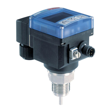
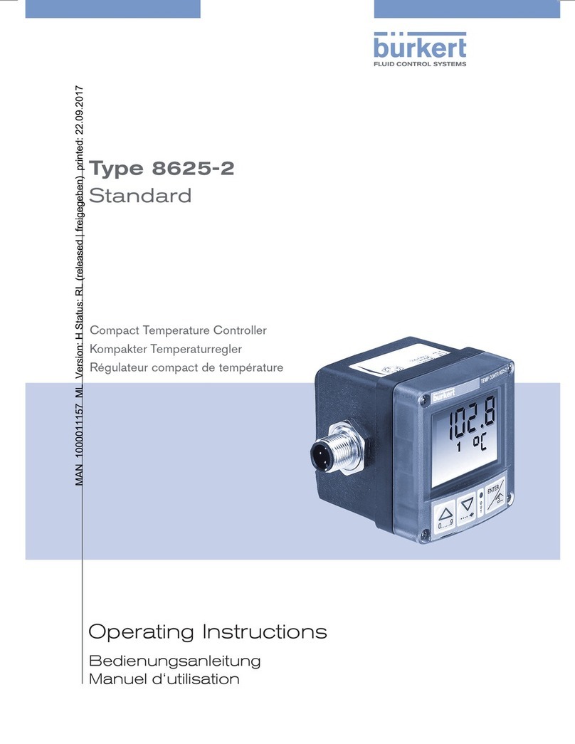
Burkert GENERIC 8400 User manual

Instruction Manual
© Bürkert 2001 Subject to technical change without notice

ENGLISH
ENGLISH
1.1 Utilisation..................................................................................................................................................................................................4
1.2 Precautionsatinstallationandcommissioning.........................................................................................................5
1.3 Conformitytostandards..............................................................................................................................................................5
2.1 Design.........................................................................................................................................................................................................6
2.2 Measuringprinciple.........................................................................................................................................................................6
2.3 Availableversion.................................................................................................................................................................................7
2.4 Accessories............................................................................................................................................................................................7
4.1 Generalrecommendations....................................................................................................................................................10
4.2 Mounting...............................................................................................................................................................................................10
4.3 Electricalconnection..................................................................................................................................................................12
4.3.1 Cableplugs.......................................................................................................................................................................... 14
4.3.2 Wiring.......................................................................................................................................................................................14

ENGLISH
ENGLISH
5.1 Generalrecommendations....................................................................................................................................................16
5.2 Functionalities.................................................................................................................................................................................. 16
5.3 Programmingkeys....................................................................................................................................................................... 17
5.4 DefaultConfiguration.................................................................................................................................................................17
5.5 NormalMode.................................................................................................................................................................................... 18
5.6 Possibleswitchingmodes...................................................................................................................................................... 19
5.7 CalibrationMode............................................................................................................................................................................ 20
5.8 SimulationMode............................................................................................................................................................................ 23
6.1 Cleaning................................................................................................................................................................................................ 24
6.2 Errormessages...............................................................................................................................................................................24
Descriptionofthecontrollerlabel................................................................................................................................................. 26

ENGLISH
ENGLISH
The 8400 controller has been designed to measure the temperature of a
liquid or a gas.
There will be no manufacturer warranty for damages caused by unexpect-
ed handling or wrong usage of the device. The warranty on the device
becomes invalid if any modification or change is made on the device.

ENGLISH
ENGLISH
- When the device is powered and the cover is open, protection against
electric shocks is not ensured.
- To clean the device, only use chemically compatible products.
- Always protect the device from electromagnetic perturbations, ultravio-
let radiations and, when installed outside, from the effects of climatic
conditions.
EMC: EN 50 081-1, 50 082-2
Security: EN 61 010-1
Vibration: EN 60068-2-6
Shock: EN 60068-2-27

ENGLISH
ENGLISH
The temperature controller 8400 is an electronic module which has to
be inserted into an holder previously mounted on a wall. It may switch a
solenoid valve, activate an alarm or establish a control loop.
It must be associated to a remote 3-wire Pt100 temperature sensor.
The switching point can be adjusted by means of the three keys located
under the display.
The electrical connection is carried out via a steerable 5-pin M12 male
connector and a 4-pin M12 female connector.
The controller 8400 measures the resistance of the remote Pt100 sen-
sor.
Wall-mounted holder

ENGLISH
ENGLISH
12-30 VDC Measuring signal and
compensation Transistor NPN and PNP 5-pin M12 male fixed connector and 4-pin M12 female
fixed connector
5-pin M12 female cable plug, to be wired
5-pin M12 female cable plug, moulded on a shielded cable (2 m)
4-pin M12 male cable plug, to be wired
4-pin M12 male cable plug, moulded on a shielded cable (2 m)

ENGLISH
ENGLISH
Measuring range of the
electronic module -40 °C to +125 °C, if the ambient temperature is between 0 and +40 °C
-40 °C to +90 °C, if the ambient temperature is higher than +40 °C
Accuracy ±0.5 °C (0 to 80 °C)
±1.5 °C (outside range 0 to 80 °C)
Repeatability 0.4%
Measuring element remote 3-wire Pt100 temperature sensor
Protection rating IP 65, cable plugs beeing plugged-in and tightened
Installation class
(overvoltage class) 2
Power supply 12-30 VDC
Current consumption max. 750 mA + consumption of the load, if output PNP is connected
max. 80 mA + consumption of the load, if the PNP output is not connected
Protection against
polarity reversal yes
Transistor output NPN and PNP, open collector, max. 700 mA, NPN output: 0,2-30 VDC and
PNP output: controller voltage supply
Protection against
short-circuits yes for the transistor output

ENGLISH
ENGLISH
Recommended cable type
Power supply shielded, section between 0,14 and 0,5 mm2
Remote Pt100 max. distance: 10 m, max. section 0,5 mm2; wire resistance < 2 Ω at ambient temperature
Wall-mounted controller 5-pin M12 female cable plug and 4-pin M12 male cable plug (not supplied)
Housing polycarbonate, fiber glass reinforced
Front plate polyester
Wall-mounted armature PVC
Ambient temperature 0 to +60 °C (0 to +40 °C if fluid temperature may exceed +90 °C)
Relative humidity < 80%, non condensated
88
22
62
12
54

ENGLISH
ENGLISH
Always check the chemical compatibility of the materials the controller is
made of with the products it may be in contact with, for instance: alco-
hols, strong or concentrated acids, aldehydes, bases, esters, aliphatics,
aromatics, ketones, aromatics or halogenated hydrocarbons, oxidizing
agents and chlorinated products. For more information, please contact
your Bürkert sales office.
1. Select the location of the holder on a wall, then drill 4 holes by
respecting the hole-to-hole distances indicated on the opposite
schematic and mount the holder using 4 screws.
40 mm
30,5 mm
12 mm
3 mm
ø 7,4 mm
ø 4,7 mm

ENGLISH
ENGLISH
2. Insert the controller in the holder as shown in the figure below.
3
1
2
3. fasten screw [3].

ENGLISH
ENGLISH
Always ensure the power supply is switched off before working on the
device. All the cable plugs must be plugged out.
Use:
- a shielded cable with an operating temperature > +80 °C.
- a high quality voltage supply (filtered and regulated).
8400
NPN
PNP
+
-
0 V
V+
Pt100
GND
1A
Load
NPN output
PNP output
Measure
Measure compen-
sation
Receiver + power supply
(PLC for ex.)
Load

ENGLISH
ENGLISH
Receiver +
power supply
(PLC for ex.)
Remote 3-wire
Pt100 sensor

ENGLISH
ENGLISH
1 2
34
2 1
Measure
Not connected
1 brown
2 white
3 blue
4 black
GND
Compensation
- Loosen threaded ring [1]
- Remove part [2] from the connector.
- Wire according to pin assignment (see 4.3.2)
1 2

ENGLISH
ENGLISH
4
5
3
12
0 VDC
V+
(12-30 VDC)
PNP transistor output
1 brown
2 white
3 blue
4 black
5 grey
The controller is fitted with a steerable 5-pin M12 fixed
connector:
Unfasten counternut. Turn the fixed connector to the
right position, but by max. 360° to avoid twisting of the
cables inside the housing. Fasten counternut using the
appropriate tool while maintening the fixed connector
in the right position.
NPN transistor output
(*) Functional earth
When the cable plugs are not correctly plugged-in and tightened, there is
a risk to electrocute yourself.
Always check all the cable plugs before powering the device to ensure
the good operating of the device.

ENGLISH
ENGLISH
Keep in mind that the process may be influenced by all the parameter
settings you make. Fill-in the table on page 22 with your settings of the
controller.
The device has three operating modes :
Display of the measured temperature and the programmed switching
thresholds. From the Normal mode, you can access the Calibration and
Simulation modes.
Access to the programming of all the parameters (unit, output, filter,
bargraph, temperature adjustment). From the Calibration Mode, you can
go back to the Normal Mode.
Entering a theoretical flow rate value to test the configuration pro-
grammed in the Calibration Mode. From the Simulation Mode, you can go
back to the Normal Mode.

ENGLISH
ENGLISH
At the first powering up, the configuration of the wall-mounted controller 8400 is as follows:
T° unit: °C
Output: hysteresis, inverted
OLO: 130 °C
OHI: 130 °C
DEL: 0 s
filtre: 2
BGLO: 0 °C
BGHI: 100 °C
T° adjustment: 000.0
Extension board: no (feature not used)
To display the measured value and the configuration (8
characters: 4 numeric et 4 alphanumeric charact.)
Modifies the displayed value (0…9) ;
To go to the previous function.
To select the character;
To go to the next function.
To validate a function;
To validate the entered data.
To indicate the status of the
switching output (red LED)

ENGLISH
ENGLISH
+
> 5 s
+
> 5 s
3
1
+ +
> 5 s
ENTER
ENTER
0......9
0......9
ENTER
0......9
2
010.9
°C
050.5
O HI
015.5
O LO
the measured
temperature.
Note: When the units flash,
the min. or max. value of the
authorized range has been
exceeded.
the high threshold
value (O HI).
the low threshold
value (O LO).
to the previous
feature.
the next feature.

ENGLISH
ENGLISH
2 s
OHI
OLO
2 s 2 s
DEL = 0 s
DEL = 2 s
DEL = 0 s
DEL = 2 s OFF
ON
OFF
ON
OFF
ON
OFF
ON
OFF
ON
OFF
ON
OFF
ON
OFF
ON
The change of state occurs when a threshold is
detected (increasing temperature: high thresh-
old (OHI) to be detected, decreasing tempera-
ture: low threshold (OLO) to be detected).
The change of state occurs when any
threshold is detected.
T°
Time
Hysteresis Mode
Window Mode
Not inverted
Not inverted
Inverted
Inverted
Not inverted
Not inverted
Inverted
Inverted
Contact Contact
T° T°
Not inverted
Not inverted
Inverted
InvertedContact Contact
T° T°
ON
OFF OLO OHI
ON
OFF
OLO OHI
ON
OFF OLO OHI
ON
OFF OLO OHI

ENGLISH
ENGLISH
100.0
050.5
0 HI
OUT
END
OHI>
OLO
0......9
ENTER
1
BRGR
9
FILT
030.0
BG LO
ENTER
BG HI
0......9
°C
°F
mode
mode
ENTER
0......9
2
015.0
0 LO
NO
INV
92
DEL
YES
INV
ENTER
ENTER
ENTER
ENTER
ENTER
0......9
0......9
ENTER
ENTER
0......9 0......9
0......9
ENTERENTER ENTER
0......9
ENTER
ENTER ENTER
ENTER
FILT
T° 000.5
°C
ENTER
0......9
ENTER
NO
EXT
ENTER ENTER
EXT
0......9
*
*
*
*
*
UNIT
the unit of the
temperature (°C or °F).
- the switching mode of the
output (Hysteresis or
Window, see p. 19)
- the low (O LO) and high
(O HI) switching thresholds
- whether the switching mode
is inverted or not (INV, see
p. 19)
- the delay before switching
(DEL, in seconds)
the filtering level
of the displayed T° (FILT); «0»
means "all the temperature
variations are displayed", «9»
smoothes the displayed tem-
perature values at the most.
to the previous
feature.
the next feature.
yes
no
* To enter a negative value, select the character at the left hand side of the
display and press
0......9
until the minus sign appears.
Other manuals for GENERIC 8400
5
This manual suits for next models
5
Table of contents
Languages:
Other Burkert Temperature Controllers manuals
Popular Temperature Controllers manuals by other brands

Lubing
Lubing Top Climate System Assembly instructions and operator's manual

Vaillant
Vaillant VRT 50 Operating and installation instructions

Tzone
Tzone TZ-Tag06 user manual

Bryant
Bryant SYSTXBBECW01-A installation instructions

Tech Controllers
Tech Controllers EU-292n v2 user manual

VOLTCRAFT
VOLTCRAFT ECB-1000P operating instructions