Burkhard Reuter RLA4 User manual

Specifications
and Operator's Manual of Antenna
RLA4
Edition: 1.5
Created: 11.01.2019
Konstruktion & Musterbau Burkhard Reuter Ziegelstraße 54 06862 Dessau-Roßlau

Specifications
Single loop dimensions: 360 mm x 360 mm
Amplifier dimensions (W x H x D): 85 mm x 50 mm x 127 mm
Frequency range: 50 kHz … 71 MHz
Average noise level (without loops): <= -139 dBm/Hz (at 10 MHz)
IP3: >= +30 dBm (2x -6 dBm measuring tone at 10 MHz)
IP2: >= +78 dBm (10.0 MHz + 10.2 MHz -6 dBm test tone,
0.2 MHz measured difference tone)
Output voltage: >= 1.1 Veff, 1 dB compression
Supply via DC jack: +12.0 V ±0.1 V, maximum +14.4 V!
Supply via HF cable: +7.0 V … +13.8 V, maximum +14.4 V!
Power supply: max. 100 mA
Power supply socket: DC-connector pin 2.5 mm (0,1”)
HF output: BNC 50 Ohm
Weight: <= 1 kg (depending on loop material)
Environmental conditions: 0 ... +50 °C ambient temperature, <=90 % rel. humidity
non-condensing, indoor application, limited outdoor application
Compliance: CE according to DIN EN 55013, EN 55020, EN 60065
RoHS / WEEE directive, ear reg. nr. 27676700
Specifications are subject to change!
EDITION DATE NAME K & M Burkhard Reuter Page 2of 9
1.5 8/19/19 B. Reuter RLA4

Safety information
Please always observe the following safety instructions!
Never connect the device to any other voltage than indicated in the specifications. Under no
circumstances should the the device come into contact with the mains voltage of 110 / 230 V ~!
The device is intended for indoor use. Do not expose it to moisture. If moisture (e.g. spilled drinks)
has accidentally come into contact or even got into the device, immediately take it out of operation
(remove power supply) and send it back to the supplier for verification!
If you use the device outdoors (observe temperature and humidity restrictions!), please observe
the lightning protection regulations for the outdoor operation of electrotechnical systems! In case
of risk of lightning hazard, immediately take the device out of operation and disconnect it safely
from other devices (remove RF connection)!
Observe the permitted temperature range for starting up the device! Do not switch the device on or
off again if this range is exceeded or fallen below!
Always ensure a safe installation on a level, even and firm surface of adequate load-bearing
capacity! Always transport the device either in solid cardboard or wooden boxes (e.g. the delivery
packaging), or transport it by firmly gripping the amplifier housing! The device may cause injury in
the event of a fall due to its own weight!
Never expose the device to mechanical stress such as impact, pressure, vibration or shock
beyond what exceeds the domestic use of electronic equipment! Never carry or fasten the device
to the antenna element.
If you notice any damage to the device, immediately take it out of operation (remove power
supply)! If necessary, return it to the supplier for repair.
If you wish to dispose the device due to damage or because you do not use it anymore, return it to
the supplier or to your local waste collection center. Never dispose the device in any other way, for
example, with your household waste!
Use only soft, lint-free and dry cloths for cleaning the device! In case of persistent soiling, never
use solvents! At most, a slight moistening of the cleaning rag with distilled water is appropriate!
Make sure that moisture never penetrates into the device!
EDITION DATE NAME K & M Burkhard Reuter Page 3of 9
1.5 8/19/19 B. Reuter RLA4

Operator's Manual
The RLA4 is a small loop receiving antenna for indoor or portable outdoor use. It operates broadband as
an untuned active antenna with integrated amplifier. The antenna can be powered via the RF cable or a
DC socket directly on the amplifier. The receiver element consists of 2 etched copper loops on FR4 board
material for symmetrical feed of two differential current amplifiers with very low impedance input. The use
of the latest components within the two amplifier branches guarantees low intrinsic noise values and high
intermodulation resistance. The two receiving loops are arranged at an angle of 90° to each other. They
can be switched by switching the respective amplifier on or off.
The RLA4 also provides fine-step control of the amplifier to achieve electronic rotation of the receiving
direction. In versions 4A to 4C, the amplifier can be switched to high-impedance input asymmetrical to
ground. The entire loop design then no longer operates as a loop ("magnetic") antenna but as a "whip"
antenna for omnidirectional reception of the electric field component.
The amplifier operates within an anodized aluminum profile housing. The connection to the RX is made via
a BNC socket. A DC socket is available for local supply (for usual plugs of universal power supply units).
The positive pole lies on the pin (2.5 mm). Power can also be supplied via the RF cable (remote supply).
To feed the DC voltage into the cable, a bias tee is required (not included in delivery) or a receiver with the
ability to feed preamplifiers directly from the receiver input.
Up to version 4C, the antenna is switched on by a lighted toggle switch and switched over in receiving
mode (magnetic "loop" / electrical "whip").
The RLA4A-C's connectors and switches
When operating the RLA4 via the normal circuit as a loop, the loop is active from the front right (via jack
"RX") to the rear left. Its main reception direction lies in this direction (in the loop plane, corresponds to 0°).
To change the receiving direction, the antenna must be rotated. This can be done mechanically by turning
the housing together with the loop construction, or electronically by using the control unit for the RLA4 (see
separate description). In loop mode, the receiving loops are grounded by the rod in the middle.
As a result, and due to the generally low noise sensitivity of loop antennas, a good suppression of local
interferences (emissions from PC, TV, switching power supplies, cabling, etc.) is achieved. In addition, the
performance of the antenna is relatively independent of the operating site. It requires neither a particularly
increased position, nor special grounding wires or the like (however, overvoltage protection must be
observed!).
When operated as a whip, the entire construction including the center rod is electrically separated from the
chassis ground ("ground-plane"). In addition, due to the now high-impedance circuit of the amplifier
(almost) no current flows in the loops. Instead, the potential difference of the loop construction is
measured against earth. It thus acts as a probe for the electric field component of the received EM field.
EDITION DATE NAME K & M Burkhard Reuter Page 4of 9
1.5 8/19/19 B. Reuter RLA4

This results in an omnidirectional reception without pronounced main receiving direction or suppression in
one direction. In addition, the reception power is highly dependent on the installation of the antenna. A high
installation location as well as a large distance to conductive and / or noise emitting parts should be
chosen. In whip mode, the antenna easily picks up local noise. It is also more sensitive to overvoltages
(e.g. static discharge when touching the receiving loops or nearby transmitters). Always touch the housing
or other grounded conductive parts in the vicinity before touching the loop construction!
The antenna is not protected against direct lightning and must not be operated in lightning-prone
environments!
Caution! The switch consists of only a small operating lever made of plastic and may only be used
cautiously! Do not use forces greater than necessary for direct switching!
In operation, the lever lights red in loop mode and green in whip mode. When switched off, there is no
display and the power consumption is completely zero.
The antenna elements (loops) are easy to disassemble. Each loop consists of 2 sections assembled to the
amplifier with one screw and two screws to the common mounting and grounding point. After removing the
screws with a suitable screwdriver, the element is removable. The center rod can be turned out after
loosening the lock nut on the housing. When the receiving elements are removed , the antenna can be
packaged and transported to save space.
Caution! During assembly work on the antenna, torque must never be transferred to the 5 connection
bolts of the amplifier! This can damage the inner PCB! Always keep the bolts firmly in its correct position,
e.g. with a suitable nut key!
Versions for loop constructions
The RLA4 is available in 3 basic versions (extended versions see below):
- RLA4A: Normal version with 2-layer black coated loop material.
- RLA4B: "Blue version" with 4-layer blue coated loop material.
- RLA4C: Special version with loops made of flexible stainless steel.
In version B, the outer layers of the loops are connected to ground and only the inner layers carry power to
the amplifiers. This results in an additional shielding of the receiving loops against interference voltages.
Depending on the environment and on the reception frequency an increased attenuation can be achieved.
Version C includes spring steel loops. They are attached by knurled nuts, which allows a quick
disassembly and assembly. This allows the antenna to be transported space-saving. In addition, the loop
straps are very robust and rustproof, so that the RLA4C is well suited for portable use (housing is not
completely waterproof). The stainless steel bands offer up to approx. 10 MHz the same receiving power as
the copper loops of the RLA4A and B, only above the performance drops slightly.
In whip operation, the material of the loops is irrelevant. All versions give the same reception performance.
Remote supply / direction control
The previous description refers to the supply of the antenna directly to the housing with 12 V DC. The
RLA4 can also be supplied with operating voltage via the RF cable (remote supply). The local supply via
the DC socket should then be removed. The switch is no longer active and doesn't light up, even if the
antenna is receiving power via the remote power supply!
Caution! The antenna should always be supplied via a well-stabilized, interference-free power supply
("analogue" or "linearly controlled"). This is especially true for the local supply via the DC socket.
For remote supply, various methods for controlling the antenna are available (applies to versions A to C):
•Supply with > 8 V (observe permissible maximum!): The RLA4 operates in loop mode.
•Supply with <= 8V (observe the required minimum!): The RLA4 operates in whip mode.
•Supply with 6 V and modulation of an RS-232 signal with active level of min. 7 V and
maximum 8 V: Control of the RLA4 in all available operating modes.
EDITION DATE NAME K & M Burkhard Reuter Page 5of 9
1.5 8/19/19 B. Reuter RLA4

For complete control of all available modes, the remote supply voltage must be modulated with a logically
negative RS-232 signal (start bit = increased supply voltage, stop bits = supply voltage). The data format is
125 Baud 8N2 (8 data bits, no parity bit, 2 stop bits). Only one data word (8 bits = 1 byte) is transmitted.
The control of the antenna depends on the received byte as follows:
•Value 0 to 126: Loop operation with setting the receiving direction from 0° to 180° in 127 steps.
•Value 127: Whip operation.
•Value 128 to 255: No reaction (reserved for future developments).
After switching on the remote power supply with a voltage of 6 V (up to a maximum of approx. 8 V), the
antenna is initially in whip mode. As soon as a data byte has been successfully received, the antenna
switches to the desired operating mode. The direction switching in loop mode is not possible linearly to the
control word. The main receiving directions of the two loops are largely preferred, as are the intermediate
stages (each 45° to the loops if both loops are equally active). In these directions, the antenna also
reaches its highest gain and works with the least distortion.
The effective rotation of the receiving direction between the 45° main directions is temperature and voltage
dependent. The corresponding control bytes result in a more or less large offset to this or more or less fast
panning between the main directions. In any case, it is possible to set clearly defined directions of
reception between the 45° main directions by varying the control bytes.
The purpose of such a fine-grained directional adjustment is not to detect a station to be received with a
maximum level. The "eight" characteristic of the loops with a very wide reception lobe allows optimal
reception with barely perceptible attenuation outside the exact main reception direction, even if the
antenna is not precisely aligned. Rather, the purpose lies in the most accurate possible positioning of the
zero point (minimum reception) with high suppression in this direction. The zero point has a sharp
directional characteristic and must therefore be set accurately. In most cases, there is a matching control
byte for the RLA4 for exact positioning of the zero point in the desired direction. However, this is different
for varying operating conditions (voltage, temperature).
The optional control unit for the RLA4 allows the generation of all possible bytes via a potentiometer. Thus,
by manually "tuning", the appropriate byte can be found by observing the reception on the receiver.
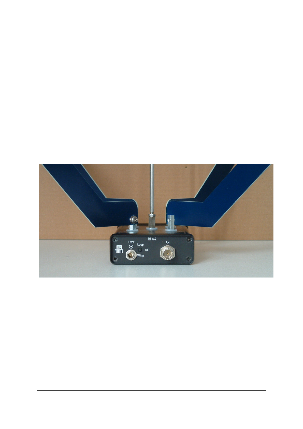
The control bytes 0 and 126 are equivalent. They switch the 1st loop (see switch on the antenna for loop
operation) either in phase, or directly opposite (180°) to the amplifier. Since the loop characteristic is
bidirectional, this corresponds exactly to the same reception conditions.
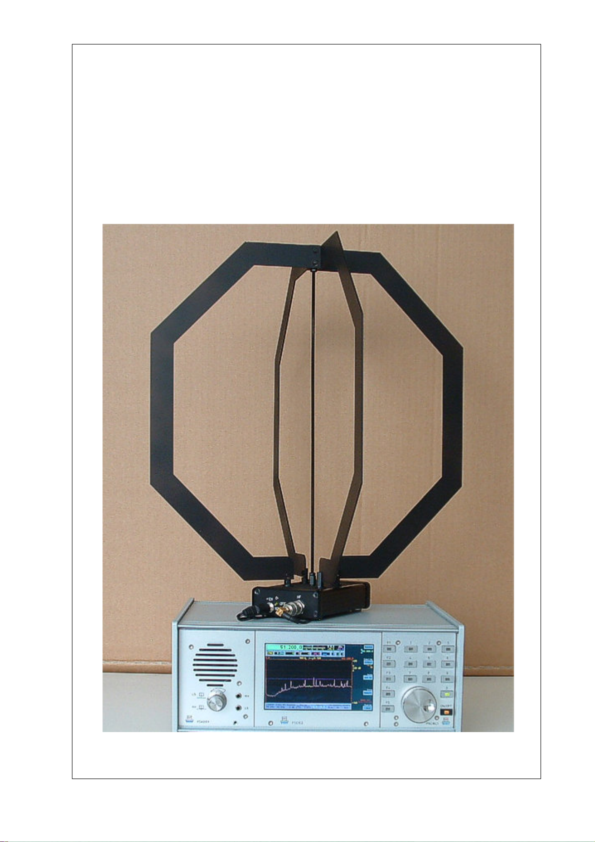
Tips for an ideal RLA4 operation
- The antenna is highly sensitive in spite of its small design and delivers high reception levels in
broadband. Sensitive receivers can be overmodulated. In such a case, you should place an attenuator or
better a preselector between the antenna and the RX.
- Even if you are tempted to position the antenna near the RX: Check its noise emissions and those of
other nearby devices, and place the antenna at a distance from it. Especially personal computers and their
peripherals (monitor, printer / scanner, SDR, network cables ...) as well as televisions and the like often
generate very high levels of interference.
- Prefer loop operation as often as possible. The whip operation usually only offers advantages at low
frequencies except when omnidirectional reception is desired.
Expansion of the direction control
In certain cases, the direction control's 127 steps allow only a relatively coarse setting (about 3° per step).
This is often too inaccurate to adjust the antenna to high suppression of a certain signal (positioning of the
receiving zero). Especially in the lower frequency range, the RLA4 reaches a suppression value of 50 dB
and more at exactly the zero point. The zero is very narrow. Even a turn of 1° reduces the attenuation.
Therefore, the direction control's resolution has been increased for the following antenna types:
- RLA4A from S/N 0095
- RLA4B from S/N 0097
- RLA4C
- Individual boards RLA4 from version F2
EDITION DATE NAME K & M Burkhard Reuter Page 6of 9
1.5 8/19/19 B. Reuter RLA4

The number of steps for a 180° rotation now amounts to 232, with step 232 enabling the "Whip" mode.
Steps 0 - 231 set the loop operation from 0° to 179°. Thus, a rotational accuracy of less than 1° can be
achieved in the "less sensitive" areas around the 45° main receiving directions (planes of the loops and
45° each between the loop planes). In the "more sensitive" areas between the main reception directions,
the resolution is even better than 2°.
In order to be able to set the increased number of steps accurately, the associated control unit RSW2 has
been updated (see RSW2 description). Now, no potentiometer with a fixed rotation angle of approx. 270°
is used, but a pulse rotary encoder with an "infinite" rotation angle. For each pulse, exactly one step is
made forward or backward. This ensures that every possible step can be set accurately. Turning to the left
or to the right of "Omnidirectional" is not limited, but has no effect.
To increase the transmission reliability and expansion of control options (additional switching in antennas,
simultaneous control of multiple or combination antennas, etc.), the control unit now sends a 9-bit data
word with one parity bit. The corresponding setting of serial transmitters ("UART", "COM port", "RS-
232" ...) is now "9E2": 9 data bits, 1 parity bit with even parity, 2 stop bits. The data rate is still 125 baud.
Versions RLA4D, E and F
The versions D to F match the previous versions A to C:
- RLA4D: Normal version with 2-layer black coated loop material.
- RLA4E: "Blue version" with 4-layer blue coated loop material.
- RLA4F: Special version with loops made of flexible stainless steel.
In contrast to the older versions, the newer versions no longer have a circuit for omnidirectional reception
in "whip mode". This operating mode has proven to be barely usable with the usual installation of the
antenna (interior). Due to the omission of the circuits for this operating mode, the versions D - F now
achieve slightly better values for the IM suppression and the inherent noise in loop mode. The version of
the boards for homemade purposes is now called 4G. This board is also installed in the antenna versions
4D – 4F.
Assembly and disassembly
The RLA4 is usually shipped in partially disassembled condition. In this condition, it can be packed and
transported to save space. For mobile use, disassembly for transportation is ideal. Especially the RLA4F
can be assembled very easily and without tools. Proceed as follows:
- Unscrew the knurled nuts from the connecting bolts of the amplifier and the upper side of the threaded
rod (if unscrewed during transport, so as not to lose them).
- Two washers are provided for the bolts on the amplifier. First put one on each of the 4
connecting bolts (with threaded pin).
- Now screw the threaded rod with the large knurled nut down in the middle bolt (with internal thread).
Tighten the knurled nut slightly to lock the thread.
- At the top of the threaded rod sits a normal nut. Put a washer on top.
- Place one end of a steel strip on a connecting bolt so that it points away from the amplifier at a 45° angle.
Place the second washer for this bolt on top, screw on the knurled nut and tighten slightly.
- Bend the other side of the strip over the amplifier and secure it to the opposite pin with washer
and knurled nut. Caution! Do not bend the strip sharply, just bend it evenly! Attention! The strips are
very thin and can cause cutting when there is heavy pressure on their edges (risk of injury, danger of
damaging other things)!
- Place the middle of the strip on top of the threaded rod.
- Attach the 2nd strip just as described above. Both strips should form an angle of 90° to each other and
each 45° to the amplifier housing.
- Place the second washer on top of the threaded rod and screw on the knurled nut.
- Carefully tighten all knurled nuts hand-tight. Caution! Do not use any tools (like pliers)!
The connection bolts of the amplifier must not be twisted!
The following images illustrate the position and mounting of the individual components.
EDITION DATE NAME K & M Burkhard Reuter Page 7of 9
1.5 8/19/19 B. Reuter RLA4

Connection bolt of the amplifier with an installed steel strip
Connection of the steel strips with the threaded rod
The RLA4 versions D and E possess individual elements made of printed circuit board material (FR4)
instead of the stainless steel loops. Each closed loop consists of 2 elements, each of which must be
screwed on using short M4 screws (Torx) and a spring washer. For this purpose, the connecting bolts of
the amplifier have vertical flat surfaces with threaded holes. At the top of the threaded rod 2 mounting
cubes with 4 internal threads each are installed. In total, 3 screws with spring washers are required for
each loop section (one for the connecting bolt, two for the mounting cube of the threaded rod).
The following images illustrate the assembly of the loop elements.
EDITION DATE NAME K & M Burkhard Reuter Page 8of 9
1.5 8/19/19 B. Reuter RLA4

Connection bolt of the amplifier with a screwed-on loop half
The loop elements possess different contact surfaces on each side. On the back a square for installation
of the connecting bolts, in the front a round for contact with the washer. The sides must not be confused,
otherwise the proper function can not be guaranteed.
Installing a loop half to the assembly cubes (2nd screw is still missing)
The threaded rod has a normal nut at its lower end. To counter against the middle bolt of the amplifier, a
suitable open-end wrench is required. Hold the bolt with a second wrench! It is important to ensure that the
mounting cubes are at a 45° angle with their surfaces to the amplifier housing.
The loop elements also have a large contact surface at the top connection and round contact surfaces at
the front. To ensure good contact, the element must rest on the mounting cube with the right side.
Caution! It is absolutely necessary to avoid twisting the bolts on the amplifier! If the flat surfaces of the
connecting bolts deviate significantly from the 45° direction to the housing, then a careful turning to the
correct position with the aid of an open-end wrench can be attempted. If this requires a great deal of effort,
or if the bolt loosens, the amplifier must be dismantled and the internal screwed connections must be re-
fastened.
EDITION DATE NAME K & M Burkhard Reuter Page 9of 9
1.5 8/19/19 B. Reuter RLA4
Table of contents