manuals.online logo
Brands
  1. Home
  2. •
  3. Brands
  4. •
  5. COBHAM
  6. •
  7. Antenna
  8. •
  9. COBHAM SAILOR 800 VSAT Use and care manual

COBHAM SAILOR 800 VSAT Use and care manual

Field
Replacement
Procedure
Following legal entities are trading as / doing
business as Cobham SATCOM
Thrane
and Thrane A/S, Kgs. Lyngby, Denmark
Sea Tel Inc., Concord USA
TracStar Systems
Inc., Orlando, USA
Omnipless Manufacturing (Pty) Limited, Cape Town, RSA
www.cobham.com/satcom
SAILOR 800, 900A & 900B VSAT– Polarization Motor Procedure
Brief Summary:
Troubleshooting document for inspecting and replacing the polarization motor (S-62-134493) on the
SAILOR 800 (7008A), 900A (7009A) and 900B (7009B) VSAT antennas.
Checklist:
Status LEDs
Events List / Error Log. Identify Defective Part
Replace Part
Verify Initialization and Run POST Test
Theory of Operation:
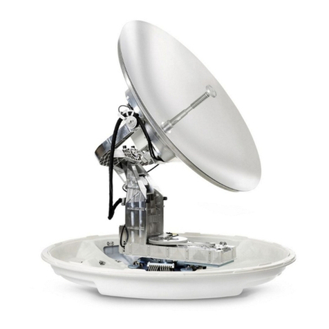
A stepper motor is installed on the rear of the dish of the SAILOR 900 VSAT antenna to rotate the
polarization unit through its 270 degree range of motion.
A zero reference point (magnet) is installed in the drive pulley of the polarization as a reference
position. When the system is energised the stepper motor will drive the polarization unit from one end
stop to the other with the hall effect sensor on the Zero Reference Module (ZRM) reading the
magnetic forces in each direction and taking a mean value as a reference position.
Upon initialization the encoder on the polarization unit will be calibrated based on the axis’s zero
reference position and will increment/decrement the drive steps made by the polarization motor.
When targeting a linear satellite the polarization motor will drive the polarization unit until it reaches
the calculated position, based on the vessels GPS position and the look angle to the satellite. At this
point the encoder will be outputting the desired target value, meaning that the Ortho-Mode
Transducer (OMT) is correctly aligned to the linear receive and transmit signals of the satellite for
maximum signal strength and quality.
As the vessels sails and the GPS position changes small adjustments will need to be made to the angle
of the polarization unit to maintain alignment with the linear satellite signal. This will cause the value
the Pedestal Control Module (PCM) is expecting from the encoder to change, meaning the PCM will
issue the command to drive the polarization motor until the correct feedback from the encoder is
received.
Cobham SATCOM
Global Customer Service dept.
Document no.: 97-139037-C
Revision: C
Date: April 2013
Page 2 of 10
www.cobham.com
/satcom
Spare Part Instruction – SAILOR 800 & 900 Pol Motor
Document No.: 97-139037-C
Revision: C
Troubleshooting - Diagnostic LEDs on the ACU:
The ACU has 3 LEDs: Power, Logon and Fail/Pass.
Verify the status of the unit by referencing the LEDs. If any of the LEDs are not steady green or
flashing green then further diagnostics will need to be undertaken, referencing the below table:
If the Fail/Pass LED is illuminated any colour other than steady green then it means there is an issue
with the system. Log into the ACU using your web browser and refer to the systems event log as
detailed in the following sections of this document.
Page 3 of 10
www.cobham.com
/satcom
Spare Part Instruction – SAILOR 800 & 900 Pol Motor
Document No.: 97-139037-C
Revision: C
Log into the Antenna Control Unit (ACU):
1. Connect a straight through Ethernet cable from the LAN port of your laptop to the LAN port of
the ACU.
2. Open the “Network and Sharing Center” on your laptop and select “Change Adaptor Settings”.
3. Right-Click the LAN adaptor for your laptop and select the “Properties” tab.
Continued…
Page 4 of 10
www.cobham.com
/satcom
Spare Part Instruction – SAILOR 800 & 900 Pol Motor
Document No.: 97-139037-C
Revision: C
4. Double click the “Internet Protocol Version 4 (TCP/IPv4)” Option.
5. The Select the “Use the following IP address” button and enter in an IP address of “192.168.0.2”
and a Subnet Mask of “255.255.255.0”.
6. Now click the OK button on both the “IP Protocol Version 4 (TCP/IP)” window and the “Local
Area Connection Properties” window.
7. Open your web browser and enter the IP address “192.168.0.1”, then press the enter button.
Continued…
Page 5 of 10
www.cobham.com
/satcom
Spare Part Instruction – SAILOR 800 & 900 Pol Motor
Document No.: 97-139037-C
Revision: C
8. You’ll now have access to the systems “DASHBOARD”.
9. The following procedure will tell you how to access the events list and diagnose any errors or
warnings with the system.
Page 6 of 10
www.cobham.com
/satcom
Spare Part Instruction – SAILOR 800 & 900 Pol Motor
Document No.: 97-139037-C
Revision: C
Troubleshooting – Event List:
When an event is registered the web interface shows an event icon “ ” in the icon bar as long as
the event is active, the ACU display also shows active events.
To view the event list with active events click the event icon from the icon bar ( ) at the top of the
web interface or select “HELPDESK” and then “Event list” from the navigation pane on the left of the
user interface.
The Events List page then shows a list of active events and notifications including:
The time and date of the first occurrence (Time UTC)
The event code (ID)
The severity of the event message (Severity)
A description describing the event (Text)
For a more comprehensive diagnosis of the event displayed reference the error and event codes
document, document number: 97-139344-A. Once diagnosed replace the defective component and
run the Power On Self Test (POST) and verify the operation of the system.
*Note: Active events are cleared from the event list when the error is cleared. They are then moved
to the notifications section and are displayed there with the severity, after 24 hours the notifications
are then cleared or after the system is restarted.
Page 7 of 10
www.cobham.com
/satcom
Spare Part Instruction – SAILOR 800 & 900 Pol Motor
Document No.: 97-139037-C
Revision: C
Replacing the Polarization Motor:
Tools needed:
•Torx TX20 Screwdriver
•4mm Allen Key (provided in the radome hatch, part number: S-47-206968-004)
Flat-head Screwdriver
1. Open the service hatch by releasing the two
latches using a Torx TX20 screwdriver (if applicable).
2. Rotate the antenna pedestal so that the arm with
the GPS antenna faces the service hatch.
3. Switch off the power to the antenna using the
service switch, located on the rear of the pedestal.
4. Rotate the antenna dish to 90 degrees of elevation
(facing upwards).
5. Press in and turn the elevation locking pin to the
locked position (if applicable).
6. Remove the connector marked “M” from the PMM.
7. Now disconnect the D-Sub connector from the
PMM using a small flat-head screwdriver.
8. Disconnect the two RF F-connectors from the LNBs
using an 11mm spanner. Mark the LNBs after the
label on the wires: Co-pol (left) and X-pol (right).
9. Disconnect the transmit N-connector.
Page 8 of 10
www.cobham.com
/satcom
Spare Part Instruction – SAILOR 800 & 900 Pol Motor
Document No.: 97-139037-C
Revision: C
10. Remove the four 4mm Allen screws to free the
cable spool attached to the PMM, using the 4mm
Allen key provided in the radome hatch. Let the cable
spool hang freely, retain the hardware for future use.
You can now access the polarization motor.
11. Disconnect the power connector of the
polarisation motor.
12. Remove the four 4mm Allen screws that hold the
motor, retain the hardware for future use.
13. Remove the defective polarisation motor.
14. To insert a new polarisation motor follow the
instructions above in reverse order.
15. Once the replacement polarization motor has
been installed verify that the antenna passes the
Power On Self Test (POST) as per the following
procedure.
Page 9 of 10
www.cobham.com
/satcom
Spare Part Instruction – SAILOR 800 & 900 Pol Motor
Document No.: 97-139037-C
Revision: C
Troubleshooting - Verify the Initialization of the Pedestal:
After replacing the defective component re-initialize the pedestal and verify its operation. First switch
off the power to the antenna using the service switch, located on the rear of the pedestal:
Then restart the pedestal by pressing and holding the and arrows on the ACU together:
Now view the pedestal through the service hatch and switch on the service switch located on the rear
of the pedestal. Now verify the Initialization process is as follows:
1. The elevation axis will drive from end-stop to end-stop and then to its zero reference point, with
the reflector at 45 degrees.
2. The cross-elevation then drives from end-stop to end-stop and then to its zero reference point,
level with the horizon.
3. Then the azimuth axis drives one direction and then back on itself before settling at its zero
reference point, with the antenna facing away from the service hatch.
4. And finally the polarization unit then drives from end-stop to end-stop (270 degrees) and then
back to its zero reference point, at which point the polarization motor module will be at the
highest point of the polarization unit with the LNB coax cables pointing left.
*Note: Any errors during the Power On Self Test (POST) will make the system go to safe mode,
dropping the ADU power from 48VDC to 20VDC and making the DC-Motor Drive Modules (DDM)
status LEDs illuminate red.
A minor issue with the POST may enable the system to operate, with the Antenna Control Unit (ACU)
displaying a warning. If the Pass/Fail LED is illuminated on the ACU, refer to the error log for further
information.
5. The system will then go into ‘ready mode’, expecting to get data from the satellite modem.
6. The satellite data is then sent from modem and will be displayed on the systems dashboard.
7. The Above Deck Unit (ADU) then goes from pointing the antenna to then acquiring the signal,
and finally into tracking mode.
8. Verify the system completed the initialization process correctly and that no errors were flagged
by the POST.
Page 10 of 10
www.cobham.com
/satcom
Spare Part Instruction – SAILOR 800 & 900 Pol Motor
Document No.: 97-139037-C
Revision: C
Troubleshooting - Self Test:
You can run a self test on the ACU and ADU of the antenna system.
1. From the “HELPDESK” page, click the “Self test” option.
2. The system will now run the Self test.
3. Ensure the test is completed with no errors.
4. If any errors are displayed refer to the “ACU Error Messages” section of this document for further
information.

Other manuals for SAILOR 800 VSAT

1

This manual suits for next models

2

Other COBHAM Antenna manuals

COBHAM Sailor 900 VSAT User manual

COBHAM

COBHAM Sailor 900 VSAT User manual

COBHAM SAILOR 600 VSAT Ka User manual

COBHAM

COBHAM SAILOR 600 VSAT Ka User manual

COBHAM Sailor 500 FleetBroadband User manual

COBHAM

COBHAM Sailor 500 FleetBroadband User manual

COBHAM Sea Tel Tracker 6000 User manual

COBHAM

COBHAM Sea Tel Tracker 6000 User manual

COBHAM Sea Tel 2400 User manual

COBHAM

COBHAM Sea Tel 2400 User manual

COBHAM SAILOR 6120 User manual

COBHAM

COBHAM SAILOR 6120 User manual

COBHAM Sea Tel User manual

COBHAM

COBHAM Sea Tel User manual

COBHAM SAILOR 100 GX User manual

COBHAM

COBHAM SAILOR 100 GX User manual

COBHAM SAILOR 6120 User manual

COBHAM

COBHAM SAILOR 6120 User manual

COBHAM SAILOR 600 VSAT Ka User manual

COBHAM

COBHAM SAILOR 600 VSAT Ka User manual
COBHAM EXPLORER 5075GX User manual

COBHAM

COBHAM EXPLORER 5075GX User manual

COBHAM Sea Tel 4010W-33 User manual

COBHAM

COBHAM Sea Tel 4010W-33 User manual
COBHAM Sea Tel 4010W-17 User manual

COBHAM

COBHAM Sea Tel 4010W-17 User manual

COBHAM Sea Tel User manual

COBHAM

COBHAM Sea Tel User manual

COBHAM SAILOR 900 User manual

COBHAM

COBHAM SAILOR 900 User manual

COBHAM SAILOR 60 GX-R2 4.5 W User manual

COBHAM

COBHAM SAILOR 60 GX-R2 4.5 W User manual

COBHAM SAILOR XTR GX-R2 User manual

COBHAM

COBHAM SAILOR XTR GX-R2 User manual

COBHAM Sailor 900 VSAT User manual

COBHAM

COBHAM Sailor 900 VSAT User manual

COBHAM Sea Tel User manual

COBHAM

COBHAM Sea Tel User manual

COBHAM SAILOR 1000 XTR Ku 8W Use and care manual
COBHAM

COBHAM SAILOR 1000 XTR Ku 8W Use and care manual

COBHAM EXPLORER 5075GX User manual

COBHAM

COBHAM EXPLORER 5075GX User manual

COBHAM EXPLORER 7100GX User manual

COBHAM

COBHAM EXPLORER 7100GX User manual

COBHAM EXPLORER 6075LX Guide

COBHAM

COBHAM EXPLORER 6075LX Guide

COBHAM Explorer 710 User manual

COBHAM

COBHAM Explorer 710 User manual
Popular Antenna manuals by other brands

Cisco 2.4-GHz Swivel-Mount Dipole Antenna... Specifications

Cisco

Cisco 2.4-GHz Swivel-Mount Dipole Antenna... Specifications

Esco ETS-Lindgren 3303 manual

Esco

Esco ETS-Lindgren 3303 manual

RCA ANT711 instruction manual

RCA

RCA ANT711 instruction manual

RCA VH226F user manual

RCA

RCA VH226F user manual

MFJ MFJ-1775 instruction manual

MFJ

MFJ MFJ-1775 instruction manual

TDK VLA-2001 datasheet

TDK

TDK VLA-2001 datasheet

DX Engineering DXE-MBVE-3 manual

DX Engineering

DX Engineering DXE-MBVE-3 manual

DX Engineering DXE-MBVE-5A quick start guide

DX Engineering

DX Engineering DXE-MBVE-5A quick start guide

Wilson Electronics 301143 installation guide

Wilson Electronics

Wilson Electronics 301143 installation guide

Antsig AP537 installation instructions

Antsig

Antsig AP537 installation instructions

Chameleon Antenna CHA F-LOOP 2.0 Operator's manual

Chameleon Antenna

Chameleon Antenna CHA F-LOOP 2.0 Operator's manual

Televes INNOVA BOSS MIX manual

Televes

Televes INNOVA BOSS MIX manual

CUSHCRAFT 22XB Assembly and installation instructions

CUSHCRAFT

CUSHCRAFT 22XB Assembly and installation instructions

Wilson Electronics 301111 installation guide

Wilson Electronics

Wilson Electronics 301111 installation guide

SCHNERZINGER NEW INNOVATOR manual

SCHNERZINGER

SCHNERZINGER NEW INNOVATOR manual

Oricom ANU1100 user guide

Oricom

Oricom ANU1100 user guide

Maxview GAZELLE Easy to fit instructions

Maxview

Maxview GAZELLE Easy to fit instructions

WiMo ULTRABEAM troubleshooting guide

WiMo

WiMo ULTRABEAM troubleshooting guide

manuals.online logo
manuals.online logoBrands
  • About & Mission
  • Contact us
  • Privacy Policy
  • Terms and Conditions

Copyright 2025 Manuals.Online. All Rights Reserved.