manuals.online logo
Brands
  1. Home
  2. •
  3. Brands
  4. •
  5. Burley
  6. •
  7. Stove
  8. •
  9. Burley Icarus 5 Manual

Burley Icarus 5 Manual

Issue 1 November 2019
Installation Instructions
& User Manual
Icarus 5
READ ALL THE INSTRUCTIONS AND ENSURE YOU FULLY
UNDERSTAND THEM BEFORE USING THE STOVE
Conforming to BSEN SIA 13240 2CO1 +A2
ECO Ready lDEFRA approved lA Rated
THESE INSTRUCTIONS MUST BE LEFT WITH THE USER
FOR FUTURE REFERENCE
2
The stove is to be operated in accordance with these operating
instructions and with wood or wood-based fire logs only. It is
approved for intermittent operation within smoke control areas.
DO NOT CARRY OUT ANY WORK OR MAINTAINANACE ON THE STOVE
WHEN IT IS BURNING OR WHEN IT IS STILL HOT
GUARANTEE CONDITIONS
The 3 year Guarantee applies to the main steel body of the stove and
does not include glass, fire rope or fire stone linings, which are
consumables.
The stove must be fitted by a registered HETAS engineer and a
certificate must be available.
Any evidence of poor operation or of using incorrect fuels may
invalidate the guarantee.
Evidence of purchase from an approved supplier will be needed. The
guarantee covers parts only, labour costs are not included.
PLEASE CAREFULLY CHECK YOUR STOVE FOR DAMAGE
OR DEFECTS PRIOR TO FITTING.
WE CAN NOT EXCHANGE DAMAGED OR FAULTY
STOVES ONCE THEY HAVE BEEN FITTED.
AS WITH ALL STOVES, ALWAYS FIT A
SECTION J COMPLIANT CARBON MONOXIDE
DETECTOR IN THE ROOM.
3
Stove Specifications – Output and Efficiency
Maximum Efficiency 78.3%
Average Efficiency 77.7%
Nominal KW output: 5 KW
Wood Logs Results, 40 minute refuels
Parameter
Mean
Total efficiency
77.7%
Nominal heat
output
5.0kW
Mean CO
emission
(at 13% O2)
0.09%
Mean flue gas
temperature
272°C
Flue gas mass
flow
5.0g/s
Mean CxHy
emission (at
13% O2)
57mg/m³
Mean NOx
emission
(at 13% O2)
111mg/m³
DIN plus
particulates
(at 13% O2)
9mg/m³
All efficiencies in table are Net values
All above figures using wood at 14% moisture content (these figures
can vary if the moisture content is higher)
4
Clearances to Combustibles
300mm above, 250mm behind, 300mm to the sides.
Hearths
The stove requires a 12mm depth of non-combustible material placed
on a floor which can support a minimum of 91kg. Minimum hearth
sizes 225mm in front, 150mm to the sides.
Installation
The ICARUS 5 stove is a radiant and convection stove. To ensure
good heat transfer into the room if the stove is fitted into a recess, and
not free standing, it is recommended a clearance of 100mm from the
sides of the stove and 50mm for the rear be maintained to allow a
good flow of air.
300mm
300mm
250mm
Air control knob
Out = Low
In = High
5
If a wooden beam is to be fitted, the distance from the rear of the
beam to the flue MUST BE 3 times the diameter of the flue eg 380mm
if using a 125mm flue pipe. If non-combustible material is placed
between the flue and the rear of the beam this should be at least
100mm thick.
The fitting of this stove must conform to Building Regulations and be
signed off by a HETAS engineer or a planning officer.
All local regulations, including those referring to national and
European standards need to be complied with when installing the
appliance.
A liner should be installed. It should have a diameter of at least
125mm and no larger than 150mm, and made of the correct solid fuel
grade stainless steel.
If fitted without a liner we cannot guarantee the performance of the
stove in any way.
The flue / chimney must be swept at least one a year and if you use
your stove throughout the year, sweeping twice a year is
recommended.
Flue draught requirements are a minimum of 12 pascals and if it
exceeds 25 pascals under high output firing, a draught stabiliser
should be fitted.
If in doubt ask your stockist or dealer.
A closer plate should be fitted to ensure heat from the stove is
transferred into the room. The closure plate should include a soot
door to enable debris to be removed from the plate.
6
Ventilation
If the stove has been room sealed then no further ventilation is
needed and the below can be disregarded.
Houses built before 2008 do not require an air vent for this stove
unless draught proofing has reduced the air flow. A problem with air
flow can be assessed by carrying out a smoke test. Houses built from
2008 onwards will need free flowing air of at least 2750mm².
Dimensions
Room sealing your stove
An open chimney sucks all the warm air from your room once every
hour, every hour of the day, this is replaced by cold air creeping
around windows and doors, chilling your entire house. The Icarus 5
has been designed to be easily room sealed which means the air for
combustion is drawn directly from outside, therefore more of the heat
generated by your stove will stay in your home. It is recommended to
room seal your stove if possible but is not essential.
I5SEALKIT is for sealing through a wall behind the stove
I5ANGLEKIT is for sealing through an adjacent wall
7
The ducting attaches to the bottom rear of the stove using the spigot
supplied in the kits as illustrated below.
Fitted upper restrictor plate
This plate reduces the door aperture a little to help prevent possible
spillage of smoke when refuelling. If your flue is unaffected by down
draughts and has a strong pull you may wish to remove it. The plate
just sits on the top of the side boards but the top boards need to be
lifted up to effect removal. Take care to replace the top boards
correctly.
8
Fitted lower restrictor plate
The lower restrictor plate provides an extended lip on the front of
combustion chamber to prevent ash or dust from falling out of the
stove. It is possible to remove it by first taking out the two top boards.
You can then tilt the rear board forwards and remove it. The lower
side boards can then be taken out and the plate removed. All the
boards should then be replaced in reverse order – take care that the
back board is fully pushed down behind the base board.
Setting the minimum burn rate
As with all wood burners, the Icarus should not be fully shut down and
allowed to smoulder, doing so creates smoke and coats the inside of
the flue and stove with creosote. The ideal minimum setting should
ensure the stove burns with a constant lazy flame, if the fire dies and
relights with a pulsing flame or appears to burn above the fuel then
the air setting is too low.
There is a hole to the right of the air control knob with a screw inside,
this screw adjusts the range of movement of the control knob. If the
fire burns too vigorously when the control knob is pulled all the way
out, use a No.2 Phillips screwdriver to turn the screw anticlockwise,
this will let you pull the knob out a little further. If the flame is not
9
maintaining a constant lazy flame, turn the screw clockwise.
Lighting and operating the stove
Always use the gloves provided as all surfaces will get very hot.
Children or adults who may be at risk must always be supervised and
not left with the stove, an approved fire guard must also always be
fitted.
The ICARUS 5 has been designed to be easy to light and to operate
very efficiently with minimum input from the operator, please follow
these instructions.
Please note on the first lighting of the new stove there will be an
odour and there will be a haze or smoke from the paint curing. This is
completely normal and it is recommended that you ventilate the room
during this process. The paint will only finish curing if the stove is run
at the operating temperature for approximately 1 hour, so a small test
run may not achieve this.
For ease of operation there is only one control on the Icarus 5. This is
the knob under the door at the front of the stove – this operates the
primary, secondary and tertiary air flow.
1. Push the air control knob fully in. Open the door and place 2-3
firelighters in the stove.
2. Place at least 15 pieces of split logs or kindling (about the thickness
of your finger and at least 150mm long) onto the firelighters in a
lattice pattern. Put a couple of small split logs on the kindling
towards the back of the stove
10
3. Light the firelighters and close the door until the notch in the end of
the latch is engaged with the pin on the body of the stove. This will
hold the door open ajar and allow the correct air flow for the first
part of the lighting process. As the kindling catches and starts
burning vigorously, gradually close the door latch fully
4. If the fire stays alight, leave the door shut. If the fire starts to die
down and the embers are dull, open the door and place into the
latch as described in 3 above. Leave it like this for a few minutes to
allow the fire to get hotter. Then shut the door completely.
5. When the fuel bed has largely burnt down, refuel by adding
approximately 750g of wood every 30 minutes or so. The logs
should be loaded onto the ember bed in a manner which ensures
they do not fall forwards against the door. If a log does happen to
fall against the door do not open the door to reposition, the log
could roll out, instead allow the fire to burn down and let it go out.
The maximum log size is approximately 400mm x 150mm. The
number of logs will vary depending on their size. Never over fill the
stove because burning wood may spill out of the stove which is
dangerous. Shut the door fully.
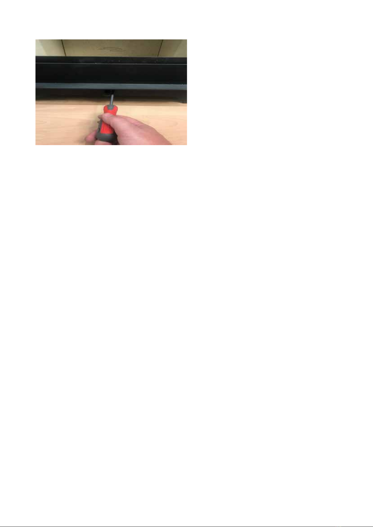
6. You can regulate how vigorously the fire burns by pushing in or
pulling out the lever. The air should NOT be shut right down
allowing the stove to smoulder, to prevent this there is a smoke
control screw which your fitter should have set (see page 10-11).
7. Allow the logs to burn down until you just have red embers and
little or no flame. When adding new fuel, have the logs ready, and
have the door open for as little time as possible to retain the heat in
the stove. Open the door slowly then add 1-3 logs. If the logs have
not shown any signs of lighting after a minute, open the air control
fully and allow the logs to catch light. Repeat until you no longer
wish to run the stove, then allow the fuel to burn out. Do not try to
11
smother the fuel – this will soot up the stove and flue liner, and is
bad for the environment.
Load times will vary depending on the type of wood, its moisture
content, and the amount of wood you load each time.
Never overload the stove. Place the minimum amount of wood
needed to maintain a comfortable room temperature and a clean
burn. Add little and often.
Never shut the stove down until the fuel is well alight and has been
burning for at least 30 minutes.
Never attempt to shut the stove down to keep the fire on overnight.
When the fire has burnt down leaving just embers and you no
longer wish to use it, open the air control fully.
Maintenance and Upkeep
EXCEPT FOR BASIC CLEANING, MAINTENANCE SHOULD ONLY BE
CARRIED OUT BY QUALIFIED INDIVIDUALS.
MAKE SURE THE STOVE IS FULLY COLD BEFORE CARRYING OUT ANY
MAINTENANCE
Door Adjustment
The upper door hinge has an eccentric hinge pin which can be
turned to adjust how tightly the door is held against the stove body.
This can be reached by first removing the short blanking plug above
it.
12
The Icarus 5 is lined with vermiculite boarding which has a high
resistance to heat, but if logs are thrown into the stove rather than
placed, the board be cracked. It is very important to replace any
broken linings as it will have an effect on the stove body temperature
which may cause damage. This would be poor maintenance and not
covered by the guarantee,
In general, small dents or scrapes are OK, cracks or missing parts are
not.
Sweeping the Chimney
Open the door and push up the top vermiculite baffles one at a time
from the centre of the stove until the baffle comes away from the side
lining of the stove. Support the baffle and lower it down into the stove
so it can be removed. Repeat this for the second baffle.
Once the top baffle has been removed the side and rear boards can
be removed. There is now unrestricted access to the flue pipe in the
top of the stove.
13
Ash Removal
Wood burns best on a bed of ash, so, except when the stove is new,
always leave approximately 20mm of ash in the bottom of the stove.
Empty your ash when it is about 40mm deep, leaving the bed of
20mm. Always ensure the ash bed is at least 30mm below the front
lip of the combustion box to prevent logs from rolling out forwards.
Do not compress ash in the stove – this will not allow it to burn, and
will result in throwing away fuel.
When the stove is going to be left for long periods of time it is
advisable to empty the stove of all ash and leave the air control fully
open to allow air to circulate.
Cleaning the Stove Body
Clean the body of the stove with a dry cloth or clean, soft brush. Do
not rub the stove hard or with an abrasive substance as it will mark
the paint.
Glass
Before each lighting clean the glass fully as any ash or dust can be
fired onto the glass with the intense heat. Clean with a ceramic glass
cleaner, alternatively newspaper dipped into the wood ash is a good
substitute.
The most common cause for glass to blacken is running the stove on
wet wood or allowing the stove to smoulder with too little air.
14
Maintenance and Safety
•DO NOT run the stove with broken glass or if the rope seal on
the door is damaged. This will cause the stove to over-burn and
may damage the stove and/or cause a chimney fire.
•
•DO NOT use your stove as an incinerator for rubbish. Only burn
clean wood or wood-based products at 20% moisture or below.
•
•DO NOT run the stove with the door open for extended periods.
Only keep the door open during the lighting stage.
•
•DO NOT use an extractor fan in the same room as the
appliance.
•
•DO NOT FORGET to have your chimney swept at least once a
year by a qualified sweep.
•
•If your chimney catches fire, shut down all air vents. Leave
your house and call 999 immediately.
•
•If your Carbon Monoxide detector goes off, open the doors
and windows then evacuate the room,. Do not re-enter the room
or house until the fire has gone out and/or the alarm has
stopped. Then contact a sweep or engineer to check the flue
and stove before using again.
•
•NEVER share flues with this stove
15
Maintenance and Spare Parts
Key to Components
1
Door rope seal
2
Glass rope seal
3
Glass securing bracket
4
Glass securing screws
5
Glass
6
R/H 25mm fireboard top (6a
L/H)
7
R/H 25mm fireboard bottom
(7a L/H)
8
R/H 25mm fireboard bottom
(8a L/H)
9
R/H 25mm fireboard top (9a
L/H)
10
Lower restrictor plate
11
25mm fireboard base
12
L/H 25mm top baffle
13
Top
14
R/H 25mm rear fireboard
15
R/H 25mm top baffle
16
Customer & Installation Notes
Date of Installation:
Installer Name & contact details
Chimney Swept By:
Date
Notes:
Made in the UK
Burley Appliances Limited
Lands’ End Way
Oakham
Rutland
LE15 6RB
United Kingdom
Further information can be found at:
burley.co.uk/category/wood-burning-stoves/
Email: [email protected]
Phone: 01572 756956
Fax: 01572 724390

Other manuals for Icarus 5

1

Other Burley Stove manuals

Burley Icarus 5 Manual

Burley

Burley Icarus 5 Manual

Burley PICKWORTH 2306 User guide

Burley

Burley PICKWORTH 2306 User guide

Popular Stove manuals by other brands

Muskoka MES30BL-3 Phoenox manual

Muskoka

Muskoka MES30BL-3 Phoenox manual

Smart+ Products SPP-SIFST-S Owners installation and user guide

Smart+ Products

Smart+ Products SPP-SIFST-S Owners installation and user guide

Palazzetti ECOFIRE NINA v2 DESCRIPTION / CLEANING / TECHNICAL DATA

Palazzetti

Palazzetti ECOFIRE NINA v2 DESCRIPTION / CLEANING / TECHNICAL DATA

Bartscher MFG 7340 instruction manual

Bartscher

Bartscher MFG 7340 instruction manual

Optimus International Svea user manual

Optimus International

Optimus International Svea user manual

Coleman 9944-857 Instructions for use

Coleman

Coleman 9944-857 Instructions for use

Jetmaster Mark 2 Gas Coal installation instructions

Jetmaster

Jetmaster Mark 2 Gas Coal installation instructions

Osburn 1100 owner's manual

Osburn

Osburn 1100 owner's manual

Lopi 440-T owner's manual

Lopi

Lopi 440-T owner's manual

Palazzetti ECOFIRE MELITA 6 Installation Instructions and Maintenance Manual

Palazzetti

Palazzetti ECOFIRE MELITA 6 Installation Instructions and Maintenance Manual

Electralog CS4416 owner's manual

Electralog

Electralog CS4416 owner's manual

United States Stove CCS14 owner's manual

United States Stove

United States Stove CCS14 owner's manual

Austro Flamm Scotty Duo User instructions

Austro Flamm

Austro Flamm Scotty Duo User instructions

MAX RANGER 95319 instruction manual

MAX RANGER

MAX RANGER 95319 instruction manual

Eco Spar Auriga 23 kW Manual for installation and operation

Eco Spar

Eco Spar Auriga 23 kW Manual for installation and operation

New Home 600DIS series User - installation - servicing handbook

New Home

New Home 600DIS series User - installation - servicing handbook

Red Stone CFI-470-01 manual

Red Stone

Red Stone CFI-470-01 manual

RCO Kingsman FDV451N installation instructions

RCO

RCO Kingsman FDV451N installation instructions

manuals.online logo
manuals.online logoBrands
  • About & Mission
  • Contact us
  • Privacy Policy
  • Terms and Conditions

Copyright 2025 Manuals.Online. All Rights Reserved.