Burnham DUO-RAD DR-10 Service manual

1
8143914R2-2/04
DNAGNITAREPO,NOITALLATSNI
ROFSNOITCURTSNIECIVRES
DAR-OUD
®
STINUGNILOOC/GNITAEH
nonoitamrofnignikeesnehW.rotcartnocgnitaehruoyllac,tinuotsriaperroecivresroF
.rebmuNledoMedivorp,tinu
r
ebmuNledoM
____-RD
etaDnoitallatsnI
rotcartnoCgnitaeH rebmuNenohP
sserddA
Price $2.00

2
IMPORTANT INFORMATION - READ CAREFULLY
NOTE: The equipment shall be installed in accordance with those installation regulations enforced in the area where the
installation is to be made. These regulations shall be carefully followed in all cases. Authorities having jurisdiction
shall be consulted before installations are made.
All wiring installed in the USA shall be made in accordance with the National Electrical Code and/or local regulations.
All wiring installed in Canada shall be made in accordance with the Canadian Electrical Code and/or local regulations.
The following terms are used throughout this manual to bring attention to the presence of hazards of various risk levels,
or to important information concerning product life.
REGNAD
noitautissuodrazahyltnenimminasetacidnI
,htaednitluserlliw,dediovatonfi,hcihw
ytreporplaitnatsbusroyruj
nisuoires
.egamad
GNINRAW
noitautissuodrazahyllaitnetopasetacidnI
,htaednitluserdluoc,dediovatonfi,hcihw
ytreporplaitnatsbusroyru
jnisuoires
.egamad
NOITUAC
noitautissuodrazahyllaitnetopasetacidnI
nitluseryam,dediovatonfi,hcihw
ytreporproyrujnironimroetaredom
.
egamad
ECITON
nosnoitcurtsnilaicepssetacidnI
ecnanetniamro,noitarepo,noitallatsni
otdetalertontubtnatropmierahcihw
.sd
razahyrujnilanosrep
ECITON
.launamsihtfokcabehtnodetnirpsihcihwfoypoca,ytnarrawdetimilasahecnailppasihT
dellatsniyltcerroceraslor
tnocllatahteesotrotcartnocgnillatsniehtfoytilibisnopserehtsitI
.etelpmocsinoitallatsniehtnehwylreporpg
nitarepoeradna
GNINRAW
ehtwolloF.ylefasetarepootecivresdnaecnanetniamralugerseriuqerecnailppasihT
.launamsihtnideniatnocsnoit
curtsni
ytreporpesuacnacecnanetniamroecivres,noitaretla,tnemtsujda,noitallatsnireporpmI
erofeblaunameri
tneehtdnatsrednudnadaeR.efilfossolroyrujnilanosrep,egamad
ebtsumecivresdnanoitallatsnI.ecivresro,noita
repopu-trats,noitallatsnignitpmetta
.ycnegaecivresrorellatsnielbaegdelwonkdna,delliks,decneirepxenayby
lnodemrofrep
epipynawercsnutonoD.erusserphgihrednuretawtohyrevsniatnocecnailppasihT
siretawehtgnirussay
levitisoptuohtiwstnenopmocynatcennocsidottpmettaronsgnittif
tohyrevemocebhcihwstnenopmocsniatnocecnail
ppasihT.erusserponsahdnalooc
.loocerayehtsselnustnenopmocynahcuottonoD.gnitareponehw
.semitllataecalpni
ebtsumsdraugdnaserusolcne,setalprevocllA

3
Table of Contents
I. Pre-Installation ..................................... 4
II. Unpack Appliance ................................ 4
III. Installation............................................ 4
IV. Water Piping......................................... 5
V. Electrical............................................... 9
VI. Condensate Drain ............................... 12
VII. System Start-up .................................. 12
VIII. Service ................................................ 13
IX. Repair Parts ........................................ 15
Figure 1: Dimensional Drawing
ledoM ]sehcnini[snoisnemiD etamixorppA
)sbl(thgieWgnippihS
AB
01-RD8/5-614133
51-RD238/5-9255
22-RD238/5-9236
Table 1: Dimensional Data

4
II. Unpack Appliance
A. Move appliance to approximate installed position.
A.Inspect shipment carefully for any signs of damage.
All equipment is carefully manufactured, inspected and
packed. Our responsibility ceases upon delivery of the
equipment to the carrier in good condition. Any
claims for damage or shortage in shipment must be
filed immediately against the carrier by the consignee.
No claims for variances or shortages will be allowed by
the manufacturer unless presented within sixty (60)
days after receipt of equipment.
B. Combined heating and cooling systems must have
provisions for isolating one service when the other is
operating. The heating and/or cooling system design
and installation must conform to the requirements of
I. Pre-Installation
the authority having jurisdiction. In the absence of
such requirements, the design and installation must
conform to recognized industry Codes such as those
published by ARI, ASHRAE and I=B=R.
C. The appliance may be installed on either inside or
outside walls; however installation on outside walls
will provide greater comfort. Cooling units require
disposal of condensate and may influence the position
of the unit. The most effective position is centrally on
a long wall, but if a room is excessively long it may be
preferable to install a smaller unit at either end of the
room instead of one larger unit. The quietest operation
of the units will be on a solid wall; flimsy partitions
promote vibration.
NOITUAC
.ecnailppapordtonoD
.segdeprahsfoeraweB
GNINRAW
ebdluohsecnailppasihtfonoitallatsnI
delliksdnadeniartybylnonekatrednu
.ycnegaecivresdeifilauqamorflenno
srep
III. Installation
A. Remove front cover by unscrewing cover knobs and fan
control knob(s). Carefully pull cover forward and set
aside.
B. Place appliance in its installed location.
C. Level appliance, using shims if required.
D. Install appliance
1. Freestanding Models
Secure to wall with screws installed through the
back panel.
2. RecessedModels
Secure to adjacent framing studs with adjustable
attaching flanges provided on sides of the unit.
B. Remove all packaging.

5
A. Design and install system piping to prevent oxygen
contamination of appliance water and frequent water
additions.
1. There are many possible causes of oxygen contami-
nation such as:
a. Addition of excessive make-up water as a result
of system leaks.
b. Absorption through open tanks and fittings.
c. Oxygen permeable materials in the distribution
system.
2. In order to insure long product life, oxygen sources
must be eliminated. This can be accomplished by
taking the following measures:
a. Repairing system leaks to eliminate the need for
addition of make-up water.
b. Eliminating open tanks from the system.
c. Eliminating and/or repairing fittings which
allow oxygen absorption.
d. Use of non-permeable materials in the distribu-
tion system.
e. Use properly designed and operating air
elimination devices in water piping.
B. Connect system supply and return piping to appliance.
The supply piping should be connected to the front
connection of the coil to ensure proper venting. See
Figures 1, 3 and 4. Also consult I=B=R Installation and
PipingGuides.Maintainminimum½inchclearancefrom
hot water piping to combustible materials.
IV. Water Piping
C. Units must be assured an adequate supply of hot or
chilled water by proper sizing of the distribution
system, circulator and balancing provisions.
D. Supply and return piping may penetrate unit from the
bottom, rear or side (recessed units only). See Figure 2.
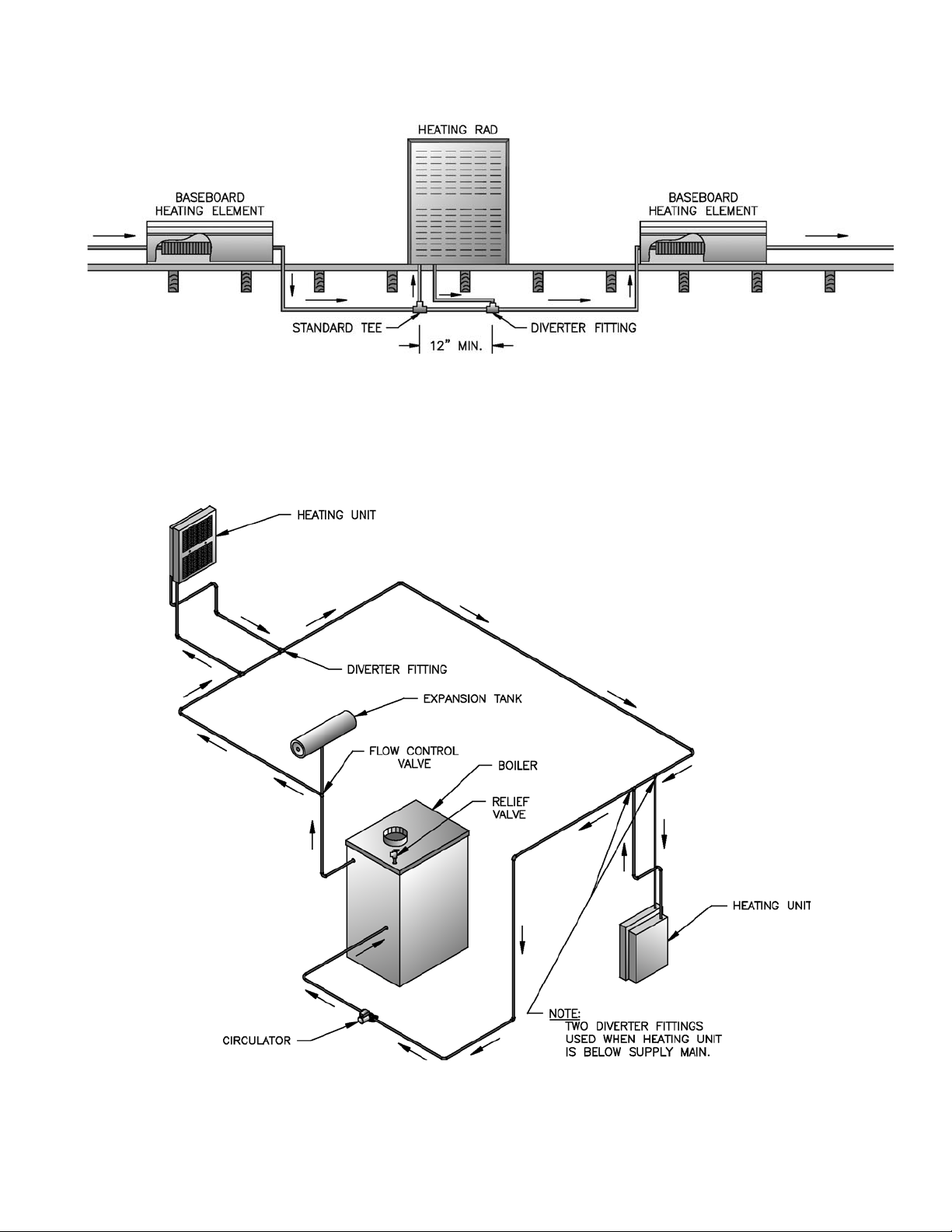
E. The heating units may be installed in a one-pipe system
with diverter fitting(s) for heating application only. The
location and quantity of diverter fitting(s) will affect the
flow to the unit. A single fitting located on the return
fromtheunitwillprovideminimalflow. Asinglefitting
located on the supply to the unit will provide increased
flow. Two fittings, one located on the supply and one
located on the return of the unit will provide the
maximumflowtotheunit. Consultthemanufacturer’s
instructions of the diverter fitting for additional informa-
tion. See Figure 3.
F. When the installation is to provide for heating and
cooling, it is highly recommended that a two pipe
reverse return distribution system be used. See Figure4.
It is also recommended that any piping carrying chilled
water be insulated and sealed with a suitable sealant as
necessary, to ensure condensation does not spill or
leak.
G. Before making connections to the units, the piping
should be flushed with water to remove dirt and
foreign matter from accumulating in the system.
ECITON
otegamaddnanoitareporeporpminitluseryamecnailppaepipylreporpoteruliaF
reporpehtfodnaeerfkaelyletulosba
signipipretawerussasyawlA.erutcurtsroecnailppa
.epytdnaezis
fonoitanimatnocnegyxoybdesuacsmelborprevoct
onseodytnarraWdradnatSs'mahnruB
.retawfonoitiddatneuqerfybdesuacpu-dliub)emil(elacsroretawecnailppa

6
Figure 2: Water Piping Penetrations for Recessed and Free Standing Models

7
Figure 3: Typical Piping for One Pipe Heating Units

8
Figure 4: Typical Piping for Two Pipe Reverse Return Heating and Cooling Units

9
V. Electrical
A. Install wiring and electrically ground appliance in
accordance with authority having jurisdiction or, in the
absence of such requirements, follow the National
Electrical Code, ANSI/NFPA 70, and/or CSA C22.1
Electrical Code.
1. Refer to Code(s) for proper size and type of wire
required. Follow Code(s).
2. Use anti-short bushings on all wiring passing
through appliance, junction box and/or control
boxes.
3. Use armored cable (BX) over all exposed line
voltage wiring.
B. Install thermostat(s) in accordance with the recommen-
dations included with the manufacturer’s instructions.
REGNAD
ecivresronoitallatsnignitpmettaerofebderewopnuerasnoitcennoclacirtcelellaerussaylevitisoP
sexoblacirtcelellatuokcoL.gnidliubroecnailppaehtfosnoitcennocrostnenopmoclacirtcelefo
.ffodenrutsirewopecnokcoldaphtiw
GNINRAW
suoiresnitluseryamecnailppaehtotsnoitcennoclacirtceleeriwylreporpoteruliaF
.mrahlacisyhp
erofebffosirewopllaerusekaM.ecruosenonahterommorfebyamrewoplacirtcelE
.krowlacirtceleynagnitpmetta
.tcennocsiddesufdezisylreporpahtiwdetcetorpebtsumecnailppahcaE
.slortnocgnitareporoytefasynaevitareponiekamrotuopmujreveN
esehT.ylnotsetyrotcafroftinuehtmorfgnidurtorpsdaellacirtcelehtiwdeppihssitinU
.rellatsniehtybdevomere
btsumdnanoitcennoclacirtcelerofelbatiustonerasdael
C. Remove factory electrical test leads from the unit.
These leads are not suitable for connection.
D. Connect the main power supply and ground from fused
disconnect to appliance. Install an electrical service
switch in the line voltage “Hot” leg of the power
supply. Locate the service switch such that the
appliance can be shut-off without exposing personnel
to danger in the event of an emergency.
E. Refer to Figures 5 and 6 for details on typical heating
and combination heating and cooling system wiring
diagrams.
F. Consult control manufacturer for appropriate selection
of controls and relays to accommodate the respective
electrical loads.

10
Figure 5: Unit Wiring Diagram with Optional Thermostat Control of Circulator and Unit

11
Figure 6: Automatically Controlled Boiler, Chiller and Heating & Cooling Wiring Diagram

12
A. Verify the water piping and electrical system are
installed properly. Refer to installation instructions
contained in this manual.
B. Confirm all electrical and water is turned off at the
source.
GNINRAW
llawollofdnadnatsrednu,daeryletelpmoC
erofeblaunamsihtnisnoitcurtsni
.putratsgnitpmetta
C. Fill system with water and vent air from system begin-
ning with the lowest unit in the system. Vent air from
the coil by unscrewing the air bleed valve, no more than
two (2) turns, located at the top of the coil. Close air
bleed valve when complete.
D. Confirm that the appliance and system have no water
leaks.
VII. System Start-up
GNINRAW
foerusserpretawtelnimumixamehT
reveN.gisp541siecnailppasiht
.erusserpsihtdeecxe
erutarepmetretawtelnimumixamehT
reveN.F°002siecnailppasihtfo
.erutarepmetsihtdeecxe
E.Reinstall cover with previously removed knobs.
F. Turn power on to Appliance.
G. Check thermostat operation. Raise and lower tempera-
ture setting to start and stop appliance operation.
H. Review manual and system operation with owner or
operator. A variable speed fan control knob controls
the appliance output. See Figure 1. The unit will
operate with the knob in any position except for the
“OFF” position.
A. Cooling units contain a condensate drain connection.
Attach tube to the condensate drip pan connection and
fasten.
ECITON
metsysetasnednocepipylreporpoteruliaF
tonoD.efilecnailppaecuderyltaerglliw
etasnednocnosevlavrospac,sgu
lpllatsni
etasnednocfoezisecudertonoD.gnipip
reporprofsedoClacoLtlusnoC.gnipip
.tnemegnarragnipipegrahcs
id
B. Pipe condensate to a floor drain or condensate pump/
sump.
VI. Condensate Drains
ECITON
nisipartetasnednoctcepsniyllacidoireP
.redrognikrowreporp
C. Each appliance requires a separate condensate drain
line. Do not manifold condensate drains from multiple
appliances together.
D. A common condensate pump/sump may be used. Run
separate condensate piping from each appliance to the
sump. A common drain may be used to discharge
condensate from the sump.
E. If a common pump/sump is used, individual appliance
drain lines must be connected such that one drain pipe
cannot back feed into another appliance drain.

13
VIII. Service
REGNAD
hgihrednuretawtohyrevdna,strapgnivom,yticirtceleegatlovhgihsesuecnailppasihT
sierutarepmetretawehttaht
dnaffoeraseilppusrewopcirtcelellatahterussA.erusserp
.ecivresroylbmessasidynagnitpmettaerofeblooc
roylb
messasidynagnitpmettaerofebffoerasehctiwstcennocsidlacirtcelellatahterussA
.ecivres
.ecivedlortnocynaht
iwrepmatroevomer,yfidomreveN
GNINRAW
ecivresdecneirepxednadelliksybderiaperdnadecivresebylnotsumecnailppasihT
.snaicinhcet
.sledomlacitnedih
tiwdecalperebtsumyeht,decalpereraslortnocynafI
snoitcesehtllanideniatnocsgninrawdnasnoitcurtsniehtllaw
ollofdnadnatsrednu,daeR
.launamsihtfo
erussadnaseriwehtlebalylraelc,ecivresgniruddetcennocsideraseriwla
cirtceleynafI
.ylreporpdetcennocereraseriwehttaht
.ecnailppasihtfotnenopmocrolortnocgnitareporoytefasyn
assapybrotuopmujreveN
erofebylreporpgnitarepoerastnenopmocdnaslortnocgnitarepodnaytefasllatahterussA
.e
civresnikcabecnailppaehtgnicalp
A. GENERAL
Inspection and service should be conducted annually.
Turn off electrical power while conducting service or
maintenance.
B. FILTER
The filter should be inspected periodically and cleaned
as required. Remove front cover on unit for access to
filter. Gently tap out any loose dirt and if required the
filter can be cleaned in warm water with a mild
detergent. After washing, gently shake excess water
from filter and allow to dry. Reinstall filter and cover.
ECITON
ylivaehemocebotretlifehtwollareveN
lliwsihtsatriddnatnilhtiwdeggolc
dna,tinuehtfoycneiciffeehtriapmi
.)s
(rotomnafehtotegamadesuacyam
.retliftuohtiwtinuetareporeveN
C. VENTING
The system should be vented at the time the system is
filled with water and at the beginning of each heating
and cooling season.
D. COIL
The coil should be checked periodically and cleaned
with a vacuum cleaner. If required on cooling units
only (with drain pans) the coil can be cleaned with hot
water and a mild detergent as may be necessary.
E. DRAIN PAN (Cooling Units Only)
Clean the drain pan at the beginning and end of a
summer cooling season - remove all sediment or lint at
the drain pan outlet to be sure that drain is functioning
properly.

14
EDIUGGNITOOHSELBUORT
TNIALPMOC ESUAC YDEMER
gniloocrognitaehoNliocdnuobriA
tfahsrotomnognippilsnaF
gnitarepotonrotomnaF
ylreporpgnitarepotonrellihcro
relioB
liocmorfriatneV
wercstesnafnethgiT
nwolb,noitpurretnirewoprofkcehC
.slanimretesoolroesuf
evomer,rot
omehtotrewopsierehtfI
.decalperroderiaperevahdnarotom
namecivresllaC
wolfriafoytitnauqtneiciffusnIretlify
triD
tfahsrotomnognippilsnaF
retlifnaelcroecalpeR
wercstesnafnethgiT
esioNgnippilsnafronafesooL
metsysniriA
deepsnafevissecxE
dnatfahsrotomnonoitisoproftsujdA
eruces
snoitacoldeelbllatariatneV
etadommoccaotdeepsnafecudeR
regnolhtiwstnemeriuqertrofmoc
.selcycgnitarepo

15
IX. Repair Parts
All DUO-RAD® Repair Parts may be obtained through your local Burnham Wholesale distributor.
Should you require assistance in locating a Burnham distributor in your area, or have questions regarding
the availability of Burnham products or repair parts, please contact Burnham Customer Service at (717)
481-8400 or Fax (717) 481-8408.
SERVICE RECORD
DATE SERVICE PERFORMED
yeK
.oN noitpircseD rebmuNtraP]ytitnauQ[
01-RD51-RD22-RD
1retliF 8093118]1[9093118]1[
2)gnitaeH(lioC818093508]1[918093508]1[
)gnilooC(lioC 109093508]1[209093508]1[
3ro
toM 900193318]1[900193318]2[
4)naF(bonKlortnoC03906808]1[
5)revoC(bonK62906808]2[
6lortnoCdeepSnaF010193318]1[
7)
gnidnatseerF(revoCtnorF60093408]1[70093408]1[
)desseceR(revoCtnorF80093408]1[90093408]1[
8)rotoM(tnuoMnoital
osI75906808]3[75906808]6[
9naPpirDetasnednoC309093508409093508

16
LimitedWarranty– Except as provided below with respect to products or parts not manufactured by U.S. Boiler Co., Inc.
U.S. Boiler Co., Inc. warrants to the original owner at the original installation site that products manufactured by U.S. Boiler Co.,
Inc. comply, at the time of manufacture, with recognized Hydronics industry regulatory agency standards and requirements then in
effect and will be free from defects in materials and workmanship for a period of one year after the date of installation.
The remedy for breach of this warranty is expressly limited to the repair or replacement of any part found to be defective
under conditions of normal use and does not extend to liability for incidental, special or consequential damages or losses such as
loss of the use of the products, inconvenience, loss of time or labor expense involved in repairing or replacing alleged defective
product. U.S. Boiler Co., Inc. shall have no responsibility for the performance of any product sold by it under conditions varying
materially from those under which such product is usually tested under existing industry standards, nor for any damage to the
product from abrasion, erosion, corrosion, deterioration or the like due to abnormal temperatures or the influence of foreign matter
or energy, nor for the design or operation of any system of which any such product may be made a part or for the suitability of any
such product for any particular application.
For products or parts not manufactured by U.S. Boiler Co., Inc., the warranty obligation of U.S. Boiler Co., Inc. shall, in all
respects, conform and be limited to the warranty actually extended to U.S. Boiler Co., Inc. by its vendors.
Warranty service can be obtained by contacting the original installer of the product and providing him with a detailed
description of any apparent defect. If this procedure fails to result in satisfactory warranty service, the owner should notify U.S.
Boiler Co., Inc., P.O. Box 3079, Lancaster, PA 17604. Transportation to a factory or other designated facility for repairs of any
products or items alleged defective shall, in all events, be the responsibility and at the cost of the owner.
Notwithstanding any of the above provision, (1) failures resulting from misuse, improper installation or lack of
maintenance are not covered by this warranty, and (2) U.S. Boiler Co., Inc.’s liability under this warranty shall not exceed the selling
price of the product found to be defective.
Equipment furnished by the Buyer, either mounted or unmounted, and when contracted for by the Buyer to be installed or
handled is not covered by this warranty. U.S. Boiler Co., Inc. does not assume any responsibility in connection with such
equipment, operation, warranty, performance, or any other liability connected thereto.
Then foregoing provisions of this WARRANTYshall be effective to the maximum extent permitted by applicable law, and,
to the extent that any such provision would otherwise have an unconscionable result or would otherwise be inconsistent with
applicable law, such provision shall be limited in effect to the minimum extent necessary to avoid such unconscionable result or
inconsistency with applicable law.
Any implied warranties, including implied warranties of merchantability and fitness for a particular purpose shall, to the
extent permitted by applicable law, be limited in duration to a period of one year after the date of installation. To the extent
permitted by applicable law, the remedies for breach of any such implied warranty shall be limited to the remedies set forth above
with respect to a breach of the express limited warranty provided. With respect to the limitations on implied warranties set forth
above, U.S. Boiler Co., Inc. hereby notifies each person to whom such warranty is made as follows: Some states do not allow
limitations on how long an implied warranty lasts or the exclusion or limitation of incidental or consequential damages, so the
above limitations, or exclusions may not apply to you. This warranty gives you specific legal rights, and you may also have other
rights which vary from state to state.
Limited Warranty
DUO-RAD®,DUO-RAD®II AND CAST IRON RADIATION
3/03
This manual suits for next models
2
Table of contents