PART 1 –SYSTEM OVERVIEW
MYX-12383 REPLICATOR 1100 (for AC lifters)
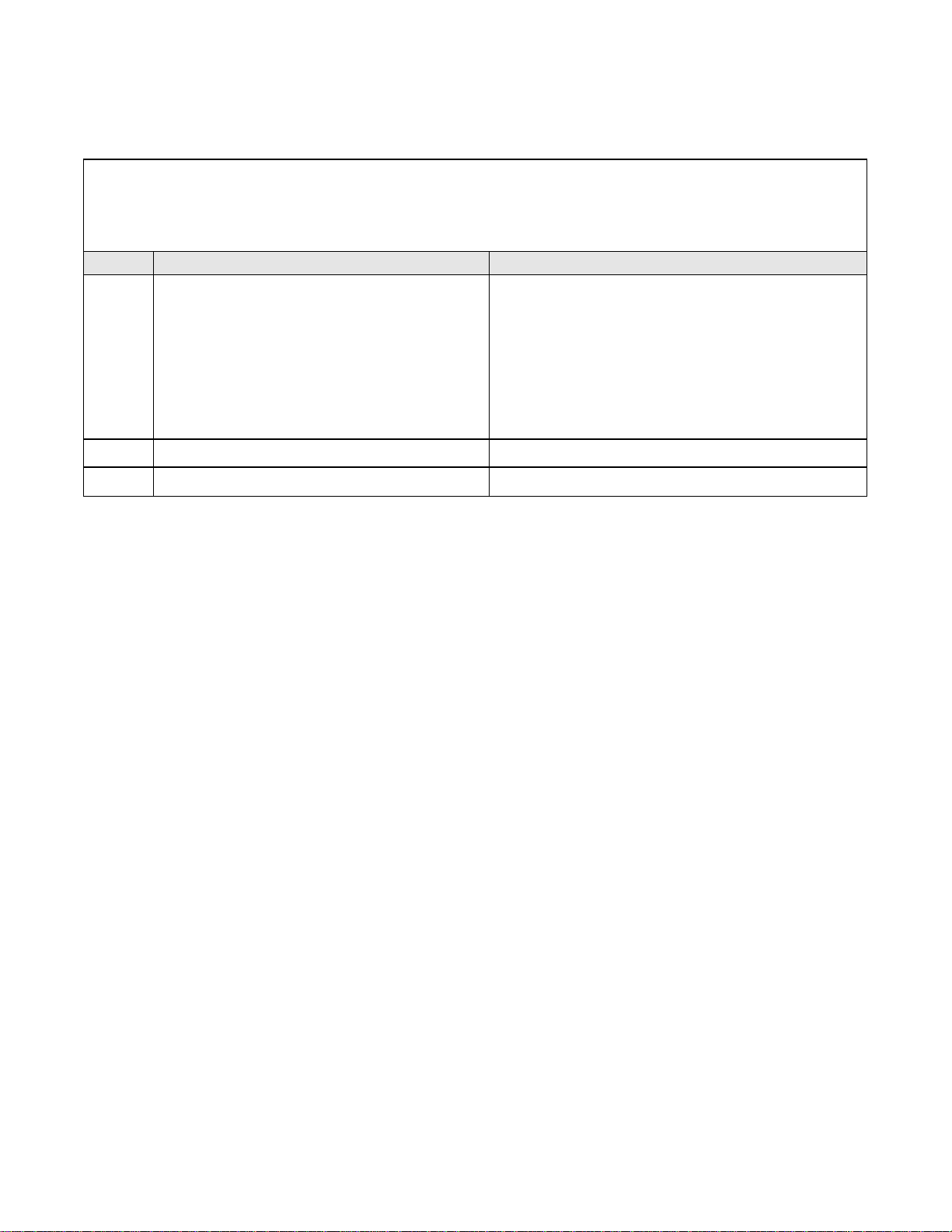
“SOL”connector I/O ratings
Note: All solenoids are served by the same fuse, FU2, 6.3 A, on the
rear panel. Maximum total current of the solenoids is limited by this
fuse.
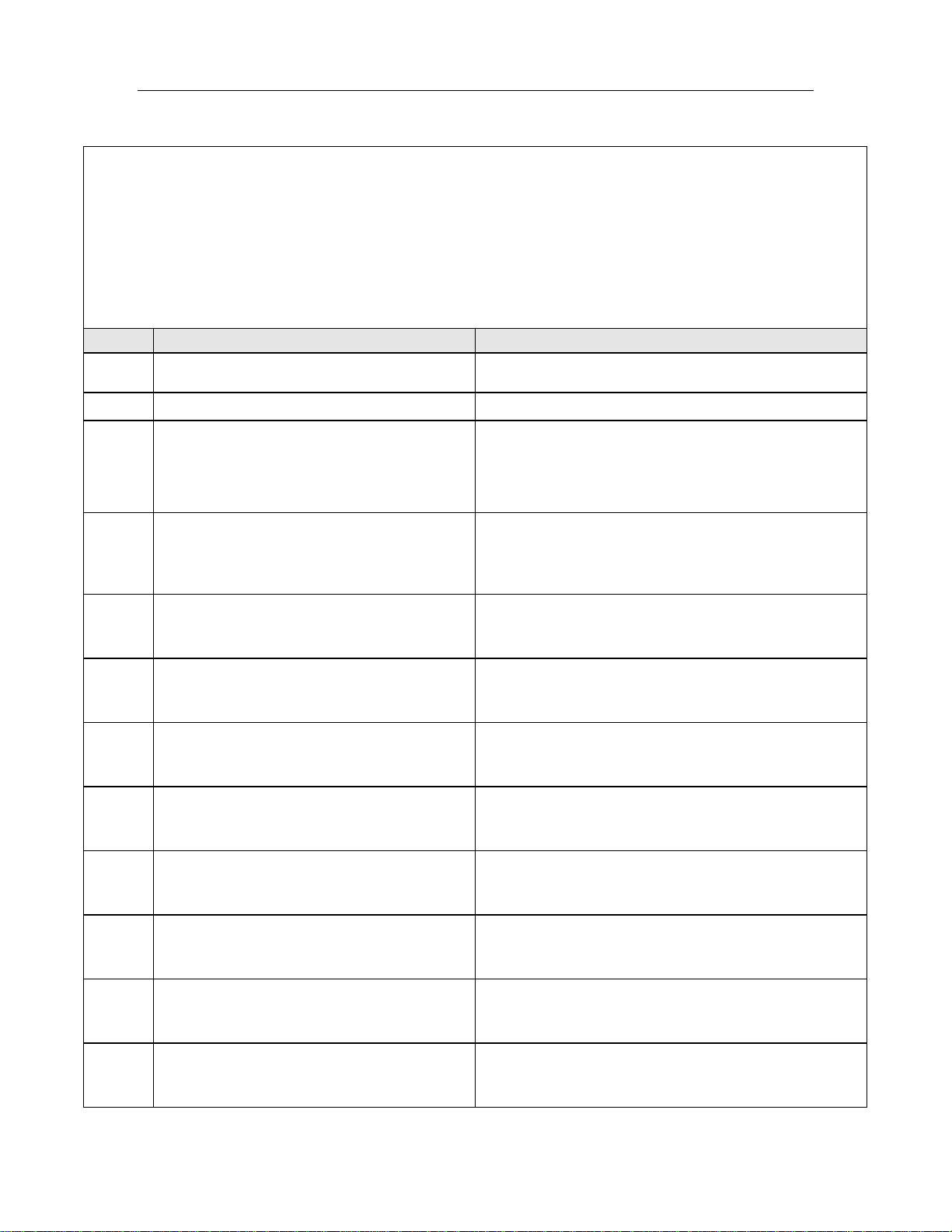
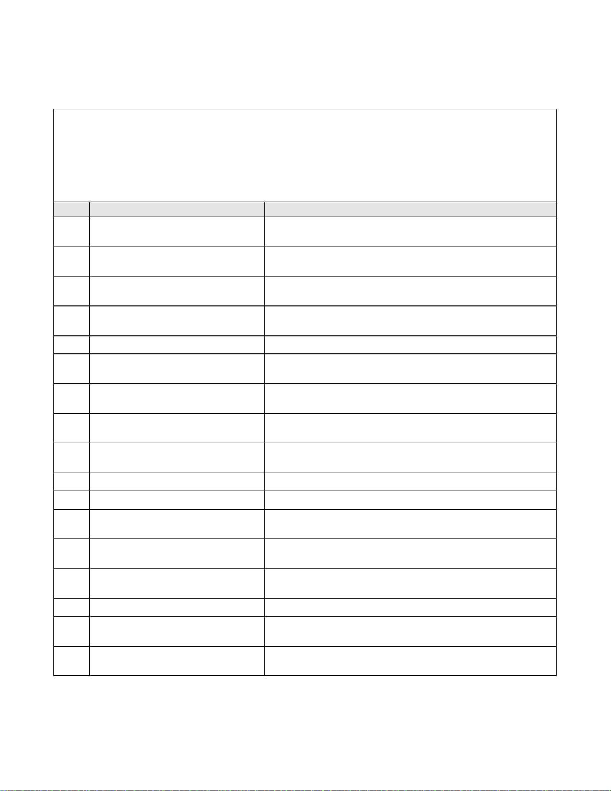
PIN # DESCRIPTION RATINGS
9Input -Solenoid Hot 24 V max AC, 50/60 Hz, or 24 V max DC, 6.3 A max
33 Input -Solenoid Neutral Neutral or common for pin 9
2, 6,
11, 17,
21, 24,
35, 30
Output -Solenoid Neutral Neutral or common for pins 1, 5, 10, 16, 20, 23, 34,
and 29
3, 7,
12, 18,
22, 25,
36, 31
Chassis ground 18 AWG wire
1Oxygen Vent Solenoid Output 24 V max AC, 50/60 Hz, or 24 V max DC.
2 A max, but on same 6.3 A fuse, FU2 with 7 other
solenoid outputs.
5Second Stage Cut O2 Solenoid Output 24 V max AC, 50/60 Hz, or 24 V max DC.
2A max, but on same 6.3 A fuse, FU2 with 7 other
solenoid outputs.
10 Lo Preheat Solenoid Output 24 V max AC, 50/60 Hz, or 24 V max DC.
2 A max, but on same 6.3 A fuse, FU2 with 7 other
solenoid outputs.
16 Ignite Solenoid Output 24 V max AC, 50/60 Hz, or 24 V max DC.
2 A max, but on same 6.3 A fuse, FU2 with 7 other
solenoid outputs.
20 First Stage Cut Oxygen Solenoid Output 24 V max AC, 50/60 Hz, or 24 V max DC.
2 A max, but on same 6.3 A fuse, FU2 with 7 other
solenoid outputs.
23 Water Solenoid Output 24 V max AC, 50/60 Hz, or 24 V max DC.
2 A max, but on same 6.3 A fuse, FU2 with 7 other
solenoid outputs.
34 Hi Preheat Solenoid Output 24 V max AC, 50/60 Hz, or 24 V max DC.
2 A max, but on same 6.3 A fuse, FU2 with 7 other
solenoid outputs.
29 Auxilliary Solenoid Output 24 V max AC, 50/60 Hz, or 24 V max DC.
2 A max, but on same 6.3 A fuse, FU2 with 7 other
solenoid outputs.