Makita DTW284 User manual

DTW284
DTW285
EN Cordless Impact Wrench INSTRUCTION MANUAL 4
PL Akumulatorowy klucz
udarowy INSTRUKCJA OBSŁUGI 11
HU Akkumulátoros csavarkulcs HASZNÁLATI KÉZIKÖNYV 18
SK Akumulátorový razový
uťahovač NÁVOD NA OBSLUHU 25
CS Akumulátorový rázový
utahovák NÁVOD K OBSLUZE 32
UK Бездротовий ударний
гайковерт ІНСТРУКЦІЯ З
ЕКСПЛУАТАЦІЇ 39
RO Maşină de înşurubat cu
impact cu acumulator MANUAL DE INSTRUCŢIUNI 47
DE Akku-Schlagschrauber BETRIEBSANLEITUNG 54

1
2
3
Fig.1
1
Fig.2
1
2
Fig.3
1
Fig.4
1
Fig.5
1
Fig.6
1
Fig.7
1
A
B
Fig.8
2

1
2
3
4
5
6
Fig.9
1
2
Fig.10
1
2
3
Fig.11
2
3
1
Fig.12
Fig.13
3

4ENGLISH
ENGLISH (Original instructions)
SPECIFICATIONS
Model: DTW284 DTW285
Fastening capacities Standard bolt M10 - M20
High tensile bolt M10 - M16
Square drive 12.7 mm
No load speed Hard impact mode 0 - 2,800 min-1
Medium impact mode 0 - 2,100 min-1
Soft impact mode 0 - 1,600 min-1
Impacts per minute Hard impact mode 0 - 3,500 min-1
Medium impact mode 0 - 2,600 min-1
Soft impact mode 0 - 1,800 min-1
Overall length 147 mm
Rated voltage D.C. 14.4 V D.C. 18 V
Net weight 1.4 - 1.6 kg 1.5 - 1.8 kg
• Duetoourcontinuingprogramofresearchanddevelopment,thespecicationshereinaresubjecttochange
without notice.
• Specicationsmaydifferfromcountrytocountry.
• Theweightmaydifferdependingontheattachment(s),includingthebatterycartridge.Thelightestandheavi-
est combination, according to EPTA-Procedure 01/2014, are shown in the table.
Applicable battery cartridge and charger
Batterycartridge D.C.14.4 V Model BL1415N / BL1430 / BL1430B / BL1440 / BL1450 / BL1460B
D.C.18 V Model BL1815N / BL1820 / BL1820B / BL1830 / BL1830B / BL1840 /
BL1840B / BL1850 / BL1850B / BL1860B
Charger DC18RC / DC18RD / DC18RE / DC18SD / DC18SE / DC18SF
• Someofthebatterycartridgesandchargerslistedabovemaynotbeavailabledependingonyourregionof
residence.
WARNING: Only use the battery cartridges and chargers listed above.Useofanyotherbatterycartridges
andchargersmaycauseinjuryand/orre.
Intended use
The tool is intended for fastening bolts and nuts.
Noise
ThetypicalA-weightednoiseleveldeterminedaccord-
ing to EN62841:
Soundpressurelevel(LpA):96dB(A)
Soundpowerlevel(LWA):107dB(A)
Uncertainty(K):3dB(A)
WARNING: Wear ear protection.
Vibration
Thevibrationtotalvalue(tri-axialvectorsum)deter-
mined according to EN62841:
Model DTW284
Workmode:impacttighteningoffastenersofthemaxi-
mumcapacityofthetool
Vibrationemission(ah):14.0m/s2
Uncertainty(K):1.5m/s2
Model DTW285
Workmode:impacttighteningoffastenersofthemaxi-
mumcapacityofthetool
Vibrationemission(ah):11.5m/s2
Uncertainty(K):1.5m/s2
NOTE:
The declared vibration emission value has been
measured in accordance with the standard test method
andmaybeusedforcomparingonetoolwithanother.
NOTE:
Thedeclaredvibrationemissionvaluemay
alsobeusedinapreliminaryassessmentofexposure.
WARNING: The vibration emission during actual
use of the power tool can differ from the declared
emissionvaluedependingonthewaysinwhichthe
tool is used.
WARNING:Besuretoidentifysafetymeasures
to protect the operator that are based on an estima-
tionofexposureintheactualconditionsofuse(taking
accountofallpartsoftheoperatingcyclesuchas
the times when the tool is switched off and when it is
runningidleinadditiontothetriggertime).

5ENGLISH
EC Declaration of Conformity
For European countries only
TheECdeclarationofconformityisincludedasAnnexA
to this instruction manual.
SAFETY WARNINGS
General power tool safety warnings
WARNING: Read all safety warnings, instruc-
tions, illustrations and specications provided
with this power tool. Failure to follow all instructions
listedbelowmayresultinelectricshock,reand/or
seriousinjury.
Save all warnings and instruc-
tions for future reference.
Theterm"powertool"inthewarningsreferstoyour
mains-operated(corded)powertoolorbattery-operated
(cordless)powertool.
Cordless impact wrench safety warnings
1. Hold the power tool by insulated gripping
surfaces, when performing an operation
where the fastener may contact hidden wiring.
Fastenerscontactinga"live"wiremaymake
exposedmetalpartsofthepowertool"live"and
could give the operator an electric shock.
2. Wear ear protectors.
3. Check the impact socket carefully for wear,
cracks or damage before installation.
4. Hold the tool rmly.
5. Keep hands away from rotating parts.
6. Always be sure you have a rm footing.
Be sure no one is below when using the tool in
high locations.
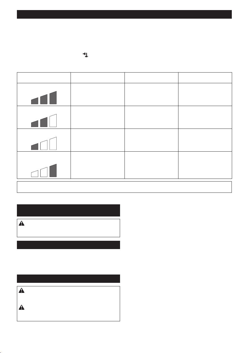
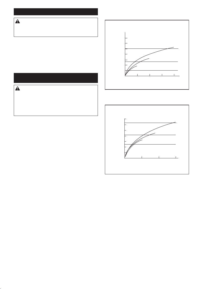
7. The proper fastening torque may differ
depending upon the kind or size of the bolt.
Check the torque with a torque wrench.
SAVE THESE INSTRUCTIONS.
WARNING:
DO NOT let comfort or familiarity
with product (gained from repeated use) replace strict
adherence to safety rules for the subject product.
MISUSE or failure to follow the safety rules stated in this
instruction manual may cause serious personal injury.
Important safety instructions for
battery cartridge
1.
Before using battery cartridge, read all instruc-
tions and cautionary markings on (1) battery char-
ger, (2) battery, and (3) product using battery.
2. Do not disassemble battery cartridge.
3. If operating time has become excessively
shorter, stop operating immediately. It may
result in a risk of overheating, possible burns
and even an explosion.
4.
If electrolyte gets into your eyes, rinse them out
with clear water and seek medical attention right
away. It may result in loss of your eyesight.
5. Do not short the battery cartridge:
(1) Do not touch the terminals with any con-
ductive material.
(2) Avoid storing battery cartridge in a con-
tainer with other metal objects such as
nails, coins, etc.
(3) Do not expose battery cartridge to water
or rain.
A battery short can cause a large current
ow, overheating, possible burns and even a
breakdown.
6. Do not store the tool and battery cartridge in
locations where the temperature may reach or
exceed 50 °C (122 °F).
7. Do not incinerate the battery cartridge even if
it is severely damaged or is completely worn
out. The battery cartridge can explode in a re.
8. Be careful not to drop or strike battery.
9. Do not use a damaged battery.
10.
The contained lithium-ion batteries are subject to
the Dangerous Goods Legislation requirements.
Forcommercialtransportse.g.bythirdparties,
forwarding agents, special requirement on pack-
aging and labeling must be observed.
For preparation of the item being shipped, consult-
inganexpertforhazardousmaterialisrequired.
Pleasealsoobservepossiblymoredetailed
national regulations.
Tape or mask off open contacts and pack up the
batteryinsuchamannerthatitcannotmove
around in the packaging.
11. Follow your local regulations relating to dis-
posal of battery.
12. Use the batteries only with the products
specied by Makita. Installing the batteries to
non-compliantproductsmayresultinare,exces-
siveheat,explosion,orleakofelectrolyte.
SAVE THESE INSTRUCTIONS.
CAUTION: Only use genuine Makita batteries.
Use of non-genuine Makita batteries, or batteries that
havebeenaltered,mayresultinthebatterybursting
causingres,personalinjuryanddamage.Itwill
alsovoidtheMakitawarrantyfortheMakitatooland
charger.
Tips for maintaining maximum
battery life
1. Charge the battery cartridge before completely
discharged. Always stop tool operation and
charge the battery cartridge when you notice
less tool power.
2. Never recharge a fully charged battery car-
tridge. Overcharging shortens the battery
service life.
3.
Charge the battery cartridge with room tempera-
ture at 10 °C - 40 °C (50 °F - 104 °F). Let a hot
battery cartridge cool down before charging it.
4. Charge the battery cartridge if you do not use
it for a long period (more than six months).

6ENGLISH
FUNCTIONAL
DESCRIPTION
CAUTION: Always be sure that the tool is
switched off and the battery cartridge is removed
before adjusting or checking function on the tool.
Installing or removing battery
cartridge
CAUTION: Always switch off the tool before
installing or removing of the battery cartridge.
CAUTION: Hold the tool and the battery car-
tridge rmly when installing or removing battery
cartridge.Failuretoholdthetoolandthebattery
cartridgermlymaycausethemtoslipoffyourhands
andresultindamagetothetoolandbatterycartridge
andapersonalinjury.
►Fig.1: 1. Red indicator 2. Button 3.Batterycartridge
Toremovethebatterycartridge,slideitfromthetool
while sliding the button on the front of the cartridge.
Toinstallthebatterycartridge,alignthetongueonthe
batterycartridgewiththegrooveinthehousingandslip
itintoplace.Insertitallthewayuntilitlocksinplace
withalittleclick.Ifyoucanseetheredindicatoronthe
uppersideofthebutton,itisnotlockedcompletely.
CAUTION: Always install the battery cartridge
fully until the red indicator cannot be seen. If not,
itmayaccidentallyfalloutofthetool,causinginjuryto
youorsomeonearoundyou.
CAUTION: Do not install the battery cartridge
forcibly.Ifthecartridgedoesnotslideineasily,itis
notbeinginsertedcorrectly.
Battery protection system
Lithium-ion battery with star marking
►Fig.2: 1. Star marking
Lithium-ion batteries with a star marking are equipped
withaprotectionsystem.Thissystemautomatically
cutsoffpowertothetooltoextendbatterylife.
Thetoolwillautomaticallystopduringoperationifthe
tooland/orbatteryareplacedunderoneofthefollowing
conditions:
Overloaded:
The tool is operated in a manner that causes it to draw
anabnormallyhighcurrent.
In this situation, turn the tool off and stop the application
that caused the tool to become overloaded. Then turn
the tool on to restart.
Ifthetooldoesnotstart,thebatteryisoverheated.In
thissituation,letthebatterycoolbeforeturningthetool
on again.
Low battery voltage:
Theremainingbatterycapacityistoolowandthetool
will not operate. In this situation, remove and recharge
thebattery.
Indicating the remaining battery
capacity
Only for battery cartridges with the indicator
►Fig.3: 1. Indicator lamps 2. Check button
Pressthecheckbuttononthebatterycartridgetoindi-
catetheremainingbatterycapacity.Theindicatorlamps
light up for a few seconds.
Indicator lamps Remaining
capacity
Lighted Off Blinking
75% to 100%
50% to 75%
25% to 50%
0% to 25%
Charge the
battery.
Thebattery
mayhave
malfunctioned.
NOTE: Depending on the conditions of use and the
ambienttemperature,theindicationmaydifferslightly
fromtheactualcapacity.
Indicating the remaining battery
capacity
Country specic
►Fig.4: 1.Batteryindicator
Whenyoupulltheswitchtrigger,theLEDdisplayshows
theremainingbatterycapacity.Theremainingbattery
capacityisshownasthefollowingtable.
Battery indicator status Remaining battery
capacity
On Off
50% to 100%
20% to 50%
0% to 20%

7ENGLISH
NOTE:WhentheLEDdisplaygoesoff,thetoolis
turnedofftosavethebatterypower.Tocheckthe
remainingbatterycapacity,slightlypulltheswitch
trigger.
NOTE:TheLEDdisplaygoesoffapproximatelyone
minute after releasing the switch trigger.
NOTE:WhentheLEDdisplaylightsupandthetool
stopsevenwitharechargedbatterycartridge,cool
downthetoolfully.Ifthestatuswillnotchange,stop
usingandhavethetoolrepairedbyaMakitalocal
service center.
NOTE:Whenthetoolisoverheated,thelightashes
foroneminute,andthentheLEDdisplaygoesoff.In
this case, cool down the tool before operating again.
Switch action
►Fig.5: 1. Switch trigger
CAUTION: Before installing the battery car-
tridge into the tool, always check to see that the
switch trigger actuates properly and returns to
the "OFF" position when released.
Tostartthetool,simplypulltheswitchtrigger.Tool
speedisincreasedbyincreasingpressureontheswitch
trigger. Release the switch trigger to stop.
NOTE:Thetoolautomaticallystopswhenyoukeep
pulling the switch trigger for 3 minutes.
Lighting up the front lamp
CAUTION: Do not look in the light or see the
source of light directly.
►Fig.6: 1. Lamp
►Fig.7: 1. Button
To turn on the lamp status, press the button for
one second. To turn off the lamp status, press the but-
ton for one second again.
With the lamp status ON, pull the switch trigger to turn
on the lamp. To turn off, release it. The lamp goes out
approximately10secondsafterreleasingtheswitch
trigger.
With the lamp status OFF, the lamp does not turn on
even if pulling the trigger.
NOTE:Toconrmthelampstatus,pullthetrigger.
Whenthelamplightsupbypullingtheswitchtrigger,
the lamp status is ON. When the lamp does not come
on, the lamp status is OFF.
NOTE:Useadryclothtowipethedirtoffthelensof
the lamp. Be careful not to scratch the lens of lamp, or
itmaylowertheillumination.
NOTE: While pulling the switch trigger, the lamp
status cannot be changed.
NOTE:Forapproximately10secondsafterreleasing
the switch trigger, the lamp status can be changed.
Reversing switch action
►Fig.8: 1. Reversing switch lever
CAUTION: Always check the direction of
rotation before operation.
CAUTION: Use the reversing switch only after
the tool comes to a complete stop. Changing the
directionofrotationbeforethetoolstopsmaydam-
age the tool.
CAUTION: When not operating the tool,
always set the reversing switch lever to the neu-
tral position.
This tool has a reversing switch to change the direction
of rotation. Depress the reversing switch lever from the
A side for clockwise rotation or from the B side for coun-
terclockwise rotation.
When the reversing switch lever is in the neutral posi-
tion, the switch trigger cannot be pulled.

8ENGLISH
Changing the impact force/mode
►Fig.9: 1. Changed in four steps 2. Hard impact
mode 3. Medium impact mode 4. Soft impact
mode 5. Reverse rotation auto stop mode
6. Button
You can change the impact mode in four steps: hard,
medium, soft, and reverse rotation auto stop mode.
To select the step, press the button .
Forapproximatelyoneminuteafterreleasingtheswitch
trigger, the impact force can be changed.
Hard, Medium, and Soft impact mode allows a tighten-
ing suitable to the work.
The function of reverse rotation auto stop mode works
onlywithpullingthetriggerfullyincounterclockwisetool
rotation. When the bolt/nut gets enough loosened, the
tool stops the impact and rotation.
Specications of each impact force grade
Impact force grade displayed
on panel Maximum blows Application Work
Hard 3,500 min-1(/min) Tightening when force and
speed are desired.
Assembling the steel frame.
Medium 2,600 min-1(/min) Tighteningwhenyouneed
good controlled power.
Assembling or disassembling
scaffolds or framework.
Soft 1,800 min-1(/min) Tighteningwhenyouneedne
adjustmentwithsmalldiameter
bolt.
Assembling furnitures.
Reverse rotation auto stop
mode
3,500 min-1(/min) Loosening with auto stop
function.
Disassembling bolts/nuts.
NOTE:Reverserotationautostopmodeisavailableonlywhenthetoolrotatescounterclockwise.Whenrotating
clockwise in reverse rotation auto stop mode, the impact force and speed are the same as Hard impact mode.
ASSEMBLY
CAUTION: Always be sure that the tool is
switched off and the battery cartridge is removed
before carrying out any work on the tool.
Selecting correct impact socket
Alwaysusethecorrectsizeimpactsocketforboltsand
nuts.Anincorrectsizeimpactsocketwillresultininac-
curate and inconsistent fastening torque and/or damage
to the bolt or nut.
Installing or removing impact socket
CAUTION: Make sure that the impact socket
and the mounting portion are not damaged before
installing the impact socket.
CAUTION: After inserting the impact socket,
make sure that it is rmly secured. If it comes out,
do not use it.
For impact socket without O-ring
and pin
►Fig.10: 1. Impact socket 2. Square drive
Align the hole in the side of the impact socket with the
detent pin on the square drive and push the impact
socket onto the square drive until it locks into place. Tap
itlightlyifrequired.
Toremovetheimpactsocket,simplypullitoff.
For impact socket with O-ring
and pin
►Fig.11: 1. Impact socket 2. O-ring 3. Pin
Move the O-ring out of the groove in the impact socket
and remove the pin from the impact socket. Fit the
impact socket onto the square drive so that the hole in
the impact socket is aligned with the hole in the square
drive.
Insert the pin through the hole in the impact socket and
square drive. Then return the O-ring to the original posi-
tion in the impact socket groove to retain the pin.
To remove the impact socket, follow the installation
procedures in reverse.

9ENGLISH
Installing hook
CAUTION: When installing the hook, always
secure it with the screw rmly. If not, the hook
maycomeofffromthetoolandresultinthepersonal
injury.
►Fig.12: 1. Groove 2. Hook 3. Screw
Thehookisconvenientfortemporarilyhangingthetool.
This can be installed on either side of the tool. To install
the hook, insert it into a groove in the tool housing on
either side and then secure it with a screw. To remove,
loosen the screw and then take it out.
OPERATION
CAUTION: Always insert the battery cartridge
all the way until it locks in place.Ifyoucanseethe
red indicator on the upper side of the button, it is not
lockedcompletely.Insertitfullyuntiltheredindicator
cannotbeseen.Ifnot,itmayaccidentallyfalloutof
thetool,causinginjurytoyouorsomeonearound
you.
►Fig.13
Holdthetoolrmlyandplacetheimpactsocketover
the bolt or nut. Turn the tool on and fasten for the proper
fastening time.
Theproperfasteningtorquemaydifferdependingupon
thekindorsizeofthebolt,thematerialoftheworkpiece
to be fastened, etc. The relation between fastening
torqueandfasteningtimeisshowninthegures.
Model DTW284
Proper fastening torque for standard bolt
0
M20
M16
M16
M20
M12
M12
12
280
240
200
160
120
80
40
1
2
N•m
1.Fasteningtime(second)2. Fastening torque
Proper fastening torque for high tensile bolt
123
280
240
200
160
120
80
40
1
2
N•m
0
M12H
M14H
M16H
M12H
M14H
M16H
1.Fasteningtime(second)2. Fastening torque

10 ENGLISH
Model DTW285
Proper fastening torque for standard bolt
0
M20
M16
M16
M20
M12
M12
12
280
240
200
160
120
80
40
1
2
N•m
1.Fasteningtime(second)2. Fastening torque
Proper fastening torque for high tensile bolt
0
160
120
80
40
200
23
1
M12H
280
240
M14H
M16H
M12H
M14H
M16H
1
2
N•m
1.Fasteningtime(second)2. Fastening torque
NOTE: Hold the tool pointed straight at the bolt or nut.
NOTE:Excessivefasteningtorquemaydamagethe
bolt/nutorimpactsocket.Beforestartingyourjob,
alwaysperformatestoperationtodeterminethe
properfasteningtimeforyourboltornut.
NOTE:Ifthetoolisoperatedcontinuouslyuntilthe
batterycartridgehasdischarged,allowthetooltorest
for15minutesbeforeproceedingwithafreshbattery
cartridge.
Thefasteningtorqueisaffectedbyawidevarietyof
factorsincludingthefollowing.Afterfastening,always
check the torque with a torque wrench.
1. Whenthebatterycartridgeisdischargedalmost
completely,voltagewilldropandthefastening
torque will be reduced.
2. Impact socket
• Failuretousethecorrectsizeimpactsocket
will cause a reduction in the fastening torque.
• Awornimpactsocket(wearonthehexend
orsquareend)willcauseareductioninthe
fastening torque.
3. Bolt
• Eventhoughthetorquecoefcientandthe
class of bolt are the same, the proper fasten-
ing torque will differ according to the diame-
ter of bolt.
• Even though the diameters of bolts are the
same, the proper fastening torque will differ
accordingtothetorquecoefcient,theclass
of bolt and the bolt length.
4. Theuseoftheuniversaljointortheextension
bar somewhat reduces the fastening force of the
impactwrench.Compensatebyfasteningfora
longer period of time.
5. The manner of holding the tool or the material
of driving position to be fastened will affect the
torque.
6. Operating the tool at low speed will cause a reduc-
tion in the fastening torque.
MAINTENANCE
CAUTION: Always be sure that the tool is
switched off and the battery cartridge is removed
before attempting to perform inspection or
maintenance.
NOTICE: Never use gasoline, benzine, thinner,
alcohol or the like. Discoloration, deformation or
cracks may result.
To maintain product SAFETY and RELIABILITY,
repairs,anyothermaintenanceoradjustmentshould
beperformedbyMakitaAuthorizedorFactoryService
Centers,alwaysusingMakitareplacementparts.
OPTIONAL
ACCESSORIES
CAUTION: These accessories or attachments
are recommended for use with your Makita tool
specied in this manual.Theuseofanyother
accessories or attachments might present a risk of
injurytopersons.Onlyuseaccessoryorattachment
for its stated purpose.
Ifyouneedanyassistanceformoredetailsregard-
ingtheseaccessories,askyourlocalMakitaService
Center.
• Impact socket
• Extensionbar
• Universaljoint
• Socket bit adapter
• Makitagenuinebatteryandcharger
NOTE:Someitemsinthelistmaybeincludedinthe
toolpackageasstandardaccessories.Theymay
differfromcountrytocountry.

11 POLSKI
POLSKI (Instrukcja oryginalna)
DANE TECHNICZNE
Model: DTW284 DTW285
Zakresydokręcania Śrubazwykła M10–M20
Śrubaodużejwytrzymałości M10–M16
Zabierakkwadratowy 12,7 mm
Prędkośćbezobciążenia Trybdużejsiłyudaru 0–2 800 min-1
Trybśredniejsiłyudaru 0–2 100 min-1
Trybmałejsiłyudaru 0–1 600 min-1
Liczbaudarównaminutę Trybdużejsiłyudaru 0–3 500 min-1
Trybśredniejsiłyudaru 0–2 600 min-1
Trybmałejsiłyudaru 0–1 800 min-1
Długośćcałkowita 147 mm
Napięcieznamionowe Prądstały14,4V Prądstały18V
Ciężarnetto 1,4–1,6 kg 1,5–1,8 kg
• Wzwiązkuzestaleprowadzonymprzeznasząrmęprogramembadawczo-rozwojowymniniejszedanemogą
uleczmianombezwcześniejszegopowiadomienia.
• Danetechnicznemogąróżnićsięwzależnościodkraju.
• Masamożebyćróżnawzależnościodosprzętu,wtymakumulatora.Wtabeliprzedstawionajestnajlżejszai
najcięższakonguracja,zgodniezprocedurąEPTA01/2014.
Kompatybilne akumulatory i ładowarki
Akumulator Model14,4V,prądstały BL1415N / BL1430 / BL1430B / BL1440 / BL1450 / BL1460B
Model18V,prądstały BL1815N / BL1820 / BL1820B / BL1830 / BL1830B / BL1840 /
BL1840B / BL1850 / BL1850B / BL1860B
Ładowarka DC18RC / DC18RD / DC18RE / DC18SD / DC18SE / DC18SF
• Pewnezwymienionychpowyżejakumulatorówiładowarekmogąbyćniedostępnewregioniezamieszkania
użytkownika.
OSTRZEŻENIE: Należy używać wyłącznie akumulatorów i ładowarek wymienionych powyżej.
Używanieinnychakumulatorówiładowarekmożestwarzaćryzykowystąpieniaobrażeńciałalubpożaru.
Przeznaczenie
Narzędziejestprzeznaczonedodokręcaniaśrubi
nakrętek.
Hałas
TypowyrównoważnypoziomdźwiękuAokreślonyw
oparciuonormęEN62841:
Poziomciśnieniaakustycznego(LpA):96dB(A)
Poziommocyakustycznej(LWA):107dB(A)
Niepewność(K):3dB(A)
OSTRZEŻENIE: Nosić ochronniki słuchu.
Drgania
Całkowitawartośćpoziomudrgań(sumawektoróww3
osiach)określonazgodnieznormąEN62841:
Model DTW284
Trybpracy:dokręcanieudaroweśrubiwkrętówwmak-
symalnymzakresiemożliwościnarzędzia
Emisjadrgań(ah):14,0m/s2
Niepewność(K):1,5m/s2
Model DTW285
Trybpracy:dokręcanieudaroweśrubiwkrętówwmak-
symalnymzakresiemożliwościnarzędzia
Emisjadrgań(ah):11,5m/s2
Niepewność(K):1,5m/s2
WSKAZÓWKA:Deklarowanawartośćwytwarzanych
drgańzostałazmierzonazgodniezestandardową
metodątestowąimożnająwykorzystaćdoporówny-
wanianarzędzi.
WSKAZÓWKA:Deklarowanąwartośćwytwarzanych
drgańmożnatakżewykorzystaćwewstępnejocenie
narażenia.

12 POLSKI
OSTRZEŻENIE:Drganiawytwarzanepodczas
rzeczywistegoużytkowaniaelektronarzędziamogą
sięróżnićodwartoścideklarowanej,wzależnościod
sposobujegoużytkowania.
OSTRZEŻENIE:Woparciuoszacowane
narażeniewrzeczywistychwarunkachużytkowania
należyokreślićśrodkibezpieczeństwawceluochrony
operatora(uwzględniającwszystkieelementycyklu
działania,tj.czas,kiedynarzędziejestwyłączonei
kiedypracujenabiegujałowym,atakżeczas,kiedy
jestwłączone).
Deklaracja zgodności WE
Dotyczy tylko krajów europejskich
DeklaracjazgodnościWEjestdołączonajakozałącznik
Adoniniejszejinstrukcjiobsługi.
OSTRZEŻENIA
DOTYCZĄCE
BEZPIECZEŃSTWA
Ogólne zasady bezpiecznej
eksploatacji elektronarzędzi
OSTRZEŻENIE: Należy zapoznać się z
ostrzeżeniami dotyczącymi bezpieczeństwa,
instrukcjami, ilustracjami i danymi technicz-
nymi dołączonymi do tego elektronarzędzia.
Niezastosowaniesiędopodanychponiżejinstrukcji
możeprowadzićdoporażeniaprądem,pożarui/lub
poważnychobrażeńciała.
Wszystkie ostrzeżenia i instruk-
cje należy zachować do wykorzy-
stania w przyszłości.
Pojęcie„elektronarzędzie",występującewwymienio-
nychtuostrzeżeniach,odnosisiędoelektronarzędzia
zasilanegozsiecielektrycznej(zprzewodemzasilają-
cym)lubdoelektronarzędziaakumulatorowego(bez
przewoduzasilającego).
Ostrzeżenia dotyczące
bezpieczeństwa dla
akumulatorowego klucza
udarowego
1. Trzymać elektronarzędzie za izolowane
powierzchnie rękojeści podczas wykonywania
prac, przy których wkręcany wkręt lub śruba
mogą dotknąć niewidocznej instalacji elek-
trycznej.Zetknięciewkrętulubśrubyzprzewo-
demelektrycznymznajdującymsiępodnapięciem
spowoduje,żeodsłonięteelementymetalowe
narzędziarównieżznajdąsiępodnapięciem,gro-
żącporażeniemoperatoraprądemelektrycznym.
2. Nosić ochronniki słuchu.
3. Przed przystąpieniem do pracy sprawdzić
dokładnie gniazdo udarowe pod kątem zuży-
cia, pęknięć lub uszkodzeń.
4. Narzędzie należy trzymać mocno i pewnie.
5. Trzymać ręce z dala od części obrotowych.
6. Podczas pracy należy zadbać o dobre oparcie
dla nóg.
W przypadku pracy na pewnej wysokości
upewnić się, że na dole nie przebywają żadne
osoby.
7. Odpowiedni moment dokręcania zależy od
rodzaju i wielkości śruby. Moment dokrę-
cenia należy sprawdzać za pomocą klucza
dynamometrycznego.
ZACHOWAĆ NINIEJSZE
INSTRUKCJE.
OSTRZEŻENIE: NIE WOLNO pozwolić, aby
wygoda lub rutyna (nabyta w wyniku wielokrot-
nego używania urządzenia) zastąpiły ścisłe prze-
strzeganie zasad bezpieczeństwa obsługi.
NIEWŁAŚCIWE UŻYTKOWANIE narzędzia lub
niestosowanie się do zasad bezpieczeństwa
podanych w niniejszej instrukcji obsługi może
prowadzić do poważnych obrażeń ciała.
Ważne zasady bezpieczeństwa
dotyczące akumulatora
1. Przed użyciem akumulatora zapoznać się ze
wszystkimi instrukcjami i znakami ostrze-
gawczymi na (1) ładowarce, (2) akumulatorze
i (3) produkcie, w którym będzie używany
akumulator.
2. Akumulatora nie wolno rozbierać.
3. Jeśli czas działania uległ znacznemu skróce-
niu, należy natychmiast przerwać pracę. Może
bowiem dojść do przegrzania, ewentualnych
poparzeń, a nawet eksplozji.
4. W przypadku przedostania się elektrolitu do
oczu, przemyć je czystą wodą i niezwłocznie
uzyskać pomoc lekarską. Może on bowiem
spowodować utratę wzroku.
5. Nie doprowadzać do zwarcia akumulatora:
(1) Nie dotykać styków materiałami przewo-
dzącymi prąd.
(2) Unikać przechowywania akumulatora w
pojemniku z metalowymi przedmiotami,
takimi jak gwoździe, monety itp.
(3) Chronić akumulator przed deszczem lub
wodą.
Zwarcie prowadzi do przepływu prądu elek-
trycznego o dużym natężeniu i przegrzania
akumulatora, co w konsekwencji może grozić
poparzeniami a nawet awarią urządzenia.
6. Narzędzia i akumulatora nie wolno przecho-
wywać w miejscach, w których temperatura
osiąga bądź przekracza 50°C (122°F).
7. Akumulatorów nie wolno spalać, również tych
poważnie uszkodzonych lub całkowicie zuży-
tych. Akumulator może eksplodować w ogniu.
8. Chronić akumulator przed upadkiem i
uderzeniami.

13 POLSKI
9. Nie wolno używać uszkodzonego akumulatora.
10. Stanowiące wyposażenie akumulatory lito-
wo-jonowe podlegają przepisom dotyczącym
produktów niebezpiecznych.
Napotrzebytransportukomercyjnego,np.świad-
czonegoprzezrmytrzecieczyspedycyjne,
należyprzestrzegaćspecjalnychwymagańw
zakresiepakowaniaioznaczaniaetykietami.
Przygotowanieproduktudowysyłkiwymaga
skonsultowaniasięzespecjalistąds.materiałów
niebezpiecznych.Należytakżeprzestrzegać
przepisówkrajowych,któremogąbyćbardziej
szczegółowe.
Zakleićtaśmąlubzaślepićotwartestykiakumula-
toraorazzabezpieczyćgo,abyniemógłsięprze-
suwaćwopakowaniu.
11. Postępować zgodnie z przepisami lokalnymi
dotyczącymi usuwania akumulatorów.
12. Używać akumulatorów tylko z produktami
określonymi przez rmę Makita. Zastosowanie
akumulatorówwniezgodnychproduktachmoże
spowodowaćpożar,przegrzanie,wybuchlub
wyciekelektrolitu.
ZACHOWAĆ NINIEJSZE
INSTRUKCJE.
PRZESTROGA: Używać wyłącznie oryginal-
nych akumulatorów rmy Makita.Używanienie-
oryginalnychakumulatorówrminnychniżMakitalub
akumulatorów,którezostałyzmodykowane,może
spowodowaćwybuchakumulatoraipożar,obrażenia
ciałaorazzniszczeniemienia.Stanowitorównież
naruszeniewarunkówgwarancjirmyMakitadoty-
czącychnarzędziaiładowarki.
Wskazówki dotyczące zacho-
wania maksymalnej trwałości
akumulatora
1. Akumulator należy naładować zanim zostanie
do końca rozładowany. Po zauważeniu spadek
mocy narzędzia należy przerwać pracę i nała-
dować akumulator.
2. Nie wolno ładować powtórnie w pełni nałado-
wanego akumulatora. Przeładowanie akumula-
tora skraca jego trwałość.
3. Akumulator należy ładować w temperaturze
pokojowej w przedziale 10–40°C (50–104°F). W
przypadku gorącego akumulatora przed przy-
stąpieniem do ładowania należy poczekać, aż
ostygnie.
4. Akumulatory niklowo-wodorkowe należy nała-
dować po okresie długiego nieużytkowania
(dłuższego niż sześć miesięcy).
OPIS DZIAŁANIA
PRZESTROGA: Przed przystąpieniem do regu-
lacji lub przeglądu narzędzia upewnić się, że jest
ono wyłączone, a akumulator został wyjęty.
Wkładanie i wyjmowanie akumulatora
PRZESTROGA: Przed włożeniem lub wyjęciem
akumulatora należy zawsze wyłączyć narzędzie.
PRZESTROGA: Podczas wkładania lub wyjmo-
wania akumulatora należy mocno trzymać narzę-
dzie i akumulator.Wprzeciwnymraziemogąsięone
wyślizgnąćzrąk,powodującuszkodzenienarzędzia
lubakumulatoraiobrażeniaciała.
►Rys.1: 1.Czerwonywskaźnik2.Przycisk
3. Akumulator
Abywyjąćakumulator,przesuńprzyciskznajdującysię
wprzedniejjegoczęściiwysuńakumulator.
Abywłożyćakumulator,wyrównajwystępnaakumulato-
rzezrowkiemwobudowieiwsuńgonaswojemiejsce.
Akumulatornależywsunąćdooporu,ażsięzatrzaśniena
miejscu,cojestsygnalizowanedelikatnymkliknięciem.
Jeśliwgórnejczęściprzyciskujestwidocznyczerwony
wskaźnik,akumulatorniezostałcałkowiciezatrzaśnięty.
PRZESTROGA: Akumulator należy włożyć
do końca, tak aby czerwony wskaźnik nie był
widoczny.Wprzeciwnymraziemożeprzypadkowo
wypaśćznarzędzia,powodującobrażeniaoperatora
lubosóbpostronnych.
PRZESTROGA: Nie wkładać akumulatora na
siłę.Jeśliakumulatorniedajesięswobodniewsunąć,
oznaczato,żezostałwłożonynieprawidłowo.
Układ zabezpieczenia akumulatora
Akumulator litowo-jonowy oznaczony gwiazdką
►Rys.2: 1.Znakgwiazdki
Akumulatorylitowo-jonowezeznakiemgwiazdkisą
wyposażonewukładzabezpieczający.Układtenauto-
matycznieodcinazasilanienarzędziawceluwydłuże-
niażywotnościakumulatora.
Narzędziezostanieautomatyczniezatrzymanepod-
czaspracywnastępującychsytuacjachzwiązanychz
narzędziem/akumulatorem:
Przeciążenie:
Narzędziepracujewsposób,którypowodujepobór
nadmierniewysokiegoprądu.
Wtakiejsytuacjinależywyłączyćnarzędzieizaprze-
staćwykonywaniaczynnościpowodującejprzeciążenie
narzędzia.Następnienależywłączyćnarzędziewcelu
jegoponownegouruchomienia.
Jeślinarzędzienieuruchomisię,oznaczato,żeaku-
mulatorjestprzegrzany.Wtakiejsytuacji,przedponow-
nymuruchomieniemnarzędzianależyodczekać,aż
akumulatorostygnie.
Niskie napięcie akumulatora:
Poziomnaładowaniaakumulatorajestzbytniski,aby
narzędziemogłopracować.Wtakiejsytuacjinależy
wyjąćakumulatorigonaładować.

14 POLSKI
Wskazanie stanu naładowania
akumulatora
Tylko w przypadku akumulatorów ze wskaźnikiem
►Rys.3: 1.Lampkiwskaźnika2.Przyciskkontrolny
Nacisnąćprzyciskkontrolnynaakumulatorzewcelu
wyświetleniastanunaładowaniaakumulatora.Lampki
wskaźnikazaświecąsięprzezkilkasekund.
Lampki wskaźnika Pozostała
energia
akumulatora
Świeci się Wyłączony Miga
75–100%
50–75%
25–50%
0–25%
Naładować
akumulator.
Akumulator
możenie
działać
poprawnie.
WSKAZÓWKA:Zależnieodwarunkówużytkowania
itemperaturyotoczenia,wskazywanypoziommoże
nieznaczniesięróżnićodrzeczywistegostanunała-
dowania akumulatora.
Wskazanie stanu naładowania
akumulatora
W zależności od kraju
►Rys.4: 1.Wskaźnikakumulatora
PopociągnięciuspustuprzełącznikawyświetlaczLED
wskazujestannaładowaniaakumulatora.Stannałado-
waniaakumulatorajestwskazywany,jakpokazanow
poniższejtabeli.
Stan wskaźnika akumulatora Stan naładowania
akumulatora
Włączony Wyłączony
50% do 100%
20% do 50%
0% do 20%
WSKAZÓWKA:PowyłączeniuwyświetlaczaLED
narzędziejestwyłączonewceluoszczędzaniaenergii
akumulatora.Wcelusprawdzeniastanunaładowa-
niaakumulatoranależylekkopociągnąćzaspust
przełącznika.
WSKAZÓWKA:WyświetlaczLEDzostaniewyłą-
czonypookołojednejminucieodmomentuzwolnie-
niaspustuprzełącznika.
WSKAZÓWKA:JeśliwyświetlaczLEDzaświecisię,
anarzędziezatrzymasięnawetprzynaładowanym
akumulatorze,należyodczekać,ażnarzędziecał-
kowicieostygnie.Jeślistanniezmienisię,należy
zaprzestaćużywanianarzędziaiprzekazaćjedo
naprawywlokalnympunkcieserwisowymrmy
Makita.
WSKAZÓWKA:Wprzypadkuprzegrzanianarzędzia
lampkabędziemigałaprzezjednąminutę,anastęp-
niewyświetlaczLEDzostaniewyłączony.Wtakiej
sytuacjinależypoczekać,ażnarzędzieostygnie
przeddalszymjegoużytkowaniem.
Działanie przełącznika
►Rys.5: 1.Spustprzełącznika
PRZESTROGA: Przed włożeniem akumulatora
do narzędzia należy zawsze sprawdzić, czy spust
przełącznika działa prawidłowo i czy powraca do
położenia wyłączenia po jego zwolnieniu.
Wceluuruchomienianarzędziawystarczypociągnąć
spustprzełącznika.Prędkośćnarzędziazwiększasię
wrazzezwiększaniemnaciskunaspustprzełącznika.
Wceluzatrzymaniaurządzenianależyzwolnićspust
przełącznika.
WSKAZÓWKA:Narzędziezatrzymasięautoma-
tycznie,gdyspustprzełącznikapozostaniewciśnięty
przezokoło3min.
Włączanie lampki czołowej
PRZESTROGA: Nie patrzeć na światło ani
bezpośrednio na źródło światła.
►Rys.6: 1. Lampka
►Rys.7: 1.Przycisk
Wceluwłączeniatrybudziałanialampkioświetlenia
nacisnąćiprzytrzymaćprzezjednąsekundęprzy-
cisk .Wceluwyłączeniatrybudziałanialampki
oświetleniaponownienacisnąćiprzytrzymaćprzez
jednąsekundęprzycisk .
Gdytrybdziałanialampkioświetleniajestwłączony,
lampkaoświetleniawłączasiępopociągnięciuspu-
stuprzełącznika.Abywyłączyćlampkęoświetlenia,
należyzwolnićspustprzełącznika.Lampkaoświetle-
niawyłączasiępookoło10sodzwolnieniaspustu
przełącznika.
Gdytrybdziałanialampkioświetleniajestwyłączony,
lampkaoświetlenianiewłączasiępopociągnięciu
spustuprzełącznika.

15 POLSKI
WSKAZÓWKA:Abysprawdzićtrybdziałanialampki
oświetlenia,należypociągnąćzaspustprzełącznika.
Jeślipopociągnięciuzaspustprzełącznikalampka
oświetleniawłączysię,oznaczato,żetrybdziałania
lampkioświetleniajestwłączony.Jeślilampkaoświe-
tlenianiewłączysię,oznaczato,żetrybdziałania
lampkioświetleniajestwyłączony.
WSKAZÓWKA:Abyusunąćzabrudzeniazklosza
lampki,należyużyćsuchejszmatki.Uważać,abynie
zarysowaćkloszalampki,gdyżmożetozmniejszyć
natężenieoświetlenia.
WSKAZÓWKA:Gdyspustprzełącznikajestnaci-
śnięty,niemożnazmienićtrybudziałanialampki
oświetlenia.
WSKAZÓWKA:Trybdziałanialampkioświetlenia
możnazmienićpook.10sodzwolnieniaspustu
przełącznika.
Działanie przełącznika zmiany
kierunku obrotów
►Rys.8: 1.Dźwigniaprzełącznikazmianykierunku
obrotów
PRZESTROGA:
Przed przystąpieniem do pracy
należy zawsze sprawdzić ustawiony kierunek obrotów.
PRZESTROGA:
Przełącznika zmiany kierunku
obrotów można użyć tylko po całkowitym zatrzy-
maniu narzędzia.Zmianakierunkuobrotówprzed
zatrzymaniemsięnarzędziagrozijegouszkodzeniem.
PRZESTROGA:
Gdy narzędzie nie jest używane,
należy zawsze ustawić dźwignię przełącznika
zmiany kierunku obrotów w położeniu neutralnym.
Omawianenarzędziejestwyposażonewprzełącznik
umożliwiającyzmianękierunkuobrotów.Wceluuzy-
skaniaobrotówwprawąstronęnależywcisnąćdźwi-
gnięprzełącznikazmianykierunkuobrotówpostronie
A,natomiastabyuzyskaćobrotywlewąstronę,należy
wcisnąćdźwignięprzełącznikapostronieB.
Gdydźwigniaprzełącznikazmianykierunkuobrotów
znajdujesięwpołożeniuneutralnym,spustprzełącz-
nikajestzablokowany.
Zmiana siły udaru / trybu
►Rys.9: 1.Czterostopnioweustawienie2.Trybdużej
siłyudaru3.Trybśredniejsiłyudaru4.Tryb
małejsiłyudaru5.Trybobrotówwstecznych
zautomatycznymzatrzymaniem6.Przycisk
Dostępnesączterystopnieustawieniatrybuudaru:
trybdużejsiły,średniejsiły,małejsiłyoraztrybobrotów
wstecznychzautomatycznymzatrzymaniem.
Abywybraćustawienie,nacisnąćprzycisk .
Siłęudarumożnazmienićpoupływieok.jednejminuty
odzwolnieniaspustuprzełącznika.
Trybdużejsiły,średniejsiłyimałejsiłyumożliwiająwybranie
trybudokręcaniaodpowiedniegodowykonywanejpracy.
Funkcjaobrotówwstecznychzautomatycznymzatrzyma-
niemdziałatylkopopełnymwciśnięciuspustuprzełącznika
wkierunkuobrotówwlewąstronę.Gdyśruba/nakrętka
zostanąodkręcone,narzędziezatrzymujeudariobroty.
Dane techniczne dotyczące stopnia siły udaru
Stopień siły udaru wyświe-
tlany na panelu Maksymalna częstotliwość
udarów Zastosowanie Zadanie
Dużasiła 3 500 min-1(/min) Dokręcanie,gdywymagana
jestdużaszybkośćisiła.
Montażramstalowych.
Średniasiła 2 600 min-1(/min) Dokręcanie,gdywymagana
jestkontrolowanasiła.
Montażlubdemontażruszto-
wańlubkonstrukcji.
Małasiła 1 800 min-1(/min) Dokręcanie,gdywymagana
jestdokładnaregulacjadlaśrub
omałejśrednicy.
Montażmebli.
Trybobrotówwstecznychz
automatycznymzatrzymaniem
3 500 min-1(/min) Odkręcaniezfunkcjąautoma-
tycznegozatrzymania.
Odkręcanieśrub/nakrętek.
WSKAZÓWKA:Trybobrotówwstecznychzautomatycznymzatrzymaniemjestdostępny,tylkogdynarzędzie
obracasięwlewąstronę.Podczasobrotówwlewowtrybieobrotówwstecznychzautomatycznymzatrzymaniem
siłaudaruiprędkośćobrotowasątakiesamejakwtrybiedużejsiłyudaru.

16 POLSKI
MONTAŻ
PRZESTROGA: Przed przystąpieniem do prac
konserwacyjnych przy narzędziu upewnić się,
że jest ono wyłączone, a akumulator został wyjęty.
Wybór odpowiedniej nasadki udarowej
Zawszeużywaćnasadekudarowychorozmiarzeodpo-
wiednimdorozmiaruśrubinakrętek.Nasadkaudarowa
oniewłaściwymrozmiarzeprowadzidoniedokładnego
inierównomiernegomomentudokręcaniai/lubuszko-
dzeniaśrubylubnakrętki.
Zakładanie i zdejmowanie nasadki
udarowej
PRZESTROGA: Przed założeniem nasadki
udarowej należy upewnić się, że sama nasadka
ani część mocująca nie są uszkodzone.
PRZESTROGA: Po wsunięciu nasadki udaro-
wej należy upewnić się, że jest ona dobrze zamo-
cowana. Jeśli się wysuwa, nie należy jej używać.
Nasadka udarowa bez pierścienia
O-ring i kołka
►Rys.10:
1. Nasadka udarowa 2.Zabierakkwadratowy
Wyrównaćotwórpostronienasadkiudarowejzkołkiem
zatrzaskowymnazabierakukwadratowymiwcisnąć
nasadkęnazabierak,ażnasadkazablokujesięna
swoimmiejscu.Wraziepotrzebylekkopuknąć.
Abyzdjąćnasadkęudarową,wystarczyjąwyciągnąć.
Nasadka udarowa z pierścieniem
O-ring i kołkiem
►Rys.11:
1. Nasadka udarowa 2.PierścieńO-ring3.Kołek
WysunąćpierścieńO-ringrowkawnasadceudarowej
iwyjąćkołekznasadki.Założyćnasadkęudarowąna
zabierakukwadratowymtak,abyotwórwnasadce
zrównałsięzotworemwzabieraku.
Wsunąćkołekwotwórwnasadceizabierakukwadra-
towym.NastępniezsunąćpierścieńO-ringdorowkaw
nasadceudarowej,abyzabezpieczyćkołek.
Abyzdjąćnasadkęudarową,należywykonaćczynności
proceduryzakładaniawodwrotnejkolejności.
Zamontowanie zaczepu
PRZESTROGA:
Podczas instalacji zaczepu
należy go zawsze mocno zamocować śrubą.Jeśli
towymaganieniezostaniespełnione,zaczepmożesię
odłączyćodnarzędziaispowodowaćobrażeniaciała.
►Rys.12: 1. Rowek 2.Zaczep3.Wkręt
Zaczepsłużydowygodnego,tymczasowegozawieszania
narzędzia.Możnagozamontowaćzjednejlubzdrugiej
stronynarzędzia.Abyzamontowaćzaczep,należywsunąć
gowrowekwobudowienarzędziaznajdującysięzobu
stron,anastępnieprzykręcićgodwomawkrętami.Aby
wymontowaćzaczep,należyodkręcićwkrętyiwyjąćzaczep.
OBSŁUGA
PRZESTROGA: Akumulator należy wsunąć
do oporu, aż wskoczy na swoje miejsce.Jeślijest
widocznyczerwonywskaźnikwgórnejczęściprzy-
cisku,akumulatorniezostałcałkowiciezatrzaśnięty.
Należygowsunąćdooporu,ażczerwonywskaźnik
przestaniebyćwidoczny.Wprzeciwnymraziemoże
onprzypadkowowypaśćznarzędzia,powodując
obrażeniaoperatoralubosóbpostronnych.
►Rys.13
Trzymaćmocnonarzędzieiumieścićnasadkęudarową
naśrubielubnakrętce.Włączyćnarzędzieidokręcać
przezodpowiedniczas.
Odpowiednimomentdokręceniazależyodrodzajui
rozmiaruśruby,materiałuelementu,doktóregowkręca
sięśrubęitp.Zależnośćmomentudokręceniaiczasu
dokręcaniapokazanonarysunkach.
Model DTW284
Właściwy moment dokręcenia dla zwykłych śrub
0
M20
M16
M16
M20
M12
M12
12
280
240
200
160
120
80
40
1
2
N•m
1.Czasdokręcania(s)2.Momentdokręcenia
Właściwy moment dokręcenia dla śrub o dużej
wytrzymałości
123
280
240
200
160
120
80
40
1
2
N•m
0
M12H
M14H
M16H
M12H
M14H
M16H
1.Czasdokręcania(s)2.Momentdokręcenia

17 POLSKI
Model DTW285
Właściwy moment dokręcenia dla zwykłych śrub
0
M20
M16
M16
M20
M12
M12
12
280
240
200
160
120
80
40
1
2
N•m
1.Czasdokręcania(s)2.Momentdokręcenia
Właściwy moment dokręcenia dla śrub o dużej
wytrzymałości
0
160
120
80
40
200
23
1
M12H
280
240
M14H
M16H
M12H
M14H
M16H
1
2
N•m
1.Czasdokręcania(s)2.Momentdokręcenia
WSKAZÓWKA:Narzędziepowinnobyćskierowane
nawprostśrubylubnakrętki.
WSKAZÓWKA:
Nadmiernymomentdokręcaniamoże
uszkodzićśrubę/nakrętkęlubnasadkęudarową.Przed
przystąpieniemdopracyzawszewykonaćpróbę,abyusta-
lićwłaściwyczasdokręcaniadladanejśrubylubnakrętki.
WSKAZÓWKA:Jeślinarzędziejestużywanebez
przerwyażdorozładowaniaakumulatora,należyje
odstawićna15minut,przedpodjęciempracyprzy
użyciuinnegonaładowanegoakumulatora.
Namomentdokręceniamawpływwieleczynników,wtym
następujące.Podokręceniunależyzawszesprawdzić
momentdokręceniazapomocąkluczadynamometrycznego.
1. Gdyakumulatorjestprawiecałkowicierozłado-
wany,spadnienapięcieizmniejszysięmoment
dokręcenia.
2. Nasadka udarowa
• Użycienasadkiudarowejoniewłaściwym
rozmiarzepowodujezmniejszeniemomentu
dokręcania.
• Zużytanasadkaudarowa(zużycienakońcu
sześciokątnymlubkwadratowym)powoduje
zmniejszeniemomentudokręcania.
3. Śruba
• Nawetjeśliwspółczynnikmomentuiklasa
śrubysątakiesame,właściwymoment
dokręceniazależyodśrednicyśruby.
• Nawetjeśliśredniceśrubsątakiesame,
właściwymomentdokręceniazależyod
współczynnikamomentu,klasyśrubyoraz
oddługościśruby.
4. Używanieprzegubuuniwersalnegolubprzedłużki
możeniecozmniejszyćmomentdokręcaniaklu-
czaudarowego.Abytoskompensować,należy
dokręcaćśrubęlubnakrętkęprzezdłuższyczas.
5. Sposóbtrzymanianarzędzialubpołożenieprzy-
kręcanegomateriałumająwpływnawielkość
momentudokręcenia.
6. Pracaprzyniskichprędkościachobrotowych
powodujezmniejszeniemomentudokręcenia.
KONSERWACJA
PRZESTROGA: Przed przystąpieniem do prze-
glądu narzędzia lub jego konserwacji upewnić się,
że jest ono wyłączone, a akumulator wyjęty.
UWAGA: Nie stosować benzyny, rozpuszczalni-
ków, alkoholu itp. środków. Mogą one powodo-
wać odbarwienia, odkształcenia lub pęknięcia.
Wceluzachowaniaodpowiedniegopoziomu
BEZPIECZEŃSTWAiNIEZAWODNOŚCIproduktu
wszelkienaprawyiróżnegorodzajupracekonserwacyjne
lubregulacjepowinnybyćprzeprowadzaneprzezautory-
zowanylubfabrycznypunktserwisowynarzędziMakita,
zawszezużyciemoryginalnychczęścizamiennychMakita.
AKCESORIA OPCJONALNE
PRZESTROGA: Zaleca się stosowanie wymie-
nionych akcesoriów i przystawek razem z narzę-
dziem Makita opisanym w niniejszej instrukcji.
Stosowanieinnychakcesoriówlubprzystawek
możebyćprzyczynąobrażeńciała.Akcesorialub
przystawkinależywykorzystywaćtylkozgodniezich
przeznaczeniem.
Wraziepotrzebywszelkiejpomocyiszczegółowych
informacjinatematniniejszychakcesoriówudzielą
PaństwulokalnepunktyserwisoweMakita.
• Nasadka udarowa
• Przedłużka
• Przegubuniwersalny
• Adapter nasadki
• OryginalnyakumulatoriładowarkarmyMakita
WSKAZÓWKA:Niektórepozycjeznajdującesięna
liściemogąbyćdołączonedopakietunarzędziowego
jakoakcesoriastandardowe.Mogątobyćróżne
pozycje,wzależnościodkraju.

18 MAGYAR
MAGYAR (Eredeti utasítások)
RÉSZLETES LEÍRÁS
Típus: DTW284 DTW285
Meghúzásiteljesítmény Szabványfejescsavar M10 - M20
Nagyszakítószilárdságúfejescsavar
M10 - M16
Négyszögletescsavarbehajtó 12,7 mm
Üresjáratifordulatszám Erősütésimód 0 - 2 800 min-1
Közepesütésimód 0 - 2 100 min-1
Gyengeütésimód 0 - 1 600 min-1
Ütésszámpercenként Erősütésimód 0 - 3 500 min-1
Közepesütésimód 0 - 2 600 min-1
Gyengeütésimód 0 - 1 800 min-1
Teljeshossz 147 mm
Névlegesfeszültség 14,4V,egyenáram 18V,egyenáram
Nettótömeg 1,4–1,6 kg 1,5–1,8 kg
• Folyamatoskutató-ésfejlesztőprogramunkeredményekéntazittfelsorolttulajdonságokgyelmeztetésnélkül
megváltozhatnak.
• Atulajdonságokországrólországrakülönbözhetnek.
• Asúlyafelszerelttartozékoktólfüggőenváltozhat,azakkumulátortisbeleértve.AzEPTA01/2014eljárás
szerintmeghatározottlegnehezebb,illetvelegkönnyebbkombinációatáblázatbanlátható.
Alkalmazható akkumulátorok és töltők
Akkumulátor 14,4V-osegyenáramútípus BL1415N / BL1430 / BL1430B / BL1440 / BL1450 / BL1460B
18V-osegyenáramútípus BL1815N / BL1820 / BL1820B / BL1830 / BL1830B / BL1840 /
BL1840B / BL1850 / BL1850B / BL1860B
Töltő DC18RC / DC18RD / DC18RE / DC18SD / DC18SE / DC18SF
• Lakóhelyétőlfüggőenelőfordulhat,hogyafentfelsoroltakkumulátorokéstöltőknemérhetőkel.
FIGYELMEZTETÉS: Csak a fentiekben felsorolt akkumulátorokat és töltőket használja.Bármilyenmás
akkumulátorvagytöltőhasználatasérüléseketés/vagytüzetokozhat.
Rendeltetés
Aszerszámfejescsavarokésanyákmeghúzására
használható.
Zaj
AtipikusA-súlyozásúzajszint,aEN62841szerint
meghatározva:
Hangnyomásszint(LpA):96dB(A)
Hangteljesítményszint(LWA):107dB(A)
Bizonytalanság(K):3dB(A)
FIGYELMEZTETÉS: Viseljen fülvédőt!
Vibráció
Avibrációteljesértéke(háromtengelyűvektorösszeg)
azEN62841szerintmeghatározva:
DTW284 típus
Üzemmód:kötőelemekütvebehajtásaaszerszám
maximáliskapacitásával
Rezgéskibocsátás(ah):14,0m/s2
Bizonytalanság(K):1,5m/s2
DTW285 típus
Üzemmód:kötőelemekütvebehajtásaaszerszám
maximáliskapacitásával
Rezgéskibocsátás(ah):11,5m/s2
Bizonytalanság(K):1,5m/s2
MEGJEGYZÉS:Arezgéskibocsátásértékeaszabvá-
nyosvizsgálatieljárásnakmegfelelőenlettmérve,és
segítségévelazelektromoskéziszerszámokössze-
hasonlíthatókegymással.
MEGJEGYZÉS:Arezgéskibocsátásértékéneksegít-
ségévelelőzetesenmegbecsülhetőarezgésnekvaló
kitettségmértéke.
FIGYELMEZTETÉS:Aszerszámrezgéskibo-
csátásaegyadottalkalmazásnáleltérhetamegadott
értéktőlahasználatmódjátólfüggően.
FIGYELMEZTETÉS:Határozzamegakezelő
védelmétszolgálómunkavédelmilépéseket,melyek
azadottmunkafeltételekmellettivibrációshatás
becsültmértékénalapulnak(gyelembevévea
munkacikluselemeit,mintpéldáulagépleállításának
ésüresjáratánakmennyiségétazelindításokszáma
mellett).

19 MAGYAR
EK Megfelelőségi nyilatkozat
Csak európai országokra vonatkozóan
AzEK-megfelelőséginyilatkozatazútmutató„A”mel-
lékletébentalálható.
BIZTONSÁGI
FIGYELMEZTETÉS
A szerszámgépekre vonatkozó
általános biztonsági gyelmeztetések
FIGYELMEZTETÉS: Olvassa el a szerszám-
géphez mellékelt összes biztonsági gyelmezte-
tést, utasítást, illusztrációt és a műszaki adatokat.
Akövetkezőkbenleírtutasításokgyelmenkívül
hagyásaelektromosáramütést,tüzetés/vagysúlyos
sérülésteredményezhet.
Őrizzen meg minden gyelmez-
tetést és utasítást a későbbi tájé-
kozódás érdekében.
Agyelmeztetésekbenszereplő"szerszámgép"kifejezés
azÖnhálózatról(vezetékes)vagyakkumulátorról(veze-
téknélküli)működtetettszerszámgépérevonatkozik.
Biztonsági gyelmeztetések
akkumulátoros csavarkulcshoz
1.
Tartsa az elektromos szerszámot a szigetelt marko-
lófelületeinél fogva amikor olyan műveletet végez,
amelyben fennáll a veszélye, hogy a rögzítő rejtett
vezetékekbe ütközhet.Arögzítőkáramalattlévő
vezetékekkelvalóérintkezésekoraszerszámfémalkat-
részeiisáramalákerülnek,ésmegrázhatjákakezelőt.
2. Viseljen fülvédőt.
3. A felszerelés előtt gondosan ellenőrizze a gépi
dugókulcsot kopás, repedések vagy sérülések
tekintetében.
4. Biztosan tartsa a szerszámot.
5. Ne nyúljon a forgó részekhez.
6. Mindig stabil helyzetben dolgozzon.
A szerszám magasban történő használatkor győződ-
jön meg arról, hogy nem tartózkodik-e valaki odalent.
7.
A csavar fajtájának és méretének függvényében
a megfelelő meghúzási nyomaték változhat. Egy
nyomatékkulccsal ellenőrizze a nyomatékot.
ŐRIZZE MEG EZEKET AZ
UTASÍTÁSOKAT.
FIGYELMEZTETÉS: NE HAGYJA, hogy (a
termék többszöri használatából eredő) kényelem
és megszokás váltsa fel a termék biztonsági elő-
írásainak szigorú betartását.
A HELYTELEN HASZNÁLAT és a használati útmu-
tatóban szereplő biztonsági előírások megsze-
gése súlyos személyi sérülésekhez vezethet.
Fontos biztonsági utasítások az
akkumulátorra vonatkozóan
1.
Az akkumulátor használata előtt tanulmányozza át
az akkumulátortöltőn (1), az akkumulátoron (2) és
az akkumulátorral működtetett terméken (3) olvas-
ható összes utasítást és gyelmeztető jelzést.
2. Ne szerelje szét az akkumulátort.
3.
Ha a működési idő nagyon lerövidült, azonnal hagyja
abba a használatot. Ez a túlmelegedés, esetleges
égések és akár robbanás veszélyével is járhat.
4. Ha elektrolit kerül a szemébe, mossa ki azt
tiszta vízzel és azonnal kérjen orvosi segítsé-
get. Ez a látásának elvesztését okozhatja.
5. Ne zárja rövidre az akkumulátort:
(1) Ne érjen az érintkezőkhöz elektromosan
vezető anyagokkal.
(2)
Ne tárolja az akkumulátort más fémtárgyakkal,
mint pl. szegekkel, érmékkel, stb. egy helyen.
(3)
Ne tegye ki az akkumulátort víznek vagy esőnek.
Az akkumulátor rövidzárlata nagy áramerőssé-
get, túlmelegedést, égéseket, sőt akár meghi-
básodást is okozhat.
6. Ne tárolja a szerszámot vagy az akkumulátort
olyan helyen, ahol a hőmérséklet elérheti vagy
meghaladhatja az 50 °C-ot (122 °F).
7.
Ne égesse el az akkumulátort még akkor sem,
ha az komolyan megsérült vagy teljesen elhasz-
nálódott. Az akkumulátor a tűzben felrobbanhat.
8. Vigyázzon, nehogy leejtse vagy megüsse az
akkumulátort.
9. Ne használjon sérült akkumulátort.
10. A készülékben található lítium-ion akkumuláto-
rokra a veszélyes árukkal kapcsolatos előírá-
sok vonatkoznak.
Atermékpl.harmadikfelek,fuvarozócégekstb.
általtörténőszállításaeseténmindenesetben
tartsaszemelőttacsomagolásonésacímkén
találhatóspeciáliskövetelményeket.
Atermékszállításratörténőfelkészítéseeseténvegye
felakapcsolatotegyveszélyesanyagokkalfoglalkozó
szakemberrel.Kérjük,hogyazesetlegesenszigorúbb
nemzetielőírásokatisvegyegyelembe.
Ragasszaleakiállóérintkezőket,illetveoly
módoncsomagoljabeazakkumulátort,hogyaz
netudjonelmozdulniacsomagolásban.
11. Az akkumulátor ártalmatlanításakor tartsa be a
helyi előírásokat.
12. Az akkumulátorokat csak a Makita által meg-
jelölt termékekhez használja.Haazakkumu-
látorokatazokkalnemkompatibilistermékekbe
helyezi,aztűzhöz,túlmelegedéshez,robbanás-
hozvagyelektrolitszivárgáshozvezethet.
ŐRIZZE MEG EZEKET AZ
UTASÍTÁSOKAT.
VIGYÁZAT: Csak eredeti Makita akkumuláto-
rokat használjon. A nem eredeti Makita akkumu-
látorokvagymódosítottakkumulátorokhasználata
eseténazakkumulátorfelrobbanhat,amitüzet,
személyisérüléstésanyagikártokozhat.AMakita
szerszámraéstöltőrevonatkozóMakitagaranciátis
érvénytelenítheti.

20 MAGYAR
Tippek az akkumulátor maximá-
lis élettartamának eléréséhez
1.
Töltse fel az akkumulátort, mielőtt teljesen leme-
rülne. Állítsa le a gépet, és töltse fel az akkumu-
látort, ha a gép erejének csökkenését észleli.
2. Soha ne töltse újra a teljesen feltöltött akku-
mulátort. A túltöltés csökkenti az akkumulátor
élettartamát.
3. Töltse az akkumulátort szobahőmérsékleten,
10 °C - 40 °C (50 °F - 104 °F) között. Töltés előtt
hagyja lehűlni a fölforrósodott akkumulátort.
4. Töltse fel az akkumulátort, ha hosszabb ideje
(több mint hat hónapja) nem használta azt.
A MŰKÖDÉS LEÍRÁSA
VIGYÁZAT: Minden esetben ellenőrizze, hogy
a szerszám ki van kapcsolva és az akkumulátor
eltávolításra került mielőtt beállít vagy ellenőriz
valamilyen funkciót a szerszámon.
Az akkumulátor behelyezése és
eltávolítása
VIGYÁZAT: Mindig kapcsolja ki az eszközt,
mielőtt behelyezi vagy eltávolítja az akkumulátort.
VIGYÁZAT: Az akkumulátor behelyezésekor
vagy eltávolításakor erősen fogja meg a szerszá-
mot és az akkumulátort.Hanemfogjaerősena
szerszámotésazakkumulátort,azokkicsúszhatnaka
kezeiközül,amiaszerszámésazakkumulátorkáro-
sodásához,deakárszemélyisérüléshezisvezethet.
►Ábra1: 1.Pirosjel2. Gomb 3.Akkumulátor
Azakkumulátoregységkivételéheznyomjabeazakku-
mulátoregységelejéntalálhatógombot,éshúzzalea
gépről.
Azakkumulátorbeszereléséhezillesszeazakkumulá-
tornyelvétaburkolatontalálhatóvájatbaéscsúsztassa
ahelyére.Egészenaddigtoljabe,amígazakkumulátor
egykiskattanássalahelyérenemugrik.Haláthatóa
pirosjelagombfelsőoldalán,akkoragombnemkat-
tantbeteljesen.
VIGYÁZAT: Mindig tolja be teljesen az akku-
mulátort, amíg a piros jel el nem tűnik.Haeznem
történikmeg,akkorazakkumulátorkieshetaszer-
számból,ésÖnnekvagyakörnyezetébenmásnak
sérüléstokozhat.
VIGYÁZAT: Ne erőltesse az akkumulátort behe-
lyezéskor.Haazakkumulátornemcsúszikbeköny-
nyedén,akkornemmegfelelőenlettbehelyezve.
Akkumulátorvédő rendszer
Csillag jelzéssel ellátott lítiumion akkumulátorok
►Ábra2: 1.Csillagjelzés
Acsillagjelzésselellátottlítiumionakkumulátorokat
akkumulátorvédőrendszerrelszerelikfel.Ezarendszer
automatikusankikapcsoljaaszerszámáramellátását,
ígymegnöveliazakkumulátorélettartamát.
Aszerszámhasználatközbenautomatikusanleáll,ha
aszerszámés/vagyazakkumulátorakövetkezőhely-
zetbekerül:
Túlterhelt:
Aszerszámotúgyműködteti,hogyáramfelvételeren-
dellenesen magas.
Ilyenkorkapcsoljakiagépet,ésállítsaleaztazalkal-
mazást,amelyikatúlterheléstokozza.Újraindításhoz
kapcsoljabeagépet.
Haaszerszámnemindulel,azakkumulátortúlmele-
gedett.Ilyenkorhagyjakihűlniazakkumulátort,mielőtt
ismétbekapcsolnáagépet.
Az akkumulátor feszültsége alacsony:
Azakkumulátorfennmaradókapacitásatúlalacsony,a
szerszámotnemtudjaműködtetni.Ilyenkorvegyeleés
töltsefelazakkumulátort.
Az akkumulátor töltöttségének
jelzése
Csak állapotjelzős akkumulátorok esetén
►Ábra3: 1.Jelzőlámpák2.Check(ellenőrzés)gomb
Nyomjamegazellenőrzőgombot,hogyazakkumulá-
tortöltöttség-jelzőmegmutassaahátralévőakkumu-
látor-kapacitást.Ekkoratöltöttségiszint-jelzőlámpák
néhánymásodpercrekigyulladnak.
Jelzőlámpák Töltöttségi
szint
Világító
lámpa
KI Villogó
lámpa
75%-tól
100%-ig
50%-tól
75%-ig
25%-tól
50%-ig
0%-tól25%-ig
Töltsefelaz
akkumulátort.
Lehetséges,
hogyaz
akkumulátor
meghibáso-
dott.
MEGJEGYZÉS:Azadottmunkafeltételektőlésakör-
nyezethőmérsékletétőlfüggőenajelzetttöltöttségi
szintnémilegeltérhetaténylegestöltöttségiszinttől.
Other manuals for DTW284
10
This manual suits for next models
5
Table of contents
Languages:
Other Makita Power Tools manuals

Makita
Makita UP100D User manual

Makita
Makita 3601B User manual

Makita
Makita TM30DWYE User manual

Makita
Makita TW001G User manual

Makita
Makita HM1317C User manual

Makita
Makita 6900D User manual

Makita
Makita HM1801 User manual

Makita
Makita HM1200 User manual

Makita
Makita DT 2000 User manual

Makita
Makita JN1600 Manual

Makita
Makita DTW152 User manual

Makita
Makita LXRH01 User manual

Makita
Makita DTW284 User manual

Makita
Makita 6922NB User manual

Makita
Makita DHR202RF User manual

Makita
Makita JN3201J User manual

Makita
Makita DHR242 User manual

Makita
Makita HM1202 User manual

Makita
Makita 4326 User manual

Makita
Makita AT638 User manual