Schulze BluePRESSLine Mug 4 plus User manual

Instruction manual
Version 15.01
Heat press
BluePRESSLine
Mug 4 plus
Version 15.01
1/14

1. Introduction
1.1 Content
1. Introduction 02
1.1 Content 02
1.2 Heat press illustration 03
1.3 Technical data 03
1.4 Replacing of the heating ele ent 04
1.5 Safety arrange ents of the heat plate 04
1.6 Safety arrange ents at the workspace 04
2. Initiation 05
2.1 Tips for transport 05
2.2 Installation of the heat press 05
2.3 Power supply 05
2.4 Initiation of the heat press 05
3. Wor ing with the heat press 06
3.1 Progra ing of electronic devices 06
3.2 Bugfixing of the electronic devices 08
3.3 „ECO” ode 08
3.4 Application range and sa ple adjust ents of the heat press 08
3.5 Apply a transfer fil to a cup 09
3.6 Pressure Settings 09
3.7 Replacing of the heating band 10
4. Maintenance 10
4.1 Maintenance 10
4.2 Replacing the ain fuse 11
4.3 Replacing of the electronic devices 11
4.4 Troubleshooting 12
4.5 Connection diagra 13
4.6 Testing Report 14
4.7 EC-Confor ance declaration 14
Version 15.01
2/14

1.2 Heat press Illustration
1. Electronic devices
2. Kontrol plate
3. Pressure lever
4. Movable part
5. Heating band
6. Fixation of the heating ele ent
7. LED
8. Pressure adjust ent screw
9. Main switch
10. Main fuse
11. Power cable with connector
1.3 Technical Data
Press di ension: .............................................73 x 35 x 27 c
Weight: .............................................................................27 kg
Operating voltage: ......................................................230 VAC
Rated power: .................................................................1300 W
Fuse: ...................................................................................10A
Max. te perature: ......................................................... 220°C
Te perature range: .................................................0 – 220°C
Ti e setti gs: ................................................ 1sek – 9:59 Min
Heating band: .....................................................105 x 230
Max. pressure area: .............................................85 x 180
Mug dia eter: .........................................................78 - 83
Version 15.01
3/14

1.4 Replacing of the heating element
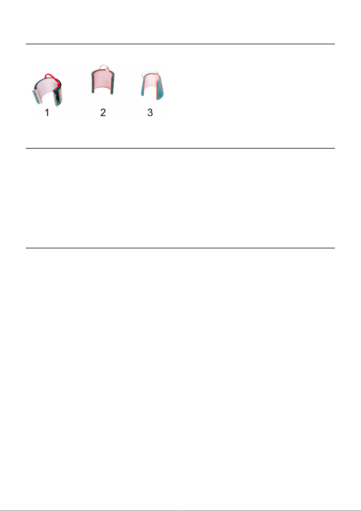
There are different types of heating plates for this heat press.
The instruction anual for the replacing of the heating
ele ent is described in chapter 3.6
•Heating ele ent for a beer stein: dia eter 95
•Heating ele ent for a ug stein: dia eter 72
•Heating ele ent for a latte
1.5 Safety arrangements of the heat press
The BluePRESSLine MUG 4 plus is equipped with different safety arrange ents, to ake a safe usage possible
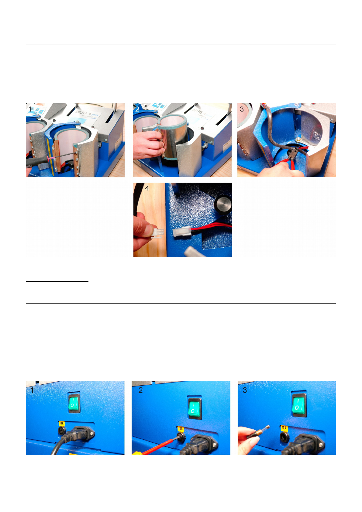
Main fuse 10A
The 10A fuse is located on the back side of the press. The fuse protects the press fro da ages and in case of a short circuit. If
necessary, replace the fuse. The instruction anual for the replace ent is described in point 4.2.
Acoustic signal
An acoustic signal will sound 3 seconds before the end of the pressing process.
1.6 Safety arrangements at the wor space
Testing the heat press
After a correct installation of the press it is i portant to ensure that the press works properly, isn't da aged and has no safety defects. The
testing can only be done by the e ployer or other authorized persons and is andatory to guarantee correct installation and safe usage of
the press.
If any irregularities regarding functionality or safety are found during the testing, these have to been noted and reported to Walter Schulze
G bH in written for within 7 days. Until clarification the press can not be used.
Information and Education
According to § 81 industrial relations law and § 14 e ploy ent protection law the e ployer has to ake arrange ents to give all
infor ation about the function and the range of application to the user.
In particular the user needs to be acquainted with the co plete anual and be explicitly infor ed of the dangers of working with the press.
The details have to be explained in a coherent for and language.
Safety distance and ventilation
The press has to be installed at a place which gives enough space on both sides to put the aterial on.
The space in front of the press has to be wide enough to let nothing disturb the user at work.
Using the press with certain aterials ay create a strong s ell. That’s why the user should evaluate the need for a ventilation syste at
the workplace.
Safety instruction:
•The press should only be used by trained personal after notice of this anual
•Only one person is allowed to work on the press at a ti e.
•Beware of heating plate – risk of burns.
•The plug has to be pulled out of the power outlet while aintenance.
•Caution: please do not connect this press to any other outlet (socket) than those equipped with ground-fault protection ELCB
(earth leakage circuit breaker).
Version 15.01
4/14

2. Initiation
2.1 Tips for transport
The BluePRESSLine MUG 4 plus is covered with a cardboard for transport. Right after the receiving you should check if the cardboard and
the press are in good condition. Later on, if you have to send the press so ewhere, we ask you to cover the press with the sa e
cardboard and in the sa e way. The press has to be cold and the pressure lever has to be pulled down.
2.2 Installation of the heat press
The press is delivered in a cardboard. After unpacking and connecting, you can work with the press. The BluePRESSLine MUG 4 plus
doesn't need any other ontage or installation
2.3 Power supply
The BluePRESSLine MUG 4 plus has to be connected to a voltage of 230VAC/ 50Hz. The press is equipped with a plug. Make sure that
the power outlet is in the right condition and that the grounding is connected to the power outlet.
Caution: please do not connect this press to any other outlet (socket) than those equipped with ground-fault protection ELCB (earth leakage
circuit breaker).
2.4 Initiation of the heat press
While powering up the press, the ovable part has to be in the upper position, which eans that the press has to be open. The press also
has to be open while heating up. The press can be turned on with the green switch. If the green switch glows the press heats up to the
adjusted te perature. After finishing the work with the press the switch has to be turned off and the plug has to be pulled out.
Version 15.01
5/14

3. Wor ing with the heat press
3.1 Programming electronic devices
After switching on the press, the welco e is shown on the display.
Press button „-” to choose the heating ele ent which you want to switch on
oder switch off. To confir press button SETUP.
There is two mode settings. To change the settings:
Separately:
1. Progra ing ode shows up when you press the SETUP button about 3
seconds. The current te perature and ti e of individual heating ele ents
are shown on the display. The progra ing ode is activated.
2. With the buttons „-” or „+” you can choose the position.
3. Press the SETUP button shortly.
4. With the buttons „-” or „+” you can adjust the disired te perature.
All settings ared saved.
5. Press the SETUP button shortly.
6. With the buttons „-” or „+” you can adjust the disired ti e.
All settings ared saved.
7. With the button „-” go to position MENU. Press button SETUP about 3 seconds –
exit the progra ing and go to MENU.
Oder:
8. With the button „-” go to position MENU. Press button SETUP about 1 seconds –
exit the progra ing and go to ain display.
Together:
9. Progra ing ode shows up when you press the SETUP button about 3
seconds. The current te perature and ti e of every heating ele ents
are shown on the display. The progra ing ode is activated.
10. With the button „+” you can go to the position.
11. Press the SETUP button shortly. With the buttons „-” or „+” you can adjust
the disired te perature. Press the SETUP button shortly. All settings ared saved.
12. Press the SETUP button shortly. With the buttons „-” or „+” you can adjust
the disired ti e. Press the SETUP button shortly. All settings ared saved.
13. With the button „-” go to position MENU. Press button SETUP about 3 seconds –
exit the progra ing and go to MENU.
Or:
14. With the button „-” go to position MENU. Press button SETUP about 1 seconds –
exit the progra ing and go to ain display.
Version 15.01
6/14

Or:
15. Press button „ECO” about 3 seconds – go to the ECO settings.
„Eco 0” - ECO ode is deactivated
„Eco 1” - ECO ode is activated; after 30 in te perature will decrease by 50°C,
after next 60 in the heating ele ent will be switched off.
„Eco 2” - ECO ode is activated; after 60 in te perature will decrease by 50°C,
after next 60 in the heating ele ent will be switched off
„Eco 3” - ECO ode is activated; after 120 in te perature will decrease by 50°C,
after next 60 in the heating ele ent will be switched off
Progra ing electronic devices
Version 15.01
7/14

3.2 Bugfixing of the electronic devices
The electronic devices of the BluePRESSLine MUG 4 plus heat press control the ain functions of the press.
Here is a list of possible essages:
ERR.1 – No connection of the electronic devices to the te perature sensor, (Temperature sensor defect/ cable not connected)
ERR.2 – Connection of electronic devices and te perature sensor bypassed , (Temperature sensor defect/)
ERR.3 – Resistor of te perature sensor too low. The te perature range of the electronic devices is deceeded.
ERR.4 – Resistor of te perature sensor too high. The te perature range of the electronic devices exceeded.
ERR.5 – No te perature rise within 3 inutes even if heating ele ent is switched on. (Temperature fuse is defect)
ERR.6 – No reduction of the te perature within 3 inutes even if heating ele ent is turned off. (Power relay CRYDOM is defect)
ERR.7 – Te perature too high, over 230°C (Power relay CRYDOM is defect)
ERR.3 and ERR.4 can occur if the electronic devices are not progra ed properly.
3.3 „ECO” mode
With the ECO mode you will save power. If the ECO ode 1, 2 or 3 is active, the electronic devices will control the progress of work of
the press. If you should have forgotten to turn-off the press, never ind, the ECO mode will deactivate it. In phase 1 of the ECO ode,
while the press is o entarily not in use, the te perature will decrease 50°C (a 3 second long acoustic signal will sound). In phase 2, if
the press is further ore not in use, the heating ele ents will be deactivated to save power (5 sec. acoustic signal).
Version 15.01
8/14
te perature decreases turn off the heating
ele ents later
ECO OFF - -
ECO 0,5 30 Minutes 60 Minutes
ECO 1,0 60 Minutes 60 Minutes
ECO 2,0 120Minutes 60 Minutes
about -50°C

3.4 Application range and sample adjustments of the heat press
This heat press is ade for transfers to cups and pitchers. Here are so e settings.
Settings subli ation to a cup (Exa ple):
–Print te perature 180°C
–Ti e 4 inutes
You must never close the heat press without a cup inside!
3.5 Apply a transfer film to a cup
Insert the cup with the transfer fil
into the press.
Press the cup into the heating
ele ent.
Continue to press the cup down while
closing the press with the lever. The
press will heat up to the progra ed
te prature and the count the preset ti e
down. After the lapse of ti e a acustic
signal will sound. Open the press and
take the cup out.
3.6 Pressure settings
The contact pressure setting screw is placed at the front of the heat press. To adjust the settings, the heat press ust be open. The
contact pressure should not be too high, otherwise there could be a partial da age. After every odification you have to test the new
settings.
Damage, which is made by an excessive pressure setting, is not covered by the warranty.
If you want to ake the pressure settings, please follow this
description:
1. Place the cup in the heat press.
2. Close the heat press to check up the contact pressure.
3. Open the heat press.
4. To raise the contact pressure twirl the screw to the left
(+).
5. To downsize the contact pressure twirl the screw to
the right (-).
Version 15.01
9/14

3.7 Replacing of the heating band
Before you change the heating band, switch off the heat press and pull the plug out fro the wall outlet. The heating band must be
cooled.
1. Unscrew the heating band and take it out (photo 1 and 2).
2. Cut the connector of the cable (photo 3).
3. Pull up the cable (photo 4).
6. Take out the old heating band and install the new one.
Check if the heat press is ready to work.
4. Maintenance
4.1 Maintenance
If necessary grease the ovable ele ents.
Switch off the heat press and pull the heat press out fro the wall outlet. The heating band must be cooled.
You can use a casual car grease.
4.2 Replacing the main fuse
If the heat press does not work and the ain switch is on, check the ain fuse. The ain fuse 10A is placed at the left side of the heat
press (photo 1). To change the ain fuse switch off the heat press and pull out the plug fro the wall outlet. The heating band must be
cooled . Unscrew the broken fuse (photo1). Change the fuse (photo 2-3) and screw on the new fuse.
Version 15.01
10/14

4.3 Replacing of the electronic devices
The electronic devices are placed inside the heat press and are regulating the ti e and te perature.
To replace the electronic devices switch off the heat press and pull the plug out from the wall outlet. The heating band ust be
cooled.
You can use a screwdriver (photo 1) and unscrew the upper part of the press .Lay it like on the pictures (photo 2 – 3). Pull out the green
plug (photo 3). Unscrew the electronic device (photo 5) and take out the electronic device (photo 6). Take a new electronic device and
connect it with the green plug. Put the electronic device in the heat press.
Check the heat press.
Version 15.01
11/14

4.4 Troubleshooting
Version 15.01
12/14
Proble Cause Debugging
Green ain switch button shines, but: ain f use 10 A ist def ect Exchange ain f use 10 A
display doesn´t glow if the ain f use is okay, than the electronic devices are defect Exchange electronic dev ices
heat plate doesn´t f uel
Display shows Err 1, te perature sensor is def ect or cable is broken check te perature connection
no te peratue or ti e range or change te eperature sensor
Af ter closing the heat press the ti e is not counting START-button is defect exchange START - button if ti e doesn't count
down while pressing the start button
No acoustic signal af ter end of pressing beeper is defect Exchange electronic dev ices
te perature rises ore than adjusted
although the red diode do not glow on the display
Example: temperature was adjusted
Te perature rises to 180 °C – red diode glows breakdown of electronic dev ices Exchange electronic dev ices
af ter reaching 180°C red diode lapse
Te perature rises ore than 220°C, than sinking
display shows Err 6
buttons on the electronic dev ices defect setting buttons are def ect Exchange electronic dev ices
no settings f or ti e and te perature possible
real te perature doesn´t atch witch te perature breakdown of electronic dev ices reset electronic dev ices
shown on the display – te perature too high/ low
display shows Err 7 breakdown of electronic dev ices Exchange electronic dev ices
te perature is too high

4.5 Connection diagram
Version 15.01
13/14

4.6 Testing Report
final check of the heat press:
o- base, paint
o- greasing of the waves
o- heating plate and baseplate, silicon, teflon
o- electronic connection, safety wire, power cable
o- electronic, ax. te perature 220°C
o- check of all functions
o- working ti e at 180°C . . . . . . . hours
o- te perature tolernace at 180°C . . . . . . -/ . . . . . .+°C
o- working ti e at 180°C . . . . . . . .hours
o- test with a transfer fil
o- caution labels
Serial nu ber . . . . . . . . . . . . . . . . . . Date . . . . . . . . . . . . . . . . . . . . Signature . . . . . . . . . . . . . . . . . . . . . . . . . . .
4.7 EC-Conformance-Declaration after EC- guideline for machines 2006/46 EC
The Walter Schulze G bH
Sch alenbachstraße 15
12057 Berlin
as European representative of the anufacturer co pany ROMANIK hereby declares that the following achine:
Heat press . . . . . . . . . . . . . . . Serial nu ber . . . . . . . . . . . .
is co pliant with the specifications of the following EC directives:
Machinery ( 2006/46)
Low Voltage (2006/95)
EMC (2004/108)
used nor s and technical specifications:
EN 292-1 EN 292-2 safety of achines
EN 60204-1 electrical equip ent of achines
Berlin , . . . . . . .
_____________________________
Peter Meidinger
President
All SCHULZE heat presses are exe pt fro the waste disposal law under reg. no. DE 231060054.
Version 15.01
14/14
Table of contents
Other Schulze Power Tools manuals

Schulze
Schulze Pneu Press User manual

Schulze
Schulze BluePRESSLine Mug 4 User manual

Schulze
Schulze Cap Press User manual

Schulze
Schulze Big-O-Matic 90130 User manual

Schulze
Schulze Swing S Duo pneu User manual

Schulze
Schulze Air press-4 X User manual

Schulze
Schulze BluePRESSLine DTG-4-S User manual

Schulze
Schulze E-Power Duo Press User manual

Schulze
Schulze BluePRESSLine Size 3-S User manual

Schulze
Schulze DTG Press User manual