BURWELL Elcometer 355 User manual

English
Elcometer 355
Coating Thickness Gauge
Standard Model
Operating Instructions
Product Manual
355 Coating Thickness Gauge
For more information: 1300 287 935 / mail@burwell.com.au / www.burwell.com.au
Copyright 2016 Burwell Technologies

English
R
This product meets the Electromagnetic Compatibility Directive. This product is Class B, Group 1
ISM equipment according to CISPR 11 Group 1 ISM product: A product in which there is
intentionally generated and/or used conductively coupled radio-frequency energy which is
necessary for the internal functioning of the equipment itself.
Class B products are suitable for use in domestic establishments and in establishments directly connected
to a low voltage power supply network which supplies buildings used for domestic purposes.
is a registered trademark of Elcometer Limited.
All other trademarks acknowledged.
© Copyright Elcometer Limited. 2009-2011.
All rights reserved. No part of this Document may be reproduced, transmitted, transcribed, stored (in a retrieval
system or otherwise) or translated into any language, in any form or by any means (electronic, mechanical,
magnetic, optical, manual or otherwise) without the prior written permission of Elcometer Limited.
A copy of this Instruction Manual is available for download on our Website via www.elcometer.com.
Doc.No. TMA-0143 Issue 06
Text with Cover No: 4804
355 Coating Thickness Gauge
2 of 48For more information / 1300 287 935 mail@burwell.com.au / www.burwell.com.au

R
1
CONTENTS
Section Page
1 About your gauge . . . . . . . . . . . . . . . . . . . . . . . . . . . . . . . . . . . . . . . . . . . . . . . . . . . . . . . . . . . . . . . . 2
2 Getting started. . . . . . . . . . . . . . . . . . . . . . . . . . . . . . . . . . . . . . . . . . . . . . . . . . . . . . . . . . . . . . . . . . . 5
3 Taking a reading . . . . . . . . . . . . . . . . . . . . . . . . . . . . . . . . . . . . . . . . . . . . . . . . . . . . . . . . . . . . . . . . . 8
4 Calibration - BASE and CAL . . . . . . . . . . . . . . . . . . . . . . . . . . . . . . . . . . . . . . . . . . . . . . . . . . . . . . . 9
5 Batches and memory . . . . . . . . . . . . . . . . . . . . . . . . . . . . . . . . . . . . . . . . . . . . . . . . . . . . . . . . . . . . 10
6 Setup . . . . . . . . . . . . . . . . . . . . . . . . . . . . . . . . . . . . . . . . . . . . . . . . . . . . . . . . . . . . . . . . . . . . . . . . . 12
7 Statistics . . . . . . . . . . . . . . . . . . . . . . . . . . . . . . . . . . . . . . . . . . . . . . . . . . . . . . . . . . . . . . . . . . . . . . 21
8 Transferring readings to a computer . . . . . . . . . . . . . . . . . . . . . . . . . . . . . . . . . . . . . . . . . . . . . . . 22
9 Printing. . . . . . . . . . . . . . . . . . . . . . . . . . . . . . . . . . . . . . . . . . . . . . . . . . . . . . . . . . . . . . . . . . . . . . . . 23
10 Fault Finding / Error Codes . . . . . . . . . . . . . . . . . . . . . . . . . . . . . . . . . . . . . . . . . . . . . . . . . . . . . . . 27
11 Storage. . . . . . . . . . . . . . . . . . . . . . . . . . . . . . . . . . . . . . . . . . . . . . . . . . . . . . . . . . . . . . . . . . . . . . . . 29
12 Maintenance . . . . . . . . . . . . . . . . . . . . . . . . . . . . . . . . . . . . . . . . . . . . . . . . . . . . . . . . . . . . . . . . . . . 29
13 Accessories . . . . . . . . . . . . . . . . . . . . . . . . . . . . . . . . . . . . . . . . . . . . . . . . . . . . . . . . . . . . . . . . . . . . 30
14 Technical Specification . . . . . . . . . . . . . . . . . . . . . . . . . . . . . . . . . . . . . . . . . . . . . . . . . . . . . . . . . . 35
15 Related equipment . . . . . . . . . . . . . . . . . . . . . . . . . . . . . . . . . . . . . . . . . . . . . . . . . . . . . . . . . . . . . . 35
16 Tutorial . . . . . . . . . . . . . . . . . . . . . . . . . . . . . . . . . . . . . . . . . . . . . . . . . . . . . . . . . . . . . . . . . . . . . . . . 36
17 Quick Reference Guide. . . . . . . . . . . . . . . . . . . . . . . . . . . . . . . . . . . . . . . . . . . . . . . . . . . . . . . . . . . 42
355 Coating Thickness Gauge
3 of 48For more information / 1300 287 935 mail@burwell.com.au / www.burwell.com.au

R
2
Thank you for your purchase of this Elcometer 355 Coating Thickness Gauge. Welcome to Elcometer.
Elcometer are world leaders in the design, manufacture and supply of coatings inspection equipment. Our
products cover all aspects of coating inspection, from development through application to post application
inspection.
The Elcometer 355 Coating Thickness Gauge is a world beating product. With the purchase of this gauge
you now have access to the worldwide service and support network of Elcometer. For more information visit
our website at www.elcometer.com
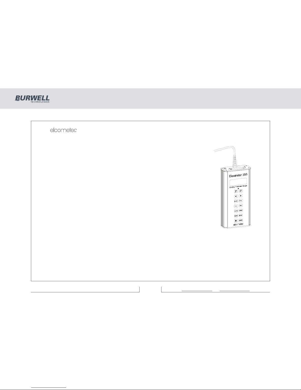
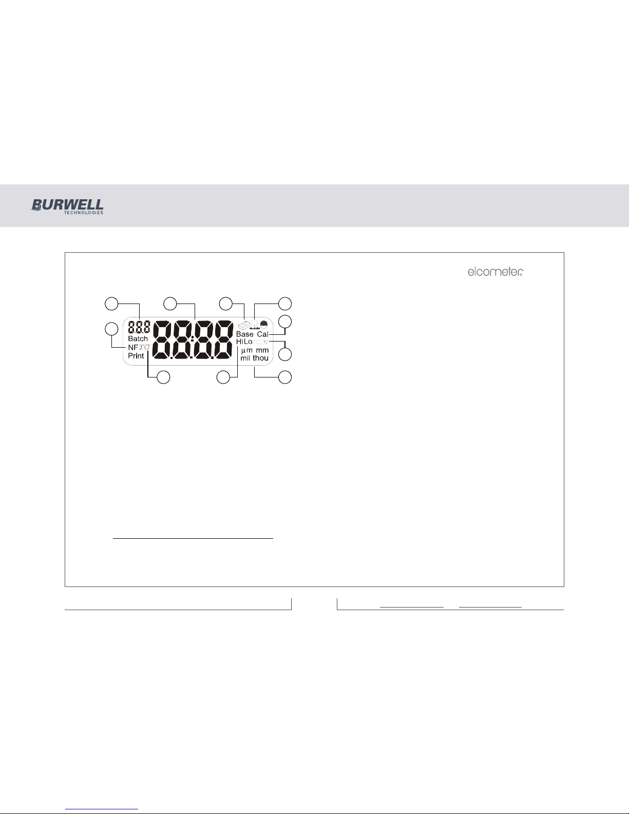
1 ABOUT YOUR GAUGE
The Elcometer 355 Coating Thickness Gauge is a handheld gauge for fast and accurate measurement of
the thickness of coatings.
With a memory of up to 5000 readings in multiple batches and accuracy to ±1%, your gauge is a measuring
system packed with time saving and cost cutting features.
1.1 STANDARDS
The Elcometer 355 can be used in accordance with the following National and International Standards:
FERROUS (F)
ASTM B 499, ASTM D 1186-B, ASTM G 12, BS 3900(C5), BS 5411 (11), DIN 50981, IMO MSC.215 (82),
IMO MSC.244(83), ISO 1461, ISO 2063, ISO 2808-7C, supersedes ISO 2808-6A, BS 3900-C5-6A, BS
5411-11, DIN 50981, ISO 2808-12, ISO 19840, NF T30-124, SSPC-PA2.
355 Coating Thickness Gauge
4 of 48For more information / 1300 287 935 mail@burwell.com.au / www.burwell.com.au

R
3
For the IMO PSPCa, the thickness of coatings should be recorded. Your Elcometer 355 can be used for this.
NON-FERROUS (NF)
ASTM D 1400, BS 3900 (C5), BS 5411 (3), BS 5599, DIN 50984, ISO 2360 supersedes BS 5411-3,
ISO 2808-7D supersedes BS 3900-C5-6B, BS 5411-3, DIN 50984, ISO 2808-6B, ISO 2808-12,
ASTM B244 (probes N1, N4).
FERROUS AND NON-FERROUS (FNF)
AS 2331.1.4, AS 3894.3-B, AS/NZS 1580.108.1, ASTM D 7091 supersedes ASTM D 1186, ASTM D 1400,
ASTM E 376, EN 13523-1 supersedes ECCA T1, ISO 2808-12, US NAVY NSI 009-32,
US NAVY PPI 63101-000.
a. International Marine Organisation, Performance Standard for Protective Coatings.
355 Coating Thickness Gauge
5 of 48For more information / 1300 287 935 mail@burwell.com.au / www.burwell.com.au

R
4
1.2 WHAT THE BOX CONTAINS
• Elcometer 355 Standard Gauge
• Leather carry case
• Precision Hand Grip
• Earpiece
• CD containing data collection software
• PC Cable
• Batteries
• Operating instructions
The gauge is packed in cardboard and foam packaging. Please ensure that this
packaging is disposed of in an environmentally sensitive manner. Consult your Local
Environmental Authority for further guidance.
To maximise the benefits of your new Elcometer 355, please take some time to
read these Operating Instructions.
Do not hesitate to contact Elcometer or your Elcometer supplier if you have any
questions.
355 Coating Thickness Gauge
6 of 48For more information / 1300 287 935 mail@burwell.com.au / www.burwell.com.au

R
5
2 GETTING STARTED
2.1 REMOVING THE CASE
To remove the leather case to gain access to the module and
battery compartments, undo the retaining screw located on the
bottom of the case and remove the gauge by pushing it through
the hole.
2.2 FITTING BATTERIES
Batteries are located under the cover at the rear of the gauge.
Fit three LR6 (AA), alkaline dry batteries, or rechargeable
equivalent; take care to ensure correct battery polarity.
When the battery symbol is shown on the display, the
batteries should be replaced. When the symbol starts flashing,
the batteries will last approximately one more hour.
Note: Remove the batteries from the instrument if it is to remain
unused for a long period of time. This will prevent damage to the
instrument in the event of malfunction of the batteries.
Note: All batteries must be disposed of carefully to avoid
environmental contamination. Please consult your local
Environmental Authority for information on disposal in your
region.
Do not dispose of any batteries in fire.
(Elcometer 355
Top model shown)
355 Coating Thickness Gauge
7 of 48For more information / 1300 287 935 mail@burwell.com.au / www.burwell.com.au

R
6
2.3 CONNECTING A PROBE MODULE
1. Ensure the probe is suitable for the measurements to be made.
2. Switch off the gauge.
3. Open the cover at the back of the gauge.
4. Insert the probe module.
5. Replace the cover.
2.4 SWITCHING THE GAUGE ON AND OFF
• To switch your gauge on, press and hold [ ].
The red LED flashes, the gauge clicks and all segments of the display are illuminated with the
backlight on. The Software Version Number is then displayed.
The instrument will then start up in the mode last used.
Completion of start-up is indicated by one long beep and the red LED flashing.
• To switch your gauge off, press and hold [ENTER] for three seconds.
Your gauge can also be set to switch off automatically - see “Date and time” on page 14.
355 Coating Thickness Gauge
8 of 48For more information / 1300 287 935 mail@burwell.com.au / www.burwell.com.au

R
7
2.5 THE DISPLAY
1. Reading number
2. Reading/menu item/value
3. Service required
4. Rough surface
5. Calibration type
6. Battery condition
7. Units
8. Limits
9. Average/Standard deviation
10. Non-ferrous/Ferrous
2.6 INTERFACE
A data output interface is located on the top of your gauge.
2.7 SELECTING A LANGUAGE
The Elcometer 355 has a number of languages built-in.To select a language, see “Language function” on page 17.
2.8 CHANGING UNITS
Your gauge can display coating thickness in µmb(microns), mm, mil and thou.
To change units, press [UNITS].
Note: When units are set to mm, the resolution of the display is such that only 1 µm resolution may be
shown, e.g. 10.8 µm would be displayed as ‘0.011’ mm.
b. µm will not be available as an option on probes which have a range greater than 9999 µm
1 3 4
5
6
789
10
2
355 Coating Thickness Gauge
9 of 48For more information / 1300 287 935 mail@burwell.com.au / www.burwell.com.au

R
8
3 TAKING A READING
Switch on the gauge.
Place the probe on the surface to be measured. The reading may be
inaccurate if the probe is not held as shown.
The green LED will flash and a beep will sound when a valid reading has been
taken.
The coating thickness is shown on the display.
If the reading is just above the range of the module, the display shows:
In certain base conditions a negative over range can occur, indicated by:
In either of these two cases, check and re-calibrate if necessary - see “Calibration
- BASE and CAL” on page 9.
In some conditions, the display may show error codes ‘E14’, ‘E15’, etc. For
details of these error codes, see “Fault Finding / Error Codes” on page 27.
To save readings into memory (batching), refer to the instructions given in
“Batches and memory” on page 10.
R
355 Coating Thickness Gauge
10 of 48For more information / 1300 287 935 mail@burwell.com.au / www.burwell.com.au

R
9
4 CALIBRATION - BASE AND CAL
1. Press [BASE] for low end calibration on a zero plate or low value foil and [CAL] for higher foil.
2. Take a number of readings on the required calibration thickness. (Uncoated material for zero or base,
a thin foil for rough surface or unusual materials and a thick foil for cal).
(A wide range of foils is available - see “Foils” on page 32.)
The foil value shown on the label applies to a measurement position
as indicated:
The display will show an average value - indicated by the [ ]
symbol.
3. When the base or cal value shown on the display is stable, then
adjust the display to the required value e.g. ‘0’ or the foil value; use
the [>] (CalUp) or [<] (CalDown) keys to adjust the value and then
press [ENTER].
The ‘base’ or ‘cal’ symbols and [ ] will now be removed from the display.
If a base value greater than zero is entered, the rough surface symbol will be displayed.
This symbol will disappear from the display if the base is reset to zero (0).
Note: If ‘base’ or ‘cal’ are used with regular values, the [BASE] or [CAL] keys may be pressed to recall the
last value entered to the display in order to save re-entering the numeric data. [ENTER] is used to confirm
the display value in memory.
355 Coating Thickness Gauge
11 of 48For more information / 1300 287 935 mail@burwell.com.au / www.burwell.com.au

R
10
5 BATCHES AND MEMORY
5.1 SELECTING A BATCH
Batch numbers between 1 and 25 can be selected as follows.
With the instrument switched on, press [SETUP]. The display will show:
If a batch is selected the batch symbol is on.
This signifies the Auto Batch Entry Menu.
Press [ENTER].
An indication of the remaining memory will be displayed:
Bars will be removed from this display as the memory is filled. The upper bars
show approximately 11% increments and the lower bars approximately 1%
increments.
If the batch is new, the display will be blank and ‘0’ will be shown as the reading
no:
Batch numbers from 1 to 25 are preset and can be shown in the display by
pressing [<] or [>] until the batch number required is visible.
When the correct batch number is displayed, press [ENTER] to load this batch in
Auto batch mode.
If data exists in the batch selected, the last reading will be displayed.
355 Coating Thickness Gauge
12 of 48For more information / 1300 287 935 mail@burwell.com.au / www.burwell.com.au

R
11
or, if it is a new batch, then ‘0’ is displayed as a reading number and the reading
display is blank.
If the existing batch has been created with a different module to the one currently
connected, the display shows ‘E14’.
Immediate mode is designated as ‘BATCH 0’. Returning to immediate mode from batch mode clears all
previous immediate mode data and starts at reading ‘0’.
5.2 CLEAR/DELETE BATCH DATA
Data within a batch may be ‘cleared’ leaving the probe type and calibration. Alternatively the batch data and
its associated probe type and calibration may be ‘deleted’.
CLEARING BATCH DATA
Select the batch to be cleared - see “Selecting a batch” on page 10
Press [CLEAR] and the display will alternate between ‘Clr’ and ‘batch no’ as
shown (batch number 14 in this example).
Press [ENTER] to clear the selected batch. If ‘Batch 0’ is selected and [CLEAR] is
pressed, then all batches may be cleared and the display will alternate as shown:
355 Coating Thickness Gauge
13 of 48For more information / 1300 287 935 mail@burwell.com.au / www.burwell.com.au

R
12
alternating with
Press [ENTER] to clear all batches, or [Esc] to cancel the operation. Press [Esc]
again to return to immediate mode.
DELETING BATCH DATA
Select the batch to be deleted - see “Selecting a batch” on page 10.
Press [DEL] and the display will alternate between ‘dEL’ and ‘batch no’ as shown
(batch number 14 in this example).
Press [ENTER] to delete the selected batch or [Esc] to cancel the operation.
If ‘Batch 0’ is selected and [DEL] is pressed, then all batches may be deleted and
the display will alternate between ‘dEL’ and ‘ALL?’
Press [ENTER] to delete all batches or [Esc] to stop the operation.
6 SETUP
The setup mode enables the User to adjust a number of different functions to suit the way the instrument is
operated. The setup mode is based around 10 functions, each of which has sub-functions.
After pressing [SETUP], Function No 10 (for auto batching mode) will be
displayed:
355 Coating Thickness Gauge
14 of 48For more information / 1300 287 935 mail@burwell.com.au / www.burwell.com.au

R
13
Other functions may be selected by using [<] or [>] to go through the list. If [<] or [>] are pressed the
individual functions are displayed and [ENTER] must then be pressed to select that function for modification.
The symbol ‘nA’ in the display indicates that the function is not available in the Standard version of software.
Once a function is entered, [<] or [>] are used to either select the alternatives, or modify the value.
Sub-functions are displayed using a second number in the ‘n’ display. e.g. ‘11’ for baud function within ‘Prnt’.
Select the required value for the function or sub-function by pressing [ENTER]. Exit the function by pressing
[SETUP] the required number of times (or [Esc]) to step back through the Sub Menus.
This display signifies the end of each menu’s options.
The following sections describe each function (in numerical order).
6.1 PRINTER SETUP FUNCTIONS
Having pressed [SETUP] use [<] or [>] to select:
Press [ENTER].
Printer SetUp Sub-Functions
For serial printing, the printer’s baud rate must be selected in the range 300-
38,400.
Press [ENTER] and use [<] or [>] to select one of the options which are available
e.g.
Press [ENTER] to set this option to required rate and return to the Printer SetUp
Menu, or [Esc] to cancel the operation.
355 Coating Thickness Gauge
15 of 48For more information / 1300 287 935 mail@burwell.com.au / www.burwell.com.au

R
14
Continue stepping through the Printer SetUp Menu by using [>]. Press [ENTER] at the required option and
use [<] and [>] to select within that option ([Esc] cancels the operation):
End of line character is Cr or CrLF.
Selects 80 or 42 column printing (42 col. for Elcometer Portable Printer).
Page length 0-100 lines (0 for continuous printing).
0-10 spaces of indentation from left (not available with 42 column printer).
Type of report: Full or PArt (no readings).
6.2 DATE AND TIME
When setting the date and time, the display flashes a 2 digit pair for day, month, hours or minutes. These
may be adjusted up or down by using [<] and [>] respectively. The year is a 4 digit number with limits of
1994 and 2093 and is adjusted using the [<] and [>] keys as before.
Having pressed [SETUP], use [<] or [>] to select, followed by [ENTER]:
Date and Time Sub Functions.
355 Coating Thickness Gauge
16 of 48For more information / 1300 287 935 mail@burwell.com.au / www.burwell.com.au

R
15
Use [<] or [>] to select any of the following five sub functions:
Date format by Country
There are two date formats available:
or
d:M for Day:Month (UK)
M:d for Month:Day (USA)
Press [ENTER] or [Esc] to return to the ‘Coun’ display.
Continue stepping through the time and date functions by using [>]. Press [ENTER] at the required option
and use [<] and [>] to select within that option ([Esc] cancels the operation):
Set day/month and year).
Set time of day.
Time stamp (not available on Elcometer 355 model Standard).
Switch off timeout period in minutes (1-30) or 0 for none.
355 Coating Thickness Gauge
17 of 48For more information / 1300 287 935 mail@burwell.com.au / www.burwell.com.au

R
16
6.3 BEEPER FUNCTION
Having pressed [SETUP], use [<] or [>] to select:
Press [ENTER], and set beeper volume level using [<] or [>] (1 - 4 or 0 for none).
Press [ENTER] to return to the ‘bEEP’ display or [Esc] to cancel the operation.
6.4 PASSWORD FUNCTION
Having pressed [SETUP], use [<] or [>] to select:
Password Function
(not available on Elcometer 355 model Standard)
6.5 AUTO MEASUREMENT MODE FUNCTION
Having pressed [SETUP], [<] or [>] selects:
This mode takes readings automatically and displays them digitally in the chosen
units giving a form of analogue display. Press [ENTER] and use [<] and [>] to
toggle between:
no - Normal digital Coating Thickness mode.
YES - Produces readings automatically.
The beeper should be turned off to stop it sounding continuously. Press [ENTER] to set this option or [Esc]
to cancel the operation.
355 Coating Thickness Gauge
18 of 48For more information / 1300 287 935 mail@burwell.com.au / www.burwell.com.au

R
17
6.6 BATTERY FUNCTION
Having pressed [SETUP], use [<] or [>] to select:
Press [ENTER] to show the battery level as a number of units. New alkaline
batteries should display approximately 220 units. New Rechargeable batteries
should display approximately 180 units. All batteries need to be replaced at
readings of approximately 145. Note that Elcometer supplied rechargeable batteries should give a life of
1hr. between a flashing and a constant battery symbol, but alkaline batteries should last for a number of
hours.
Press any operations key to return to the ‘bAtt’ display.
6.7 BACKLIGHT FUNCTION
Having pressed [SETUP], use [<] or [>] to select:
Backlight Enable/Disable.
Press [ENTER] and use [<] and [>] to toggle between:
on - Ensures the backlight is on at all times when required, but timed to maximise battery life.
oFF - The backlight will be off at all times except for power up display test.
Press [ENTER] to set this option or [Esc] to cancel the operation.
6.8 LANGUAGE FUNCTION
Having pressed [SETUP], use [<] or [>] to select:
Language formats used on printouts.
Press [ENTER] to see which language version is active.
355 Coating Thickness Gauge
19 of 48For more information / 1300 287 935 mail@burwell.com.au / www.burwell.com.au

R
18
The following languages are available:
English German
French Portuguese
Swedish Danish
Press [SETUP], [ENTER] or [Esc] to return to the ‘LAn’
display.
6.9 REASONABLE LIMITS FUNCTION
Not available with standard software.
The ‘nA’ message will be displayed and the Elcometer 355 then exits the SetUp
Menu automatically.
6.10 AUTOBATCH
This signifies the Autobatch entry Menu.
Note: If a batch is selected the batch symbol is on.
Pressing [ENTER] will consecutively display the following information:
This display shows the memory level for approximately 1 second.
355 Coating Thickness Gauge
20 of 48For more information / 1300 287 935 mail@burwell.com.au / www.burwell.com.au
Table of contents
Other BURWELL Measuring Instrument manuals