ProfessionalLINE
6828 Funkmodul
Umweltschäden
■ Verbrauchte Batterien nicht mit dem Hausmüll
entsorgen.
■ Defekte Lithium-Batterien nicht per Luftfracht
verschicken. Bei anderen Transportarten die
Sondervorschrift 188 der ADR beachten.
■ Anleitung sorgfältig lesen und aufbewahren.
■ Weitere Benutzerinformationen und Informationen zur Planung
unter www.BUSCH-JAEGER.de oder durch Scannen des
QR-Codes.
Bestimmungsgemäßer Gebrauch
Das Funkmodul dient der drahtlosen Vernetzung von bis zu 20
Busch-Rauchalarm® /-Wärmealarm-Produkten.
Löst ein funkvernetzter Melder Alarm aus, sendet das Funkmodul
entsprechende Daten an alle mit ihm vernetzten Geräte
EU-Konformitätserklärung (vereinfacht)
Hiermit erklärt Busch-Jaeger, dass das Funkmodul 6828 der
Richtlinie 2014/53/EU entspricht. Der vollständige Text der EU-
Konformitätserklärung ist unter der folgenden Internetadresse
verfügbar:
Technische Daten
Stromversorgung
(fest eingebaute Lithium-Batterie): 2.000 mA/h
Batterielebensdauer (Jahre): >10
Funkfrequenz: 868 MHz
Funkreichweite, max.: 100 m
Max. Anzahl der vernetzten Geräte: 20
Betriebstemperatur: 0 °C … +40 °
Lagertemperatur: -10 °C … +60 °C
Standards: DIN EN 14604, Din 14676
Zulassung: VdS G208016
Produktbeschreibung
Funkmodul:
[A] Funkmodul
[B] Antenne
[C] LED (rot)
[D] Codierknopf
[E] LED (blau)
Sichtbar auf der Vorderseite des Melders. Zeigt durch blaues
Aufleuchten Funksignale an (leuchtet sehr schwach durch das
Gehäuse).
Melder (nicht im Lieferumfang):
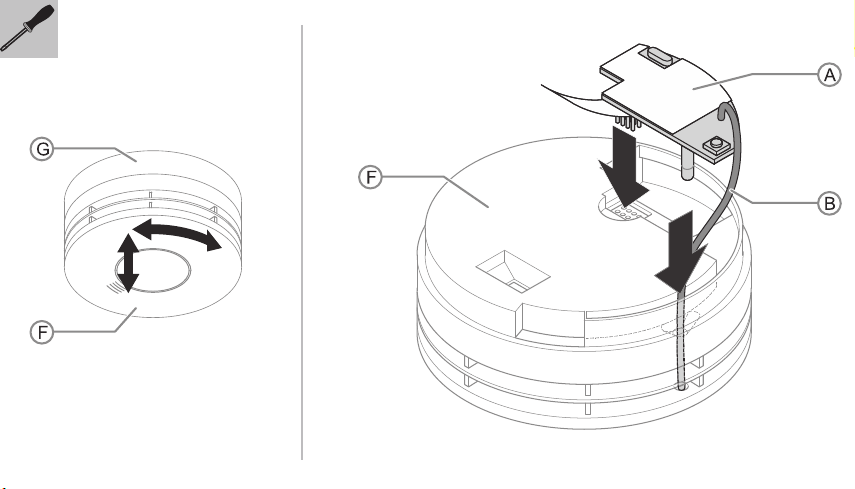
[F] Melder
[G] Montageplatte
[H] LED (rot) des Melders
[I] Testknopf (löst den Alarmton aus)
Montage
1. Melder [F] aus der Montageplatte [G] entnehmen.
– Der Melder ist mit einem Bajonettverschluss eingesetzt.
2. Funkmodul [A] in die Aussparung im Melder [F] einstecken.
– Auf korrekten Steckerkontakt und die richtige Verlegung des
Antennendrahts [B] im Meldergehäuse achten.
Codierung / Funkvernetzung
■ Vor Beginn der Codierung sicherstellen, dass alle Funkmodule in
die Melder eingelegt sind.
■ Die Funkvernetzung der Melder wird über die Aktivierung des
Codiermodus durchgeführt.
Codiermodus aktivieren:
1. Codierknopf [D] des Funkmoduls drücken und gedrückt halten,
bis die LED [C] auf dem Funkmodul rot aufleuchtet.
– Sobald sie leuchtet, den Codierknopf [D] loslassen. Die
LED [C] blinkt anschließend mehrmals schnell hintereinander.
Dies zeigt an, dass sich das Funkmodul in der Codierung
befindet.
2. Melder in die Montageplatte einsetzen.
– Der Melder ist mit einem Bajonettverschluss versehen.
– Durch das Einsetzen werden die Codierung und damit die
Suche nach weiteren Meldern für 30 Minuten aktiviert.
– Beim Einsetzen des Melders in die Montageplatte leuchtet die
rote LED [H] des Melders einmal kurz auf.
3. Alle übrigen Melder ebenfalls in den Codiermodus versetzen und
innerhalb der 30 Minuten auf die gleiche Weise in die
Montageplatten einsetzen.
Die Melder bleiben für 30 Minuten im Codiermodus, bevor sie diesen
automatisch verlassen.
Die Vernetzung (Codiermodus) überprüfen
Die Vernetzung wird über die blaue LED [E] angezeigt.
– Die blaue LED [E] leuchtet nur sehr schwach durch den Melder
hindurch. Die Überprüfung am besten im Dunkeln durchführen.
– Es kann bis zu 30 Sekunden dauern, bis die LED [E] eines
Melders leuchtet. In dieser Zeit sucht der Melder weitere
Funkkomponenten.
Die blaue LED [E] zeigt an:
■ Dass der Melder im Codiermodus ist.
■ Wie viele Melder erkannt wurden, die „gelernt“ haben, dass sie
Teil des Systems sind.
Beispiel: Bei 3 Meldern im System leuchtet die LED [E] alle
5 Sekunden dreimal kurz blau auf.
– Sicherstellen, dass die Anzahl der blauen Leuchtzeichen mit der
Anzahl der Melder im System übereinstimmt.
Codiermodus manuell beenden (beendet den Codiermodus der
gesamten vernetzten Gruppe):
■ Einen Melder von der Montageplatte entfernen und den
Codierknopf [D] drücken.
– Den Codierknopf [D] solange gedrückt halten, bis die LED [C]
auf dem Funkmodul rot aufleuchtet. Sobald die LED [C]
leuchtet, den Codierknopf [D] loslassen. Die LED [C] leuchtet
anschließend dauerhaft auf. Das Funkmodul hat nun die
Codierung beendet und sendet ebenfalls ein Signal in die
vernetzte Gruppe, um die Codierung des ganzen Systems zu
beenden.
■ Melder wieder auf der Montageplatte anbringen.
– Die LED [E] hört auf blau zu blinken.
■ Überprüfen, das die LEDs [E] an den anderen Meldern aufgehört
haben blau zu blinken.
Funkvernetzung testen
■ Alle Melder der Reihe nach per Knopf [I] testen.
– Mit dem Druck auf den Knopf wird der Alarmton aktiviert.
– Überprüfen, das dabei alle Melder zur selben Zeit Alarm
geben.
– Die Überprüfungen in Abständen von je ca. 5 Minuten
durchführen, damit die Geräte alle Funksignale abarbeiten
können.
Codierung löschen
■ Den Codierknopf [D] drücken und halten, bis die LED [C] einmal
blinkt.
■ Anschließend den Codierknopf [D] loslassen. Die LED [C] wir nun
noch einmal rot aufleuchten, um anzuzeigen, dass die Codierung
gelöscht wurde.
Funkmodul auf Werkseinstellungen zurücksetzen
Das Funkmodul wird auf seine ursprüngliche Werkseinstellung
zurückgesetzt, indem der Codierknopf gedrückt bleibt, bis die rote
LED [C] dauerhaft leuchtet und anschließend langsam blinkt. Dieser
Vorgang dauert ca. 10 Sekunden. Dadurch werden die erlernten
Hauscodierungen gelöscht.
Service
Busch-Jaeger Elektro GmbH - Ein Unternehmen der ABB Gruppe,
Freisenbergstraße 2, D-58513 Lüdenscheid,
Tel.: +49 2351 956-1600;
www.BUSCH-JAEGER.de
English
Busch-Smoke alarm detector
ProfessionalLINE® ProfessionalLINE
6828 Radio module
Environmental damage
■ Do not dispose of used batteries in the household
waste.
■ Defective lithium batteries must not be sent via air
freight. For other types of transport the special
regulation 188 of the ADR must be adhered to.
■ Please read the instruction manual carefully and retain it for future
use.
■ Additional user information and information about planning is
available at www.BUSCH-JAEGER.de or by scanning the QR
code.
Intended use
The radio module serves for the wireless connection of up to 20
Busch-Smoke alarm detector ProfessionalLINE®/heat alarm products.
If a radio-networked detector triggers an alarm, the radio module
sends the corresponding data to all devices it is connected to.
EU declaration of conformity (simplified)
Busch-Jaeger herewith declares, that radio system type Radio
module 6828 conforms to directive 2014/53/EU. The complete text of
the EU declaration of conformity is available at the following Internet
address:
Technical Data
Power supply
(permanently installed lithium
battery):
2,000 mA/h
Battery service life (years): >10
Radio frequency: 868 MHz
Maximum radio range: 100 m
Maximum number of networked
devices: 20
Operating temperature: 0°C to +40°C
Storage temperature: -10°C to +60°C
Standards: DIN EN 14604, DIN 14676
Certification: VdS G208016
Product description
Radio module:
[A] Radio module
[B] Antenna
[C] LED (red)
[D] Coding button
[E] LED (blue)
Visible on the front of the detector. Lights up blue to show radio
signals (lights up very weak through the housing).
Detector (not included in scope of delivery):
[F] Detector
[G] Mounting plate
[H] LED (red) of the detector
[I] Test button (triggers the alarm tone)
Mounting
1. Remove the detector [F] from the mounting plate [G].
– The detector is inserted with a bayonet joint.
2. Insert the radio module [A] into the recess of the detector [F].
– Ensure that the plug contact is correct and the antenna cable
[B] is installed correctly in the detector housing.
Coding / radio network
■ Before the start of coding ensure that all radio modules have been
inserted into the detectors.
■ The radio networking of the detectors is carried out via the
activation of the coding mode.
Activating the coding mode:
1. Press the coding button [D] of the radio module and keep it
pressed until the LED [C] on the radio module lights up red.
– Release the coding button [D] as soon as the LED lights up.
The LED [C] will then quickly flash consecutively several
times. This indicates that the radio module is now in coding
mode.
2. Insert the detector into the mounting plate.
– The detector is equipped with a bayonet joint.
– The insertion activates the coding and the search for
additional detectors for 30 minutes.
– When inserting the detector into the mounting plate, the red
LED [H] of the detector briefly lights up just once.
3. Set all the remaining detectors into the coding mode and insert
them into the mounting plates in the same manner within 30
minutes.
The detectors remain in coding mode for 30 minutes before exiting it
automatically.
Checking the networking (coding mode)
The networking is displayed via the blue LED [E].
– The blue LED [E] lights up rather weakly through the detector.
The check is best carried out in the dark.
– It can take up to 30 seconds before the LED [E] of the detector
lights up. During this time the detector searches for additional
radio components.
The blue LED [E] indicates:
■ That the detector is in coding mode,
■ How many detectors have been recognized, which have 'learned'
that they are part of the system.
Example: With 3 detectors in the system the LED [E] lights up blue
briefly three times every 5 seconds.
– Ensure that the number of the blue light signals match the number
of detectors in the system.
Ending the coding mode manually (ends the coding mode for
the entire networked group):
■ Remove one detector form the mounting plate and press the
coding button [D].
– Press the coding button [D] and keep it pressed until the LED
[C] on the radio module lights up red. Release the coding
button [D] as soon as the LED [C] lights up. The LED [C] then
lights up permanently. The radio module has now ended
coding and sends a signal to the networked group to end the
coding process of the entire system.
■ Remount the detector onto the mounting plate.
– The LED [E] stops to flash blue.
■ Check whether the LEDs [E] on the other detectors have ceased
to flash blue.
Testing the radio network
■ Test all the detectors in turn via the button [I].
– The alarm tone is activated with a press of the button.
– Check whether all detectors issue an alarm at the same time.
– The checks are to be performed at intervals of approx. 5
minutes each so that the devices can sequentially process all
radio signals.
Deletion of coding
■ Press the coding button [D] and keep it pressed until the LED [C]
flashes once.
■ Then release the coding button [D]. The LED [C] will now flash
red once to indicate that the coding has been deleted.
Resetting the radio module to the factory settings
The radio module is reset to the original factory settings by keeping
the coding button pressed until the red LED [C] lights up permanently,
and then flashes slowly. This process takes approx. 10 seconds. This
deletes the learned home codings.
Service
Busch-Jaeger Elektro GmbH - A member of the ABB Group,
Freisenbergstraße 2, D-58513 Lüdenscheid, Germany,
Tel.: +49 2351 956-1600;
www.BUSCH-JAEGER.de