cod. +050000520 - rel. 1.5 - 21.04.2015
SFFS000000: 煙検知器 / Smoke detector
SFFS000000: 煙探知器 / Smoke detector
説明
光学式の煙検知器は、燃焼副産物(可視の煙)の存在を感知します。操作原理は光散乱技術
(チンダル効果)に基づいています。検知器は火災検知を必要とするアラームシステム内の能動的部品として
使用されます。当該デバイスは、Carelのコントローラに一体化して使用することができます。EN 54-7に
準拠しています。
技術仕様
樹脂 ABS
色 白
供給電源 12...28 Vdc
定格電流 50μA at24 Vdc
アラーム電流 25mA at24 Vdc
led視界 360° (ダブルled)
保管温度 -10…+70°C
使用温度 -10…+70°C
最大空気速度 0,2 m/s
相対湿度 <93% 、結露無き事
保護等級 IP 20
磁石試験 実施
リレー max. 1A 30Vdc
信号リピーター 14mA at24 Vdc
センサ範囲 40m2max
シールド接続ケーブル sez. min 0,5 mm2
コード 供給電源
SFFS000000 12…24 Vdc
Tab. 1
メンテナンス
正確な検知を行うには使用国のルールニ基づいて、定期的なメンテナンスが必要です。
定期検査
煙発生器を使用して検出器の正しい動作を確認してください(センサを損傷または汚していな
いことを確認してください)。 配線ダイアグラムの "Reed"とマークされたポイントで、内部
リードスイッチをマグネットで作動させることによって、アラームをシミュレートすることも
できます。 ただし、リードテストでは正しい煙の検出を確認していません。
クリーニング
検出チャンバーに圧縮空気を吹き付けることにより、定期的に検出器を清掃してください。 2本
のネジを緩めて検出器を取り外し、検出チャンバーを開きます。 清掃後、ユニットの再組み立
てを行い、ベースの位置に特に注意してください(内部リードスイッチがベースにスタンプさ
れた4番に揃っていることを確認してください)。 締めすぎないように、2本のネジを使用して
検出器を閉じます。
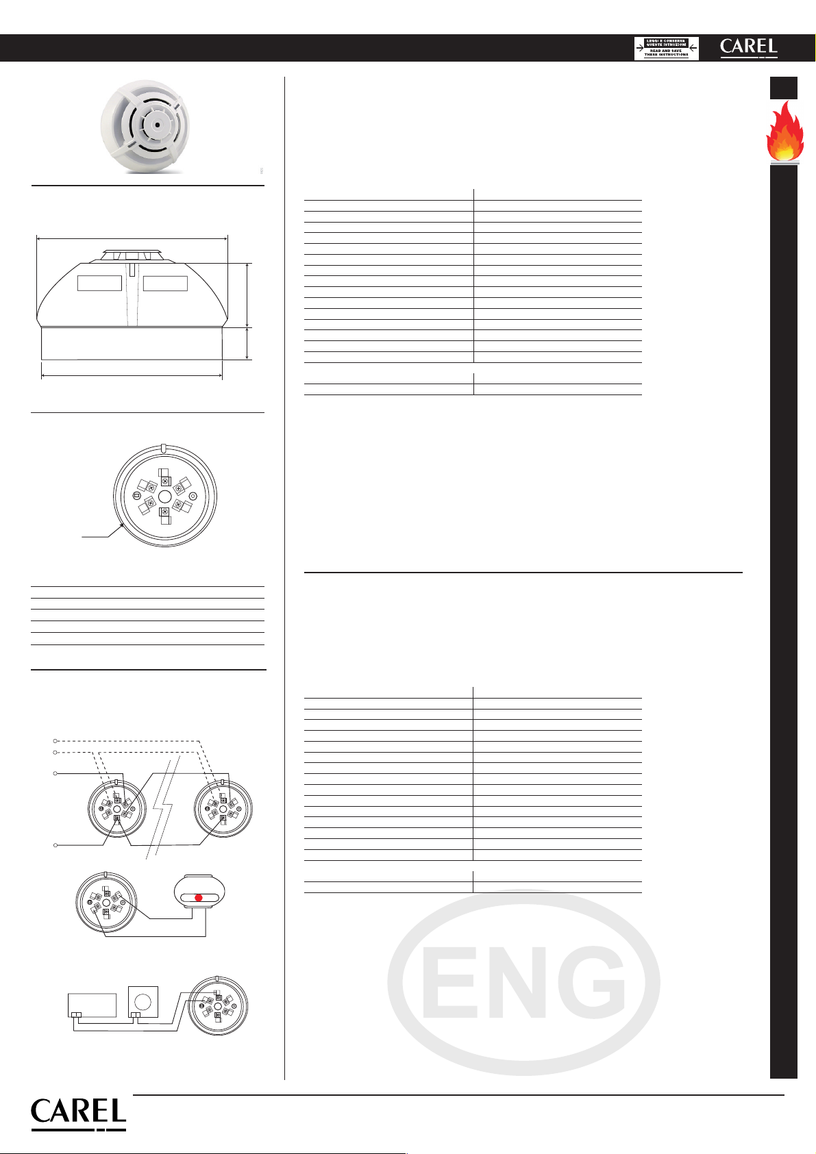
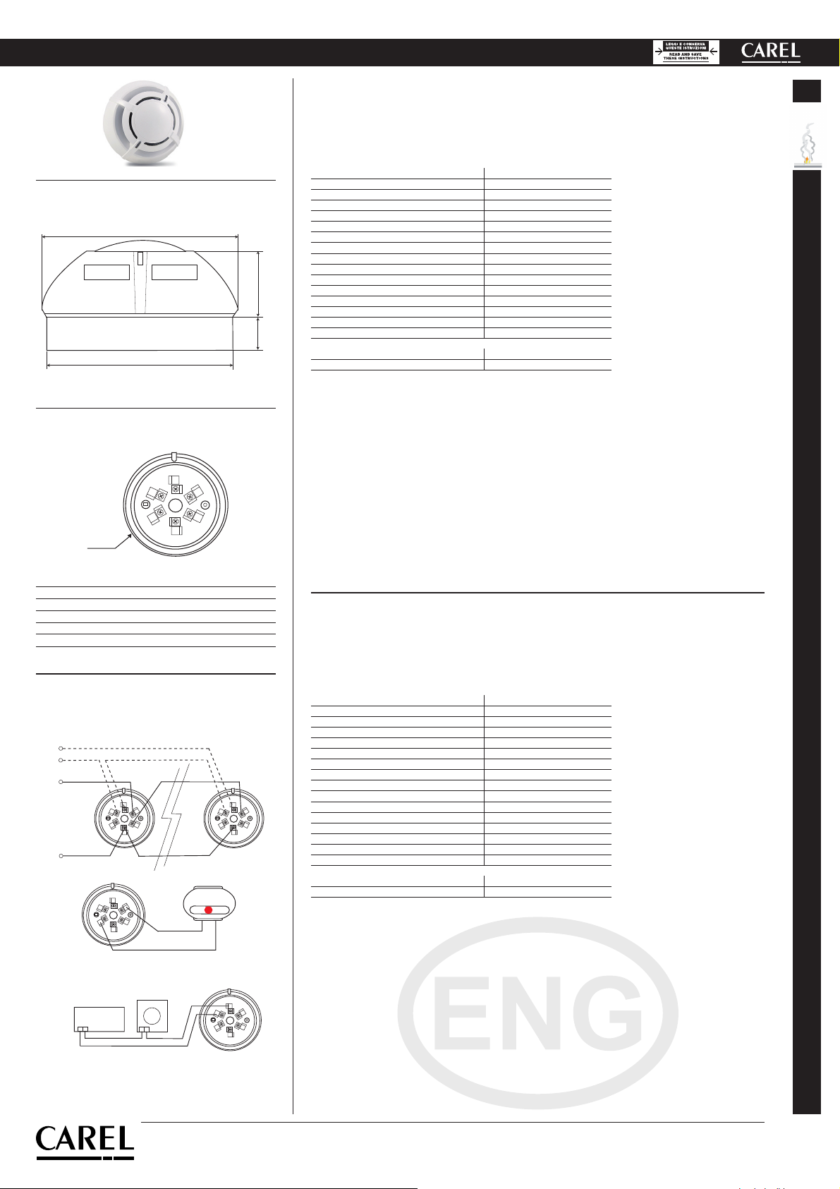
1/+ ポジティブライン入力 / Positive line input
2/R リレー / Relay
3/R リレー / Relay
4/SCR リピータの負出力 / Repeater neg. output
5/- ネガティブライン / Negative line
6/+ ポジティブライン出力 / Positive line output
100
20 39
106
1
2
3
4
5
6
リード
Fig. 1
寸法/ Dimensions
電気接続 / Electrical connection
Fig. 2
Fig. 3
cod. +050000520 - rel. 1.5 - 21.04.2015
CAREL INDUSTRIES HQs
Via dell’Industria, 11 - 35020 Brugine - Padova (Italy)
Tel. (+39) 049 9716611 – Fax (+39) 049 9716600
Description
The optical smoke detector senses the presence of combustion byproducts (visible smoke). The operating
principle is based on the light scattering technique (Tyndall effect). The detector is used as an active compo-
nent in alarm systems requiring a fire detection line. The device can be integrated into Carel controllers, and
is made in compliance with EN 54-7.
Technical specications
Plastic ABS
Colour White
Power supply 12...28 Vdc
Normal current 50μA a 24 Vdc
Alarm current 25mA a 24 Vdc
LED visibility 360° (double led)
Storage temperature -10…+70°C
Operating temperature -10…+70°C
Max. speed air 0,2 m/s
Relative humidity <93% not-condensing
Index of protection IP 20
Testing by magnet Yes
Relay max. 1A 30Vdc
Signal repeater 14mA a 24 Vdc
Sensor coverage: 40m2max
Shielded connection cable sez. min 0,5 mm2
Code Power supply
SFFS000000 12 to 24 Vdc
Tab. 1
Maintenance
For correct detector operation, periodical maintenance must be performed depending on the country disposal.
Periodical testing
Check correct detector operation using a smoke generator (making sure not to damage or dirty the sensor).
An alarm can also be simulated by activating the internal reed switch by magnet at the point marked “Reed”
on the wiring diagram. Note however that the reed test does not verify correct smoke detection.
Cleaning
Clean the detector periodically by blowing compressed air into the detection chamber. Remove the detector
by unscrewing the two screws and open the detection chamber. After cleaning reassemble the unit, paying
special attention to the position of the base (make sure the internal reed switch is aligned with number 4
stamped on the base). Close the detector using the two screws, without over-tightening.
配線図 /
Wiring diagrams
1
2
3
4
5
6
1
2
3
4
5
6
TAMPER
+LINEA
-LINEA
リピーター / Repeater
1
2
3
4
5
6+-
1
2
3
46
+-
POWER
SUPPLY +
-
5
リレーへの接続 / Connection to Relay