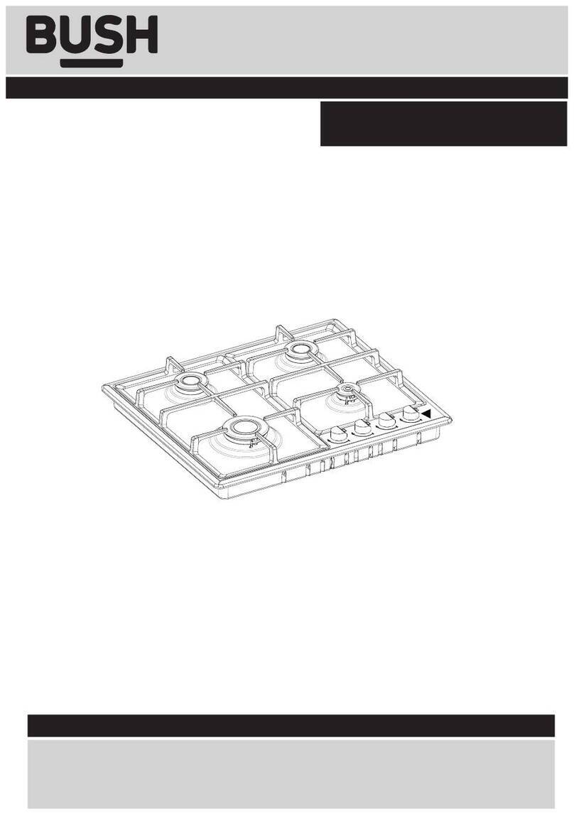
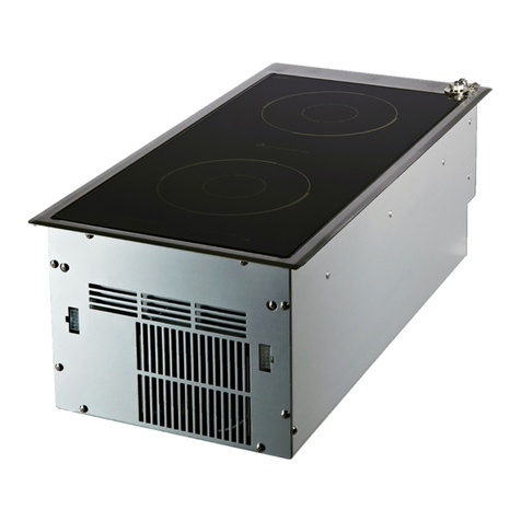
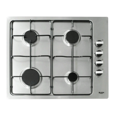
Bush LSG60HSS User manual

Instruction manual
#VJMUJO(BT)PC
LSG60HSS

You’ll soon be enjoying your new #VJMUJO(BT)PC
It all begins here, with your instructions. Don’t worry,
there’s nothing too technical coming up. Just simple,
step-by-step guidance to get you up and running
quickly. Sound good? Then let’s get started.
Help and Guidance
We’re here to help you get the most from your #VJMUJO(BT)PC. Should you require
any guidance, a simple solution can often be found online at:
www.CVTI- support.com
If you still require further assistance, call one of our experts on 01759 487838.
If you require any technical guidance or find that your product is not operating as intended, a simple solution can often be found in the Troubleshooting section of these instructions,

3
or online at www.CVTI- support.com If you still require further assistance, call one of our experts on 01759 487838
Contents
Care and Maintenance
6
7
8
Cleaning
3PVUJOFNBJOUFOBODF
Technical TQFDJGJDBUJPOT
Product support
Troubleshooting
30
31
32
Help and assistance
Declaration of conformance to product
standards
5
6
6
11
12
14
14
16
18
19
22
23
Safety information
Safety information
Getting to know your
#VJMUJO(BT)PC
Installing your #VMJUJO(BT)PC
Using your #VJMUJO(BT)PC
Controls
Using the (BT)PC#urners
1
2
3
4
0WFSWJFX
1MBDFNFOUPG#VSOFS)FBETBOE$BQT
"EWBODF1SFQBSBUJPO
1PTJUJPOJOHUIF)PC
*OTUBMMJOHUIF)PC
(BT$POWFSTJPO
&MFDUSJDBM$POOFDUJPO


1
Safety information

Safety information
Important - Please read these instructions fully before
installing or operating
Safety information
6
If you require any technical guidance or find that your product is not operating as intended, a simple solution can often be found in the Troubleshooting section of these instructions,
*/45"--"5*0/8"3/*/(4
IMPORTANT: This product MUST be installed
by a qualified Gas Safe registered installer in
accordance with local regulations. Particular
attention should be given to the ventilation
requirements.
IMPORTANT: Prior to Installation ensure that
the local supply conditions (electricity
voltage and frequency) are compatible with
the requirements of your cooker.
IMPORTANT: Carefully unpack and examine
the appliance for any damage. If you think
there is a defect, do not use the appliance
and contact Bush Product Support on 01759
487838. Packaging materials should be
collected together and disposed of
immediately as they may be harmful to
children.
IMPORTANT: Keep the electrical cable of
your gas hob away from the hot areas of
your cooker; do not let the cable touch the
appliance. Keep the cable away from sharp
edges and heated surfaces.
IMPORTANT: Ensure that the electric supply
cable is not trapped or damaged during
installation.
IMPORTANT: In the event that the cable
connecting your gas hob becomes
damaged, it must be replaced by a suitably
qualified person. This cable must not be
replaced by an unauthorised person.
IMPORTANT: Protect your gas hob against
atmospheric effects. Do not expose your gas
hob to effects such as sun, rain, snow etc.
IMPORTANT: The materials surrounding the
appliance (cabinets) must be able to
withstand a minimum temperature of 100°C.
%63*/(64"(&
IMPORTANT: This appliance can be used by
children aged from 8 years and above and
persons with reduced physical, sensory or
mental capabilities or lack of experience
and knowledge if they have been given
supervision or instruction concerning use of
the appliance in a safe way and understand
the hazards involved. Children shall not play
with the appliance. Cleaning and user
maintenance shall not be made by children
without supervision.
WARNING: The appliance and its accessible
parts become hot during use. Care should
be taken to avoid touching heating
elements. Children less than 8 years of age
shall be kept away unless continuously
supervised.
WARNING: Cooking on a hob with fat or oil
can
be dangerous and should not be left
unattended.
WARNING: NEVER try to extinguish a
cooking fire with water. Instead switch off
the appliance and cover flame e.g. with a lid
or a fire blanket.
CAUTION: Do not allow children in the
kitchen when cooking or while hob parts
may still be hot. Many parts of the hob will
become hot and present a considerable
hazard to children.
WARNING: Before obtaining access to
terminals, all supply circuits must be
disconnected.
Safety information
Important - Please read these instructions fully before
installing or operating
Safety information
7
or online at www.CVTI- support.com If you still require further assistance, call one of our experts on 01759 487838
IMPORTANT: Position pans over the centre
of the burners and turn handles to a safe
position where they can not be knocked or
grabbed.
IMPORTANT: Make sure the gas hob control
knobs are all in the off position when not in
use.
IMPORTANT: If you do not intend to use
your gas hob for a long period of time turn
off the gas and electric supply to the gas
hob.
CAUTION: Using gas cooking appliances
results in the production of heat, moisture
and the products of combustion. Ensure that
the room where your gas hob is installed is
well ventilated particularly while the gas hob
is in use. Keep natural ventilation holes open
or install a mechanical ventilation device
(extractor hood) Prolonged intensive use of
your gas hob may call for additional
ventilation (by opening a window) or by
increasing the level of mechanical ventilation
where present.
GENERAL SAFETY WARNINGS
IMPORTANT: This appliance has been
designed for non-professional, domestic
use only. Do not use this gas hob for
commercial use or any other application
e.g. room heating.
IMPORTANT: Do not hang towels,
dishcloths or clothes from the hob or its
controls.
CLEANING AND MAINTENANCE
IMPORTANT: Always turn the appliance
off before operations such as cleaning or
maintenance.
IMPORTANT: Do not remove the control
knobs to clean the control panel.
WARNING: Do not use harsh abrasive
cleaners or sharp metal scrapers to clean
the glass since they can scratch the
surface, which may result in shattering of
the glass.
TO MAINTAIN THE EFFICIENCY AND
SAFETY OF YOUR APPLIANCE, WE
RECOMMEND YOU ALWAYS USE OUR
AUTHORISED SERVICE AGENTS AND
ORIGINAL SPARE PARTS.
FOR ASSISTANCE CALL BUSH
PRODUCT SUPPORT 01759 487838.
WARNING: Danger of fire: do not store
flammable items on or near the cooking
surfaces or inside the oven.
IMPORTANT: Your appliance is produced in
accordance with all applicable local and
international standards and regulations.
IMPORTANT: Maintenance and repair work
must only be performed by authorised
service
technicians. Installation and repair work that
is carried out by unauthorised technicians is
dangerous and could invalidate your
guarantee.
CAUTION: Before starting to use your
appliance, ensure curtains, paper or
flammable items are
kept away from your appliance. Do not keep
flammable materials inside of or around
your gas hob.
WARNING: If the surface is cracked, switch
off the appliance to avoid the possibility of
electric shock.


Getting to know yoVS
#VJMUJO(BT)PC 2

Getting to know your #VJMUJO(BT)PC
10
If you require any technical guidance or find that your product is not operating as intended, a simple solution can often be found in the Troubleshooting section of these instructions,
Getting to know your#VJMUJO(BT)PC
You’ll be up and running in no time
Ready? Let’s begin...
Please read these instructions carefully. They contain
important information which will help you get the best
from your #VJMUJO(BT)PC and ensure safe and
correct installation and operation.
If you require any further assistance, our technical
experts are happy to help. For full details, refer to
the product support section at the end of these
instructions.

!
Getting to know your
You’ll be up and running in no time
RS
S A
Rapid Burner
11
or online at www.CVTI- support.com If you still require further assistance, call one of our experts on 01759 487838
Getting to know your Built-in Gas Hob

Getting to know your #VJMUJO(BT)PC
2
If you require any technical guidance or find that your product is not operating as intended, a simplesolution can often be foundin theTroubleshootingsection of these instructions,
1MBDFNFOUPG#VSOFS)FBETBOE$BQT
'PSBMMCVSOFST
Place a burner cap on each burner head (see
Figure ), matching the cap size to the head
size. The cap for each burner has an inner
locating ring which centers the cap correctly
on the burner head. Be sure that all the burner
caps and burner heads are correctly placed
BEFORE using your appliance.
Make sure each burner cap is properly
aligned and level (see Figure ).
Turn the burner on to determine if it will
light. If the burner does not light, contact
a qualified service center. Do not service the
sealed burner yourself.
4VSGBDF$PPLJOH6UFOTJMT
For lower gas consumption and better efficiency: Use only flat-bottomed pans of dimensions
suitable for the burners. Check for flatness by rotating a ruler across the
bottom of the pan. There should be no gaps between the pan and ruler. As soon as a liquid comes
to a boil take care to turn the flame down to a level that will just keep it simmering.
Specialty pans (lobster pots and pressure cookers) may be used but must conform to the recommended
cookware requirements.
Getting to know your#VJMUJO(BT)PC
You’ll be up and running in no time

Installing your
#VJMUJO(BT)PC 3

Installing your
Bringing it all together
If you require any technical guidance or find that your product is not operating as intended, a simple solution can often be found in theTroubleshooting section of these instructions,
RISK OF ELECTRIC SHOCK
DO NOT OPEN
CAUTION
CAUTION:
!" #$ %&' $ !($ # )* + " ,- $.$'!#)'
*("'+/ % "- 0"! #$1"2$- ' "2 $#
3"# 45 '+67 0" & *$ #8*$# 2)' $5 4.$
95#! *-) 0*)% $7-#$,$# -* $# 2)')0: !"
;&5.),)$% -* $#2)' $-9$ # *" 00 $.7
RISK OF ELECTRIC SHOCK
DO NOT OPEN
CAUTION:
!" #$ %&' $ !($ # )* + " ,- $.$'!#)'-*("'+/
%"- 0"! #$1"2$- ' "2 $#-3"# 45 '+67
0" & *$ #8*$# 2)' $5 4.$-95#! *-) 0*)%$7
#$,$# -* $# 2)')0: !"-;&5.),)$% -* $#2)'$
9$ # *" 00 $.7
!
(Fig. .1) and
(Fig. .2).
NOTE:
NOTE:
Fig. .1.
(Fig. .2).
(Fig. .2).
There must be a minimum air gap of 10 mm under
the hob. Failure to maintain a suitable
clearance may impair the performance of
the hob (Fig. .2).
Getting to know your #VJMUJO(BT)PC
14
410 mm
650 mm
470 mm
75 mm
550 mm
500 mm
470 mm
580 mm
550 mm
60 mm
Fig. .1

Installing your #VJMUJO(BT)PC
Bringing it all togetIFS
Installing your #VJMUJO(BT)PC
15
or online at www.CVTI- support.com If you still require further assistance, call one of our experts on 01759 487838.
NOTE: If the built-in hob is being installed directly
above
a built-in oven, an additional spacer (not supplied)
may be required to maintain a clearance of 10
mm between the underside of the built-in hob
and the top of the built-in oven Fig. .3.
Any hob hood should be installed in accordance
with the hood manufacturer’s instructions.
Any splashback must be fitted in accordance with
the manufacturers instructions. Allowance should
be made for the additional height of the flue trim,
which is fitted to the cooker hob.
Surfaces of furniture and walls at the sides and rear
of the hob should be heat, splash and steam
resistant. Certain types of vinyl or laminate kitchen
furniture are particularly prone to heat damage and
discolouration.
We cannot accept responsibility for damage
caused by normal use of the hob to any
material that de-laminates or discolours at
temperatures less than 65°C above room
temperature.
For safety reasons curtains must not be fitted
immediately behind the hotplate.
10 mm
Clearance
Door
Wall
65 mm
Space for
connections
Fig. .2
Fig. .3
2 mm
Oven
*
Hob Worktop
Spacer
Front fascia
IMPORTAN
T
* To achieve a 10 mm gap clearance, a spacer may be
required when installing directly above a built-in oven.

Installing your #VJMUJO(BT)PC
Bringing it all together
Installing your #VJMUJO(BT)PC
16
If you require any technical guidance or find that your product is not operating as intended, a simple solution can often be found in the Troubleshooting section of these instructions,
'JYJOHUIFTFBMUPUIFCBDLPGUIFIPC
The hob must be sealed to the work surface to
prevent liquid from entering into the cabinet. A tape
seal is supplied with the hob. Refer to Fig. 3.4.
1. Turn the hob over and place in on a secure, level surface.
Spread the longer seal “A” around the inner left, rear and right sides.
,
3. With a cutter or scissors cut the excess seal and retain for
next use.
Spread the seal “B” around the left, front and right outer edges of the
cooktop.
5.
'BTUFOJOHUIF*OTUBMMBUJPO#SBDLFUT
Each cooktop is provided with an installation kit
including brackets and screws for fastening the
top to fixture panels from 20 to 40 mm thick.
Refer to Fig. 3.4.
1. Turn the cooktop upside down and fasten the
brackets “F” and “R” to the appropriate socket
holes, without tightening the screws for the
moment.
Make sure that the brackets are fastened.
*OTUBMMJOHUIF)PC
2.
4.
Spread the seal “C” along the rear edge of the cooktop.
Making sure that the beginning and the end overlap at
the seal “B”.
2.
1. Turn the hob back the right way up and
position it in the worktop cut-out.
2. Insert the cooktop into the hole and position it correctly.
3. Adjust the position of the brackets “F” and “R”
and tighten the “Rear Screw” and “Front Screw”
to lock the cooktop firmly in position (Fig. 3.5).
4. With a sharp cutter or trimmer knife trim the
excess sealing material around the edge of the
cooktop. Take care not to damage the
workbench.
If the surface that the hob is to be fitted is tiled,
or is not reasonably smooth, additional sealing
with a waterproof silicone sealant may be
required.

Installing your #VJMUJO(BT)PC
Bringing it all together
Front sideRear side
RF
Front
Screw
Rear
Screw
Knobs
Fig. .5
Fig. .4
The picture is for reference only
Installing your #VJMUJO(BT)PC 17
or online at www.CVTI- support.com If you still require further assistance, call one of our experts on 01759 487838.
Rear side (R)
Front side
Gas Connection
Rear Screw (R)
Gas Connection
seal C
Rear Screw (R) seal C overlaps
seals B
Mains
Connection
seal C overlaps
seals B
seal B
seal A
Front Screw (F)
Front Screw (F)
ont

Installing your #VJMUJO(BT)PC
Bringing it all togetIFS
Gas Conversion (NG to U-LPG)
Converting to a dierent gas type
CONVERSION TO A DIFFERENT GAS TYPE MUST BE
CARRIED OUT BY A SUITABLY QUALIFIED GAS SAFE
REGISTERED INSTALLER
Changing the jets
1. Remove pan supports, burner heads and caps.
2. Use a size 7 socket wrench to unscrew and remove
the jets, replacing them with those supplied in the
conversion kit. Ensure you use the correct jet for
the corresponding burner.
3. Reassemble the burner heads, caps and
pan supports.
4. Fit the Gas type label supplied in the conversion
kit next to the gas connection point and remove
the existing label.
Setting the minimum level
1. Light one of the burners and turn the tap
to minimum flame.
2. Remove the corresponding control knob.
3. Use a thin blade screwdriver to turn the by-pass
screw located above left of the gas valve shaft.
Turn the by-pass screw fully clockwise.
The result should be a small, stable flame which is
uniform around the entire burner ring. If not, turn
the by-pass screw anti-clockwise until satisfied with
the flame.
4. Check that the burner does not go out when the
tap is turned quickly from the maximum to the
minimum position.
5. Repeat for each burner.
"DDFTTPSJFT
1. Bracket*4
2. Screw*4
3. Seal*1
4. LPG Nozzel*4
Installing your #VJMUJO(BT)PC
18
If you require any technical guidance or find that your product is not operating as intended, a simple solution can often be found in the Troubleshooting section of these instructions,

&MFDUSJDBM$POOFDUJPO
Before making the connection, make sure that:
1) The safety circuit-breaker and the electrical system are able to with stand the load of the
appliance.
2) The power supply system has a ground connection in good working order in accordance with
the regulations in force.
3) The electrical socket is easily accessible with the appliance installed. In all cases, the power
supply lead must be positioned so that it does not reach a temperature 50oC above the
room temperature at any point.
4) If installed above a built-in oven, the cooktop cable must not touch the oven below.
Installing your #VJMUJO(BT)PC
Bringing it all togetIFS
3FQMBDJOHUIFQPXFSTVQQMZMFBE
If the lead has to be replaced, only HO5RR-F or
HO5RN-F type cables suitable for the load and the
operating temperature must be used. In addition, the
yellow/green earth wire must be about 2 cm longer than
the live and neutral wires.
Installing your #VJMUJO(BT)PC
19
or online at www.CVTI- support.com If you still require further assistance, call one of our experts on 01759 487838.

Table of contents
Other Bush Hob manuals

Bush
Bush BPIH60B Assembly Instructions

Bush
Bush A60CT Product guide

Bush
Bush BSINDHB User manual

Bush
Bush BPGH60X Assembly Instructions

Bush
Bush BPCH60B BLACK Assembly Instructions

Bush
Bush B5BGHSS User manual

Bush
Bush LSBGHP User manual

Bush
Bush AG60GNSS Product guide

Bush
Bush DHG60GNSS User manual

Bush
Bush A60CK Product guide