Bushman DC285L-X Training manual

User Manual &
Operating Instructions
DC-L Series
CARAVAN – MARINE – RV - OFFGRID

Congratulations on your purchase of a Bushman DC-L fridge. Please read these instructions carefully
before installation and use.
Please be safe and use common sense and caution when installing, operating and cleaning this appliance. If
you are unsure about any of these instructions, contact your local dealer before proceeding.
IMPORTANT INFORMATION
Do not lay your fridge on its back, top or sides or at any angle exceeding 30º. If your fridge has been
incorrectly handled, ensure that the fridge is placed in a level upright position for 12 hours to allow the internal
fluids to redistribute evenly.
Never operate your fridge directly from a 240 V or AC power supply.
Do not use a modified sine wave inverter to operate your fridge.
PRIOR TO INSTALLATION
DELIVERY
At delivery, please check that the fridge is complete and is not damaged in any way. Remove all packaging
and securing tapes from the fridge. To avoid injury and causing damage to the appliance, be extremely
cautious when using sharp or pointed tools to complete this task.
Do not connect an appliance that has been damaged, contact your local stockist immediately.
INSTALLATION
Installation of the DC-L range of fridges must be completed by a suitably trained professional only.
POWER SUPPLY
Your fridge must be connected to a stable and regulated 12 V or 24 V DC power supply only. The compressor
will automatically detect which voltage is present adjust accordingly.
If you are using a generator or other power supply, the output must be a pure sine wave. Any fluctuations in
generator current may damage the compressor.
WIRING
For optimum results, you will need the correct sized wire depending on the distance from your power supply
to the fridge. Wiring must be directly from your fridge to your battery and should be continuous without joins.
Please also ensure the earth is wired directly to your battery, not to a chasse. If your wiring is insufficient,
your fridge may not perform correctly or may be even be damaged.
CROSS
SECTION
IN MM2
MAXIMUM LENGTH OF WIRE IN
METRES
12 V
24 V
2.5
2.5
5
4
4
8
6
6
12
10
10
20
We recommend installing a power switch for the fridge circuit as close to your battery bank as possible. Any
switches must have a breaking load not less than 20 A on 12 V or 10 A on 24 volts.
Ensure the wiring polarity is correct. Connect the red wire to the positive terminal (+) and the black wire to the
negative terminal (-).
Never connect bare electric wires. Use only connections of a size suitable for the cross section of the wire
being used.

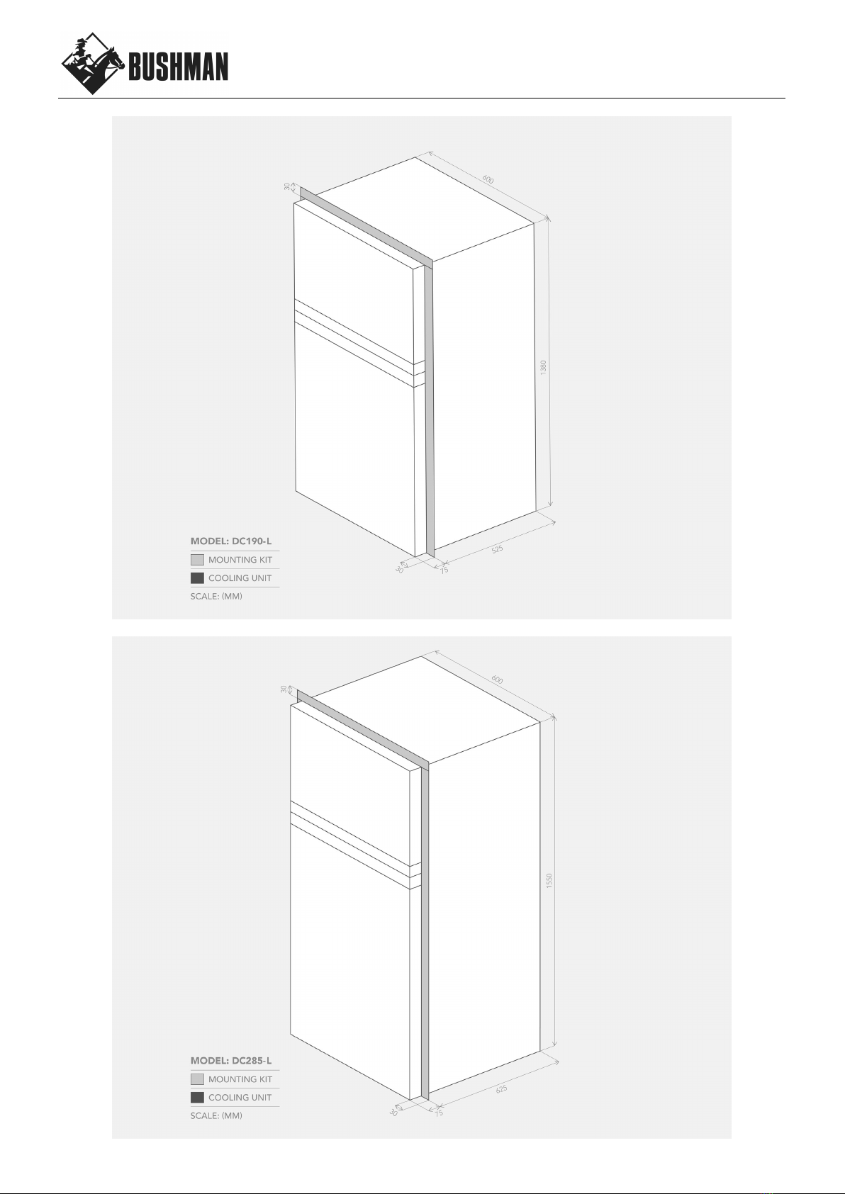
INSTALLATION IN A CAVITY WITH THE MOUNTING KIT
DC-L fridges are designed to be installed in a cavity. We recommend allowing a minimum 5mm gap in width
and height for ease of installation. A minimum gap of 50mm is recommended for the rear. Refer to the
following table for the recommended cut-out dimensions.
MODEL
CUT-OUT CAVITY DIMENSIONS (MM)
WIDTH
DEPTH
HEIGHT
DC190-L
605
575
1385
DC285-L
605
675
1555
VENTILATION
Two vents need to be provided from the rear of the fridge cavity to the outside environment, or to the general
area where the fridge is located. The vents should be located at the bottom and top of the fridge cavity and
have a free cross section of at least 300cm2 each. This allows for natural thermal air flows across the
condenser. As a general rule, the more ventilation you can provide, the better.
MOUNTING KIT
The mounting kit is first affixed to the side and top of the fridge cabinet using the screws provided.
Once the fridge has been connected to the power supply and moved into its final position, the mounting kit
can be affixed to the front of the cavity.
OPERATING THE FRIDGE
THERMOSTAT
• The cooling level can be set between 1 and 7.
• 7 is the coldest setting and 1 is the warmest.
EQUALISING THE FRIDGE
During the first 24 hours of operation, your compressor will operate for longer than usual. This process allows
the internal air temperature, food, drinks, condenser and insulation to equalise.
ENERGY SAVING TIPS
• Have a much ventilation as possible – the more the better.
• Keep the fridge out of direct sunlight whenever possible
• Only open the fridge or freezer door when necessary
• Allow hot food to cool down before placing inside the fridge
• Defrost the fridge as soon as a layer of ice forms
• Set the fridge to be only as cold as necessary
CLEANING
Wash the inside of your fridge with luke warm water and a mild soap. Never use abrasive or corrosive
cleaning agents, steel wool or scouring sponges. A soft sponge, towel, or soft brush is recommended.
Always keep the inside of the fridge clean and dry. Remove any condensate water or ice which gathers in or
near the tray under the freezer compartment.
Be careful when opening or closing the freezer door if ice has been allowed to accumulate in this area.
Keep the doors of the fridge ajar when the fridge is not in use, to allow fresh air to circulate inside the fridge
compartment.

DEFROSTING
Defrosting needs to be carried out when the ice layer reaches a thickness of 5mm.
Turn the fridge power off and move your food and beverages to another cool place. Do not use any objects to
remove the ice or frost, it must be allowed to melt naturally. Once the ice has melted, dry the inside of the
fridge and freezer compartment thoroughly.
REVERSING THE FRONT DOOR HINGES
The door hinges from the right side. To change the hinge side, simple unscrew the door hinges from the
fridge cabinet, move to the other side and re-affix using the same screws. Detailed instructions as follows:
• Carefully remove the top, middle and bottom hinges and both doors.
• Affix bottom hinge to the preferred side of fridge cabinet. Only tighten screws finger tight.
• Move the bottom hinge pin to the other side of the hinge.
• Locate main door onto the bottom hinge.
• Affix middle hinge to fridge cabinet. Only tighten screws finger tight.
• Locate freezer door onto the middle hinge.
• Affix top hinge to fridge cabinet. Only tighten screws finger tight.
• Align the freezer door until it is square with the fridge cabinet.
• Tighten top hinge screws fully.
• Align the main door until it is square with the fridge cabinet.
• Tighten bottom hinge screws fully.
• Tighten the middle hinge screws fully.
• With the doors closed, carefully apply moderate heat with a heat gun or hair dryer to the rubber seals
one section at a time. Once warm and softened, the rubber will pull in towards the fridge cabinet and
create a flush seal.
• If you are unsure at any stage, please call Bushman head office on (03) 9437 0737 for assistance.
TECHNICAL SPECIFICATIONS
DC190-L
DC285-L
COMPRESSOR
Secop BD50
Secop BD50
VOLTAGE
12 V / 24 V
DC
12 V / 24 V DC
REFRIGERANT
170g R134a
190g R134a
EXTERNAL
DIMENSIONS
(mm)
W 600
D 600
H 1380
W 600
D 700
H 1550
NETT WEIGHT
50 kg
62 kg

TROUBLE SHOOTING
VOLTAGE
The most common cause of an incorrectly functioning fridge is a lack of voltage.
Your fridge has built in battery protection and needs the following minimum voltage for the compressor to start
(Cut-in) or stop (Cut-out).
Battery Protection Settings
VOLTAGE
CUT OUT
CUT IN
12 V
9.6 V
10.9 V
24 V
21.3 V
22.7 V
During fridge operation, a load is placed on your power supply which can cause your voltage level to drop by
as much as 2 V. This occurs especially if the wiring in insufficient or if there is a loose connection somewhere.
If this occurs, your fridge may exhibit a continuous start / stop / start pattern. If so, have your wiring checked
by an electrician when under a 10 A load.
GENERAL TROUBLESHOOTING
Check:
• Correct power supply
• The built-in fuse
• The voltage to the compressor is still 12V when a 10 A load is placed on the wire
• The fan is operating
• The polarity of the connections are correct
• There is adequate ventilation to the rear of the fridge
• The fuse is not blown
• You have given the fridge enought time to cool down


VENTILATION
OPTIONS DC-L
Exterior Ventilation
Interior Ventilation Option 1
Interior Ventilation Option 3
min 300cm2
min 50mm
min 50mm
min 50mm
Interior Ventilation Option 4
Interior Ventilation Option 2
min 300cm2
min 200mm
min 50mm
min 50mm
min 200mm

WARRANTY
DP Refrigeration Pty Ltd trading as Bushman Fridges ABN 94 615 295 255 (Bushman) warrants, to the
original owner, that this product is free from defects in workmanship and material for a period of three (3)
years from the purchase date. This warranty shall be limited to repairing or replacing, at Bushman’s option
and without charge to the purchaser, defective components. All warranty work shall be performed at a
Bushman approved facility. Shipping charges related to returning the product to the Bushman facility are not
covered under this warranty. However, this warranty covers shipping charges related to returning the
repaired product to the customer. This warranty does not apply to damage or wear to the product caused by
accident, abuse, misuse, neglect, unauthorized alteration or repair, or if the product was not used in
accordance with Bushman printed installation and operating instructions. To obtain service under this
warranty, the defective product must be returned to Bushman together with a copy of the original purchase
receipt. Any product repaired or replaced under this warranty will be warranted for the balance of the warranty
period with respect to the original purchased product. Bushman is not liable for any incidental or
consequential loss or damages whatsoever as a result of use or misuse of this product. Any statutory
warranty also applies.
For after sales service and enquiries, please contact:
BUSHMAN FRIDGES
3 Contour Close Research VIC 3095
(03) 9437 0737
info@bushman.com.au
This manual suits for next models
4
Table of contents
Other Bushman Refrigerator manuals

Bushman
Bushman XD-200 User manual

Bushman
Bushman DC-X Series Training manual

Bushman
Bushman DC190-L Training manual

Bushman
Bushman XCD-100 User manual

Bushman
Bushman ROADIE System manual

Bushman
Bushman DC-X Series System manual

Bushman
Bushman SC 35 User manual

Bushman
Bushman DC190-L Training manual

Bushman
Bushman SC 35-52 System manual

Bushman
Bushman Roadie 15L System manual