-8-
CHECKOUT AND ADJUSTMENT
resonance and lowest VSWR occur at slightly higher frequencies on all
bands compared to ground-level installations. Therefore on 15 and 10
meters, where length adjustment is the means of getting antenna
resonance, it is recommended that the length of the stranded-wire
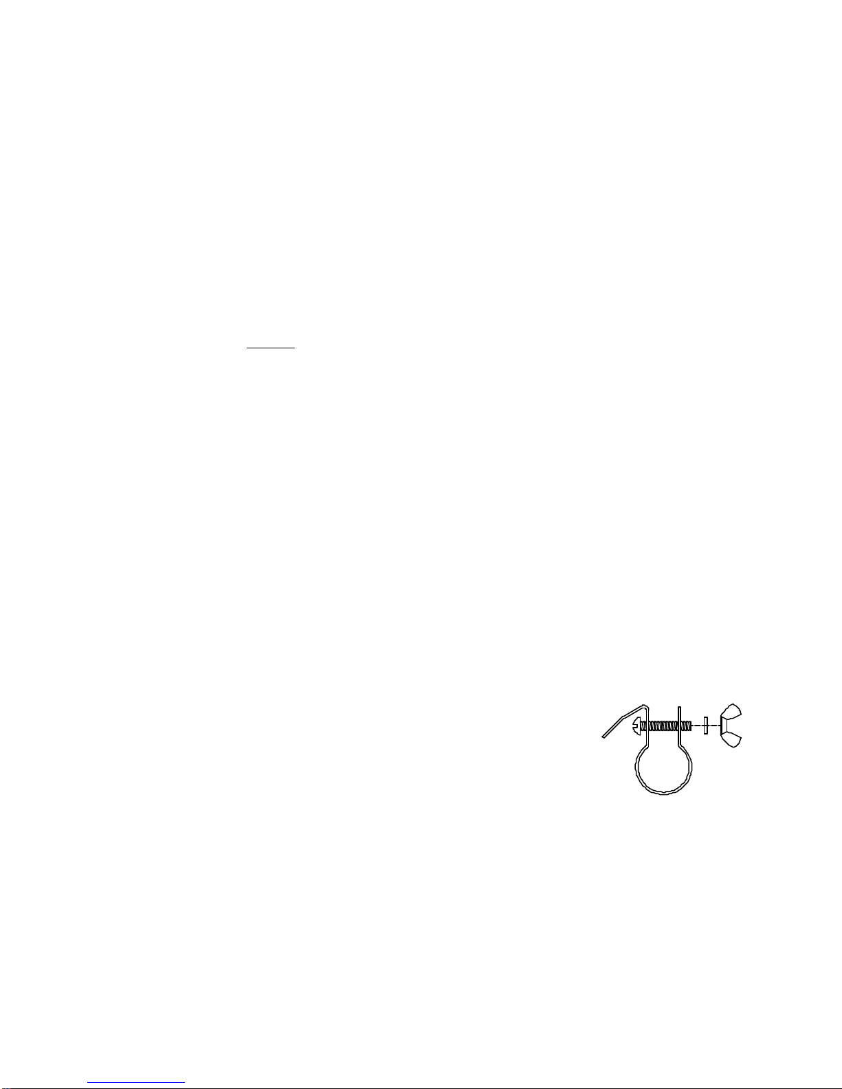
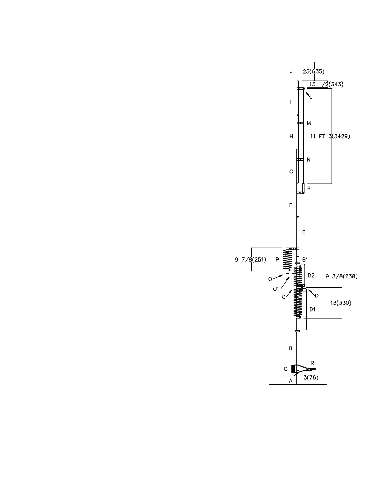
between wire clamp 0.500" 15 M w/wire (L) and wire clamp 0.875"
15 M w/insulator (K) be increased approximately 3 in (7.6 cm.) and
that tube (J) be extended approximately 6 in (15.2 cm.) beyond the
original dimensions given if any above-ground installation is
contemplated. These are merely recommended preliminary settings,
for it is impossible to indicate precise settings that will produce
resonance or lowest VSWR at a given frequency in all installations.
In the preceding steps it has been assumed that the antenna has been installed in a
more or less clear spot away from other vertical conductors such as TV antenna
feedlines, towers and masts, and that a minimal ground system (or a system of
resonant radials in the case of above-ground installations) has been installed.
If those fairly basic conditions have not been met it is likely that resonance and low
VSWR will be impossible on some or even all bands. One should bear in mind that
VSWR, even with a resonant antenna, will depend in large measure on local ground
conductivity, height above ground in the case of an elevated antenna, the extent of
the radial, counterpoise or other ground system used, and on other factors over which
the operator may have little or no control. Fortunately, the evils of VSWR greater than
unity have been grossly exaggerated in recent decades, and the only practical
difference between a VSWR of unity and one of, say, 3:1 in the average case lies in
the reluctance of modern equipment to deliver full power into lines operating at the
higher VSWR without the help of a transmatch or other outboard matching device.
Transmitters having so-called broadband solid-state output circuits (no tuning or
loading controls) may be especially troublesome in this regard, whereas the older
vacuum tube pi-network transmitters can usually be adjusted for maximum output over
a tuning range where the VSWR does not exceed 2:l.
THEORY OF OPERATION
The first L/C circuit generates enough reactance to bring the whole HF6V to resonance
on 80 meters allowing it to act as a 1/4 8radiator. It also generates enough capacitive
reactance to produce another discrete resonance at about 11 MHz. The second, 40
meter L/C circuit generates enough reactance to resonate the whole HF6V allowing it
to act as a 1/4 8radiator. In order to minimize conductor and I²R losses an 80 and 40
meters where the antenna is physically shorter than a 1/4 8and thus operates with
lower values of radiation resistance, large-diameter self-supporting inductors and low-
loss ceramic capacitors are employed. Where the height of the HF6V is slightly greater
than a 1/4 8on 30 meters, an L/C series tuned circuit taps onto the 40 meter coil for
the extra inductance to pull the earlier 11 MHz secondary resonance down to 10 MHz.
At the same time, a portion of the 40 meter coil is shorted out which allows the circuit
to resonate on 30 meters The addition of this circuit also produces additional
resonances at 14 MHz and 28 MHz. On 20 meters the entire radiator operates as a 3/8
8vertical with much higher radiation resistance and VSWR bandwidth than
conventional or trapped antennas having a physical height of 1/4 8or less. Because
the 20 meter radiation resistance will be several