manuals.online logo
Brands
  1. Home
  2. •
  3. Brands
  4. •
  5. Maxview
  6. •
  7. TV Antenna
  8. •
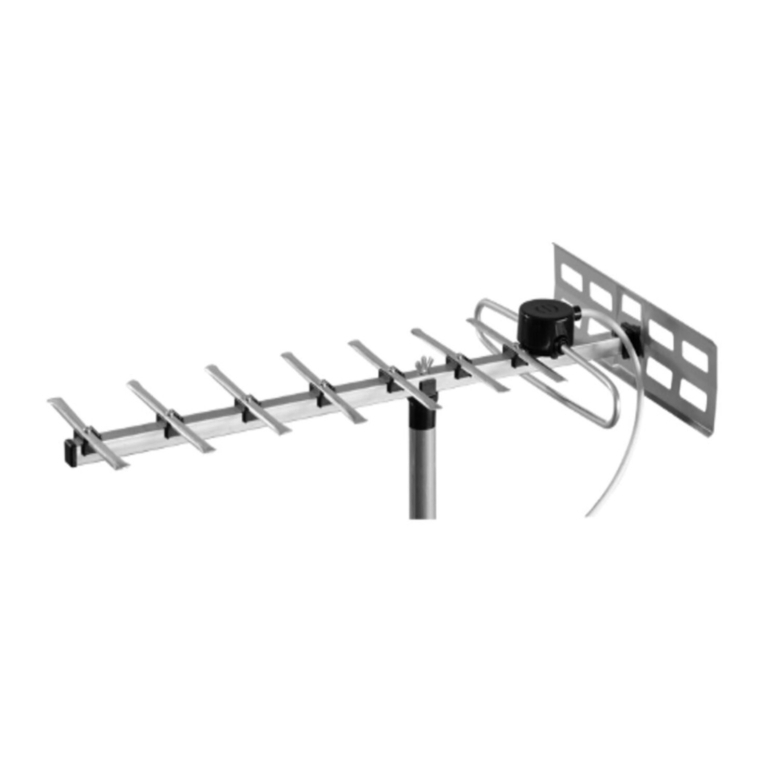
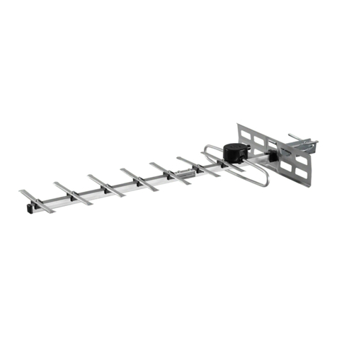
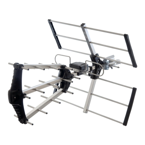
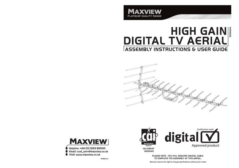
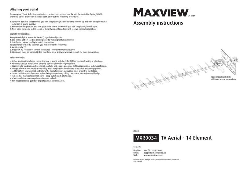
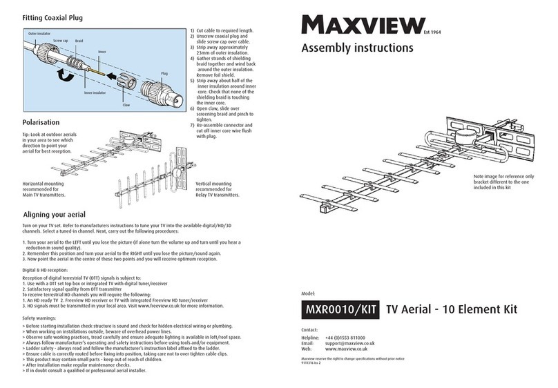
  9. Maxview 18 Element Owner's manual

Maxview 18 Element Owner's manual

This manual suits for next models

1

Other Maxview TV Antenna manuals

Maxview Omnimax Pro B2344/G User manual

Maxview

Maxview Omnimax Pro B2344/G User manual

Maxview Omnimax Pro B2344 User manual

Maxview

Maxview Omnimax Pro B2344 User manual

Maxview MXR0012 User manual

Maxview

Maxview MXR0012 User manual

Maxview MXL052 User manual

Maxview

Maxview MXL052 User manual

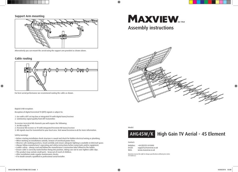
Maxview AHG45W/K User manual

Maxview

Maxview AHG45W/K User manual

Maxview MXR0010 User manual

Maxview

Maxview MXR0010 User manual

Maxview MXR0025 Configuration guide

Maxview

Maxview MXR0025 Configuration guide

Maxview MXR0010 User manual

Maxview

Maxview MXR0010 User manual

Maxview MXR0034 User manual

Maxview

Maxview MXR0034 User manual

Maxview MXR0024 User manual

Maxview

Maxview MXR0024 User manual

Maxview MXR0010/KIT User manual

Maxview

Maxview MXR0010/KIT User manual

Popular TV Antenna manuals by other brands

Winegard HD8200U instructions

Winegard

Winegard HD8200U instructions

BAS REMO BAS X3174 MIDI quick start guide

BAS

BAS REMO BAS X3174 MIDI quick start guide

Winegard GS-2200 user manual

Winegard

Winegard GS-2200 user manual

KVH Industries TracVision HD11 installation guide

KVH Industries

KVH Industries TracVision HD11 installation guide

Radio Shack VU-110XR owner's manual

Radio Shack

Radio Shack VU-110XR owner's manual

Labgear LAB450K user guide

Labgear

Labgear LAB450K user guide

Winegard HD-7015 instructions

Winegard

Winegard HD-7015 instructions

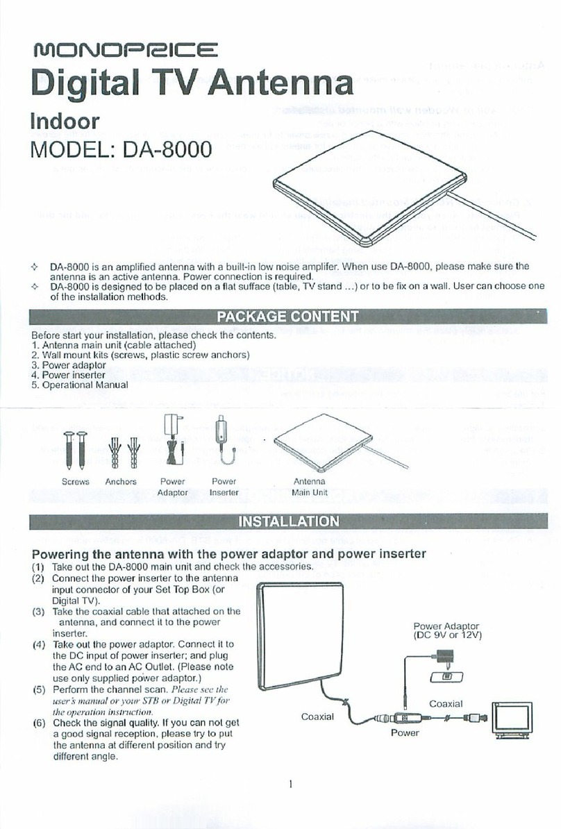
Monoprice DA-8000 instruction manual

Monoprice

Monoprice DA-8000 instruction manual

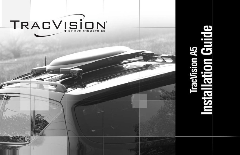
TracVision A5 installation guide

TracVision

TracVision A5 installation guide

Emos DTV-4 manual

Emos

Emos DTV-4 manual

IKUSI mini FLASHD quick start guide

IKUSI

IKUSI mini FLASHD quick start guide

nedis ANIR2512GY700 quick start guide

nedis

nedis ANIR2512GY700 quick start guide

Irradio Shield user manual

Irradio

Irradio Shield user manual

Labgear LLP12K user guide

Labgear

Labgear LLP12K user guide

Alcad 900 Series manual

Alcad

Alcad 900 Series manual

SLX 27776R user guide

SLX

SLX 27776R user guide

NoCable NC-001-IND manual

NoCable

NoCable NC-001-IND manual

KING Flex VQ2100 owner's manual

KING

KING Flex VQ2100 owner's manual

manuals.online logo
manuals.online logoBrands
  • About & Mission
  • Contact us
  • Privacy Policy
  • Terms and Conditions

Copyright 2025 Manuals.Online. All Rights Reserved.

Nut x 4
M5 x 25mm Screw x 4
Screw x 18
Mast Clamp x 1
Front Boom x 1
Rear Boom x 1
Vertical mounting
recommended or
Relay TV transmitters
Horizontal mounting
recommended or
Main TV transmitters
Tip: Look at outdoor aerials in your
area to see which direction to
point your aerial or best reception.
KIT CONTENTS - CHECK LIST
A
A:
B:
C:
D:
E:
F:
G:
H:
I:
J:
K:
L:
M:
N:
O:
P:
Q:
R:
S:
Support Arm x 1
Re lector Plate x 1
Dipole x 1
Saddle Clip x 16
Re lector Bung x 1
End Bung x 2
Joining Plate x 2
Support Arm Bracket x 4
6 ” Element x 1
6’’ Element x 3
5 ’’ Element x 5
5 ’’ Element x 7
Washer x 4
PLEASE NOTE - YOU WILL REQUIRE COAXIAL CABLE
TO COMPLETE THE ASSEMBLY OF THIS AERIAL.
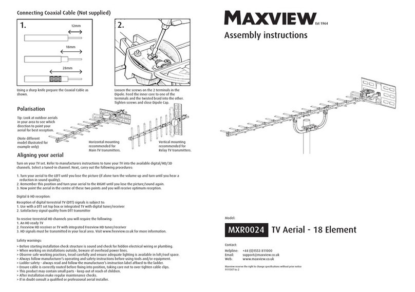
POLARISATION
■Ladder sa ety - always read and ollow the manu acturer’s instruction label a ixed to the ladder.
■When working on installations outside, beware o overhead power lines.
■Observe sa e working practices, tread care ully and ensure adequate lighting is available in lo t
or roo space.
■To avoid injury always route cables or wiring care ully.
■Always ollow manu acturer’s operating and sa ety instructions be ore using tools and/or equipment.
■Be ore starting installation check structure is sound and check or hidden electrical wiring or plumbing.
I in doubt consult a quali ied electrician or pro essional aerial installer
SAFETY FIRST - PLEASE READ
Turn on your TV set. Re er to manu acturer’s instructions
to tune your TV into the available digital or analogue
channels. Select a tuned-in analogue channel.
Next, carry out the ollowing procedures:
1. Turn your aerial to the LEFT until you lose the picture
(i alone turn the volume up and turn until you hear a
reduction in sound quality).
2. Remember this position and turn your aerial to the
RIGHT until you lose the picture/sound again.
3. Now point the aerial in the centre o these two points
and you will receive optimum reception.
ALIGNING YOUR AERIAL
9111307 Iss 1
1/2
TYPICAL AERIAL MOUNTING APPLICATION EXAMPLES
WALL AND LOFT FIXING KITS ARE AVAILABLE FROM WILKINSON (INCLUDES 10M COAXIAL CABLE)
You should mount your aerial as high as possible on either a chimney, on an external wall,
or in the lo t. Remember, that in general, TV pictures improve with height and the less
obstructions between the aerial and the transmitter the better.
Now point your aerial in the direction o the transmitter by looking at neighbours aerials and
copy the direction they are pointing. I you decide to it the aerial in your lo t, special care
should be taken when walking in the roo space.
Wall mounted Lo t mounted Chimney mounted
18 ELEMENT
DIGITAL TV AERIAL
ASSEMBLY INSTRUCTIONS & USER GUIDE
PLATINUM* QUALITY RANGE
MXR0024
■Helpline: +44 (0) 1553 811000
■Email: [email protected]
■Visit: www.maxview.co.uk
To tune in Digital Terrestrial Television channels re er to
manu acturer’s instructions o your DTT equipment.
B
C
DE
F
G
HMN
OP
IJ K L QR
S
1/4
1/4
Fit the support arm to boom o the aerial using the two joining plates. Secure with
nuts and bolts.
Join the 2 pieces o boom together
using the joining plate, M5 x 20mm
screws M5 nuts and 5mm shake
proo washers.
Screw the 6”, 6 1/4”, 5 1/2” and 5 1/4”
elements to the boom as shown
below. Take care not to over-tighten
screws.
Example o completed Boom and Element assembly.
Screw on irmly the Dipole to the Boom. Screw the Re lector Bung to the Boom.
Slide on and irmly push down the
Re lector onto the groove o the
Re lector Bung.
AERIAL ASSEMBLY INSTRUCTIONS
Attach aerial to a suitable mast*
using the supplied Mast Clamp.
(Note: Mast not supplied).
Element locations
61/4 ”
7
CONNECTING COAXIAL CABLE (NOT SUPPLIED)
*Wall/Lo t Fixing Kit and **Coaxial Cable Kit available rom Maxview
O
G
R
S
M
N
P
L
D
P
C
P
E
B
Q
6
12
3 4
8
F
5
Insert the square end bungs into the aerial boom.
O
HMN
6” 51/2 ”51/4 ”
Using a sharp kni e prepare the
Coaxial Cable** as shown.
Loosen the screws on the two terminals.
Thread Coaxial Cable through Dipole.
Ensure outer braid does not touch
inner core. Tighten screws and Dipole
lid.
12
1
2
3
12mm
18mm
28mm