Buyers Products Company TGS01B User manual

Quality since 1946
5
9049 Tyler Blvd. • Mentor, Ohio 44060
Phone (440) 974-8888 • Fax (440) 974-0165
Toll-Free Fax 800-841-8003 • buyersproducts.com
Installation Instructions
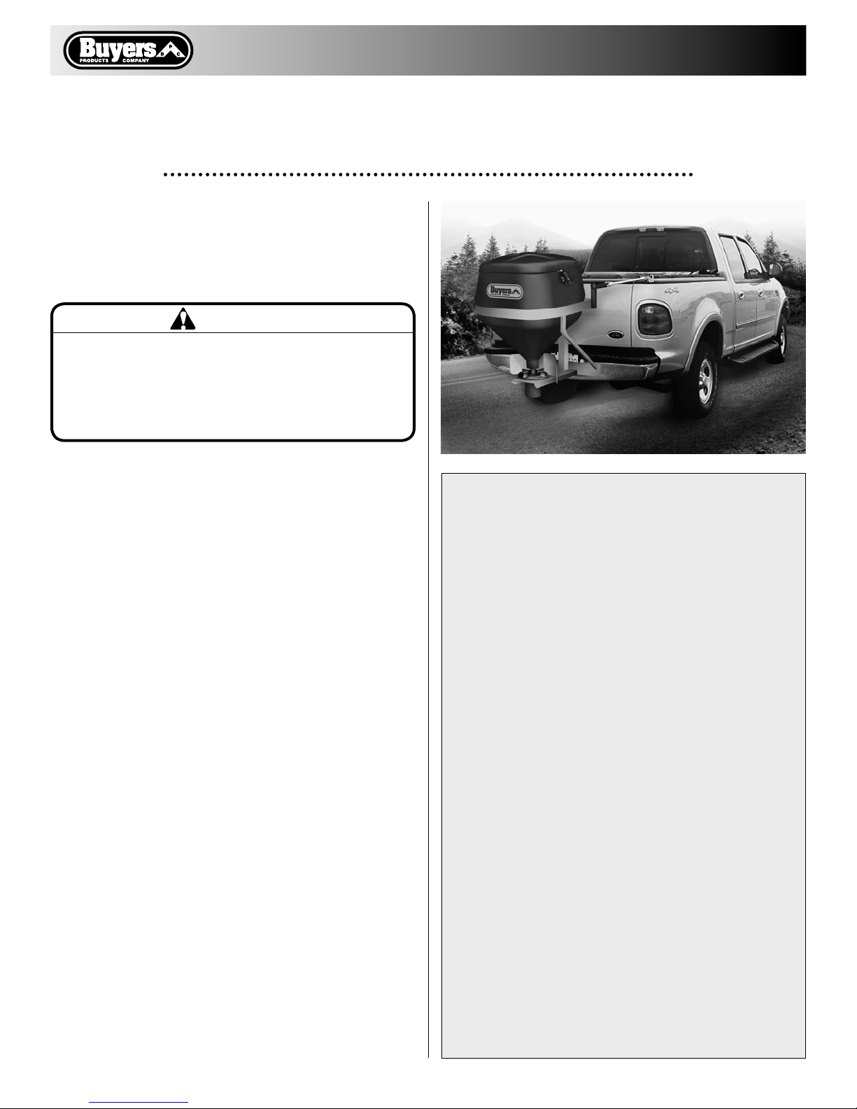
TGS01B Salt Spreader
—continued inside
WARNING
Observe the following Safety Precautions before, dur-
ing and after operating this spreader. By following
these precautions and common sense, possible injury to
persons and potential damage to this machine may be
avoided.
SPREADER WARRANTY INFORMATION
This warranty replaces all previous warranties and
no employee of this company is authorized to extend
additional warranties, or agreements, or implications
not explicitly covered herein.
Buyers Products Company warrants all parts of the
product to be free from defects in material and work-
manship for a period of one (1) year. Parts must be
properly installed and used under normal conditions.
Normal wear is excluded.
Any part, which has been altered, including modifica-
tions, misuse, accident, or lack of maintenance will
not be considered under this warranty.
The sole responsibility of Buyers Products Company
under this warranty is limited to repairing or replac-
ing any part(s), which are returned, prepaid, 30
days after such defect is discovered, and returned
part(s) are found to be defective by Buyers Products
Company.
Authorization from Buyers Products Company must
be obtained before returning any part. The following
information must accompany defective parts returned
to Buyers Products Company: RMA #, spreader model,
serial number, date installed, and distributor from
whom purchased.
Buyers Products Company shall not be liable for
damage arising out of failure of any unit to operate
properly, or failure, or delay in work, or for any con-
sequential damages. No charges for transportation
or labor performed on any part will be allowed under
this warranty.
Safety Precautions
1. Read this entire Owners Manual before operat-
ing this spreader.
2. Read all safety decals on the spreader before
operating.
3. Verify that all personnel are clear of the spread-
er spray area before starting or operating this
spreader.
4. Do not adjust, clean, lubricate or unclog material
jambs without first turning off the spreader.
5. Make sure the spreader is securely fastened to
the vehicle in accordance with this manual.
6. Do not operate a spreader that is in need of
maintenance or repairs.
7. Always disconnect the battery before removing
or replacing electrical components.
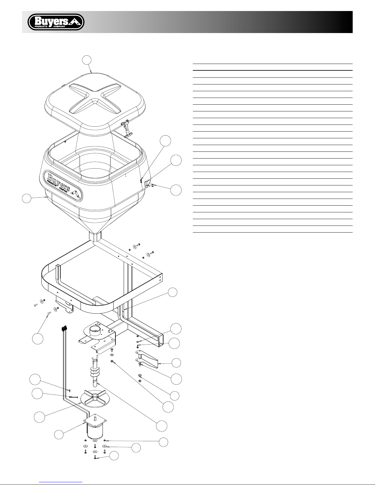
Spreader Assembly
Check contents of box against parts list to make
sure all components are included. When ordering
replacement or spare parts refer to parts list (fig. 3)
for part numbers.
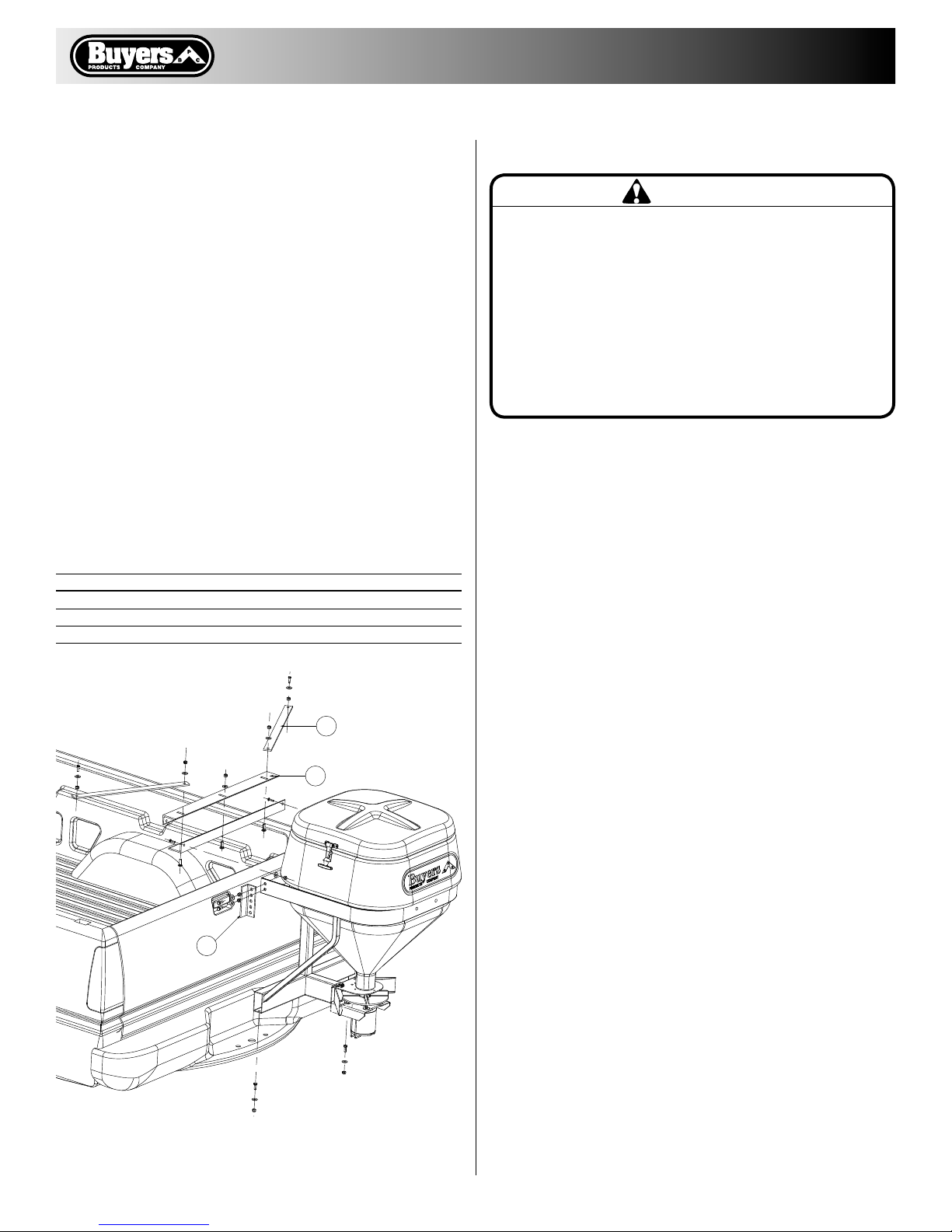
Installation (fig. 1)
1. Locate and mark center of tailgate.
2. Assembly Angles (24) and Braces (23) as shown
in Fig.1 Use 3/8" carriage bolts, flat washers and
nuts. Do not tighten fasteners at this moment.
3. Center assembly on top of tailgate. Lower angle
must be flush with top and inside surfaces of
tailgate.

Quality since 1946
2
4. Position braces (23) on top of side rails. Using
holes in braces as guides mark and drill holes for
3/8" screws.
5. Attach braces to side rails using 3/8" screws, flat
washers and nuts.
6. Center spreader assembly on top of rear bumper
and align with Angle (24).
7. Attach Mounting Angles (22) to spreader frame.
8. Make sure spreader frame is vertical. Using
holes in Angle (24), mark and drill holes for 3/8"
screws in Mounting Angle (22).
9. Using holes in spreader frame as guides, mark
and drill holes for 3/8" screws in rear bumper.
10. Assembly spreader to Angles (24) and rear
bumper. Adjust position of Angles (24) to bring
spreader into vertical position. Tighten all screws
at this moment.
11. Close tube with plastic caps provided.
WARNING
Do not drill holes into fuel tanks, fuel lines, through
electrical wiring, etc that may be damaged by drilling.
To insure good performance of your spreader, check
the condition of truck’s electrical system. Using digital
voltmeter, check alternator and battery voltage. With
engine running and head lights and heater fan ON good
voltage reading should fall between 13.0 and 15.3 volts.
If voltage reading falls out of this range, check and
adjust your electric system.
Torque Chart
1/4-20 6.0
5/16-18 11.0
3/8-16 20.0
Bolt/Nut Size torque (ft.-lbs.)
Electrical Installation (fig. 2)
1. Lay out path for the Red Wire (0203800) in the
truck’s engine compartment. This wire will be
connected to positive terminal on truck’s battery.
Drill hole in the firewall or use an existing one to
pass wire into cab. Do not route close to exhaust
system!
2. Lay out a wiring path for the Wire Assembly
222" long (0203600) toward rear bumper. Drill all
necessary holes or use existing ones to pass the
flat blade connector into the trucks cab. Attach
harness to truck’s frame. Do not route close to
exhaust system!
3. Install Socket Assembly (0203200) near rear
bumper. Remove paint/ primer and attach black
wire of this assembly to truck frame. Doing this
will insure good connection.
4. Connect Wire Assembly (0203600) to Socket
Assembly (0203200).
5. Mount the Controller (3006587) in a convenient
location in the truck cab. Connect Black ground
wire to truck’s frame or battery negative post (addi-
tional wire is required). Connection to battery neg-
ative post is recommended for newer trucks (2000
and up). It is recommended not to mount Controller
directly in front of the heat vents.
6. Make sure that the Controller is OFF. Connect
blue wire’s small female terminal to Controller’s
connector on controller’s rear wall. Connect the
blue wire to an accessory wire/terminal that is
controlled by the vehicle’s ignition switch. Connect
battery wire and 222" wire assembly to Controller.
7. Connect the Red Wire (0203800) ring terminals
to the battery positive post.
23
24
22
Fig. 1

Quality since 1946
3
8. Attach Adapter (3009863) to Socket Assembly
(0203200).
9. Connect Red motor wire to Red adapter wire and
Black motor wire to Black adapter.
10. Make sure Controller is OFF, start the truck.
11. Turn Controller ON. Adjust speed to desired
setting. Do not change speed abruptly! It may
stall motor.
12. Observe spinner direction of rotation. The cor-
rect direction is counter clock wise when looking
inside hopper from the top. If direction is clock
wise reverse wires between Motor and Adapter.
IMPORTANT
Make sure all wires securely attached to vehicle or
spreader’s frame. Use wire ties and/or wire clamps
to attach wires. All excess wires must be rolled into
bungles and attached to vehicle or spreader.
Spreader Maintenance
1. This spreader is designed to use loose free float-
ing materials such as #1 dry Rock Salt. Using differ-
ent grades and/or wet material will affect spreader
performance. Wet material can “bridge" and stop
floating onto spinner disk.
2. Make sure lid is installed and latches are
secured when spreader is in use.
3. Do not leave material in hopper between uses.
4. Do not drive with material in hopper.
5. Always clean/wash hopper at the end of the day.
6. Spray lubricant around motor shaft to prevent
water from penetrating into the motor.
7. Apply dielectric grease to all electrical connec-
tors between uses and for long term storage.
CAUTION
Do not attempt to install or remove spreader with
material in it.
Motor
3009476
Wire Assembly, Red 222"
0203600
Blue Wire
0203700
To Terminal Controlled
By Ignition Switch
Wire Assembly
To Battery
0203800
Black Wire
To Frame Or Battery
Negative Terminal
Adapter
3009863
Socket Assembly
0203200
To Truck Frame
Fig. 2

Quality since 1946
4
9049 Tyler Blvd. • Mentor, Ohio 44060
Phone (440) 974-8888 • Fax (440) 974-0165
Toll-Free Fax 800-841-8003 • buyersproducts.com
3011391 Rev. A
Bill of Materials
1 3005920 1 Frame, Weldment, TGS01B
2 3006095 1 Hopper w/ Sleeve, Assembly TGS01B
3 3003079 1 Lid, Assembly TGS01A
4 3009476 1 Motor 12 VDC, TGS
5 –4 Screw, Cap Hex HD 1/4-20 x 1 SST
6 –8 Washer, Fender 5/16" ID x 1-1/4" OD
7 –10 Nut, Nylon Insert 1/4-20 SST
8 3005913 2 Shield, TGS01B
9 –4 Washer, Flat 3/8 USS SST
10 –4 Screw, HHC 3/8-16 x 3/4 SST
11 –4 Nut, Nylock 3/8-16 x 7/16 SST
12 –2 Screw, Cap 1/4-20 x 3/4 SST
13 –2 Washer, Flat 1/4 SAE SST
14 3000626P 2 Keeper, Latch WJ201, Black
15 –4 Bolt, Carriage, 1/4-20 x 1 SST
16 –4 Screw, BHC #10-24 x .75 SST
17 –4 Nut, Elastic Stop 10-24 SS
18 3007811 1 Auger w/ Set Srew TGS01
19 3005706 1 Spinner, Poly TGS01, TGS05, TGSUVPRO
20 –1 Pin Clevis, 1/4 x 2.5
21 –1 Cotter Pin, 5/64 x 3/4
22 3003617 2 Angle, Mounting Adapter, TGS01A/TGS01B
23 3003973 2 Mount Brace, TGS01A/TGS01B
24 3003620 2 Angle, Mounting, TGS01A/TGS01B
item part No. qty. deScriptioN
1
2
3
4
5
6 7
8
9
10
11
12
13
14
15
16
17
18
19
20
21
Fig. 3
Table of contents
Popular Spreader manuals by other brands

WilTec
WilTec GT1507 instruction manual

ABI Attachments
ABI Attachments ABI-BS-GD-339 owner's manual

Agri-Fab
Agri-Fab 45-0388 owner's manual

Roto-Mix
Roto-Mix Roto-Spread 532-16 Owner's Manual, Installation Instructions and Parts

Durapac
Durapac DHS-5 instruction manual

PermaGreen Supreme
PermaGreen Supreme CHEMmando Cavalry 60 A1B Operator's manual