10
F. TO TURN ENGINE OFF (With or withoutconveyor
running).
1.TURTLE Push throttle slow button to
reducesetting to idle (this prevents
enginefloodingandhard starting).
2.STOP Push STOP button and hold
5 seconds.
NOTE: OFF can be pushed at anytime during
spreader operation to cut power to the unit;
however, you should normally use steps under F
above.
G. Do not attempt to start the engine
withtheconveyor engaged.
H. Closefuelshutoffvalveonengineif
unit is to be transported while not
running.
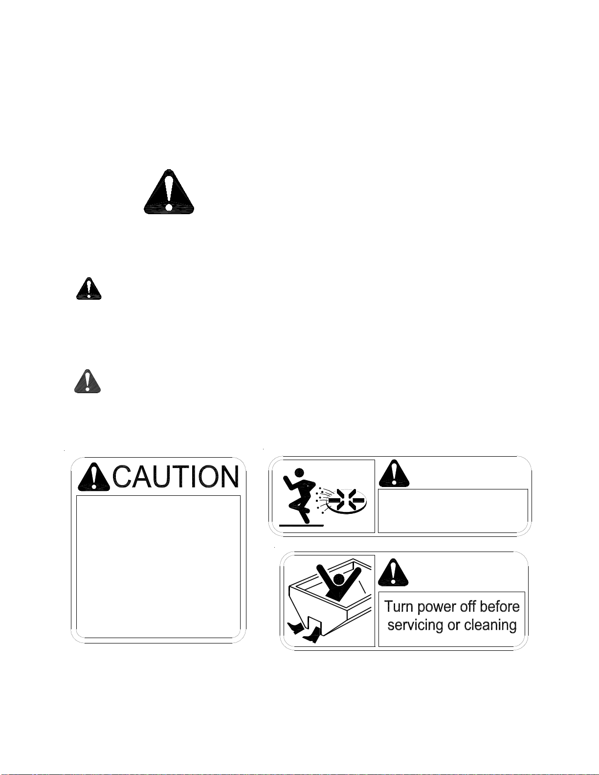
WARNING!
1. As with all power equipment, safety is the number
oneconcern.
2. Do not operate this equipment until you fully
understandhowitfunctions.
3. Before starting engine, be sure that no one is near
the rear of the unit and that no one is inside the unit!
4. Donotstarttheengineorengage the conveyor
(which is interconnected to the spinner) until
everyoneisclearfrommovingpartsandflying
materialfromthespinner.
A. ON/Off Systempoweractivated(readyto
start).Spreaderenginenotrunning.
Spreaderconveyor isnotengaged.
B. START(EngineOnly)
1. Openfuelshut off valveonengine.
CHOKE (Coldengine.) Holddownfor
5 seconds to move the throttle
actuator to the choke position.
NOTE: Choking a warm engine may not be
necessary.
4.START Hold down buttonuntil engine starts.
5.TURTLE Decreases throttle speed - adjust as
engine warms up. Will stop the
chokefunction.
RABBIT Increasesthrottle speed.
C. TOENGAGESPREADERCONVEYOR
1.CONVEYOR PushCONVEYOR switch only after
you are sure no one is in the hopper
ornearthespinner!
D. TOCONTROLCONVEYORSPEED
1.RABBIT Hold RABBIT to increasespeed.Note
DO NOT hold switch in HI position
afterthedesiredRPM is achieved or
you will choke and/or stall the
engine.
2.TURTLE Hold TURTLE to decreasespeed.
E. TODISENGAGESPREADERCONVEYOR
1.CONVEYOR Push conveyor button.
Stop
Start
Choke /
Throttle Fast
Throttle Slow
Conveyor
SPREADEROPERATION
Wireless Throttle Control Button Functions
(Sequenceof Operations)