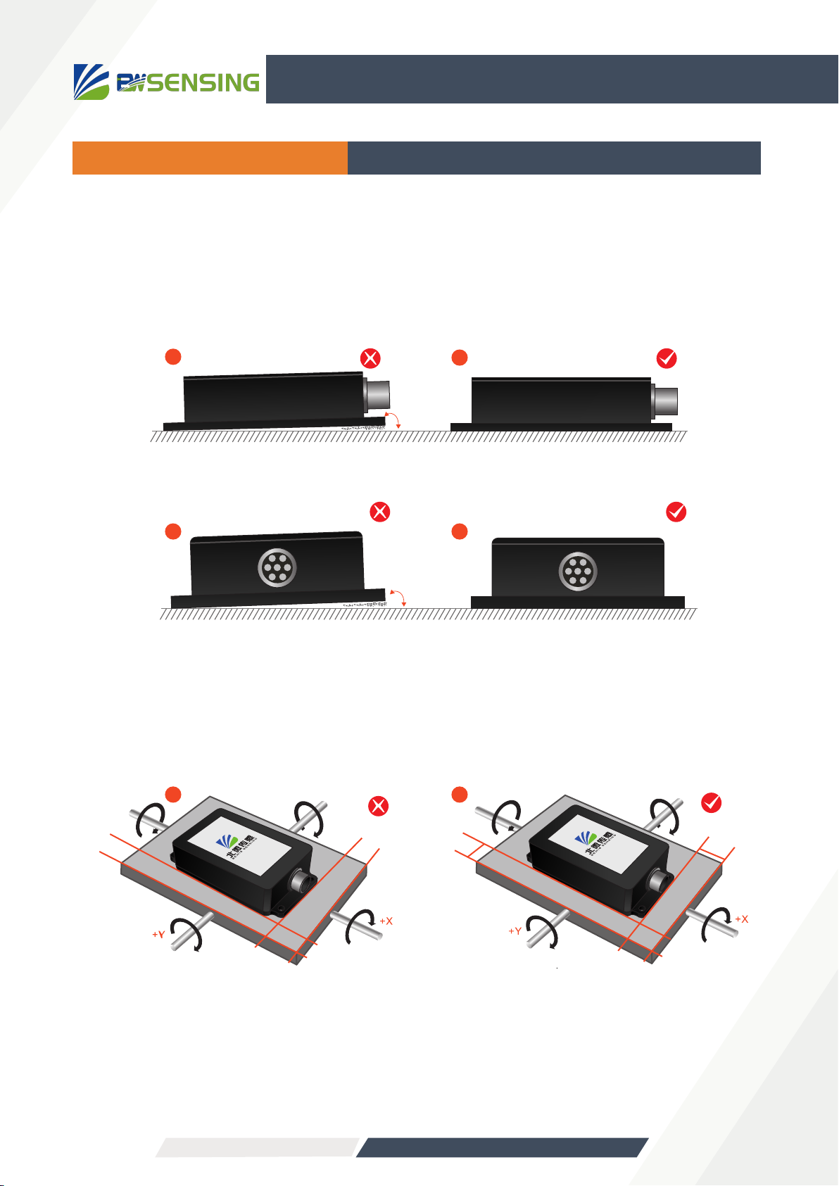
BW-VG425
High Precision CAN bus Dynamic Inclination Sensor
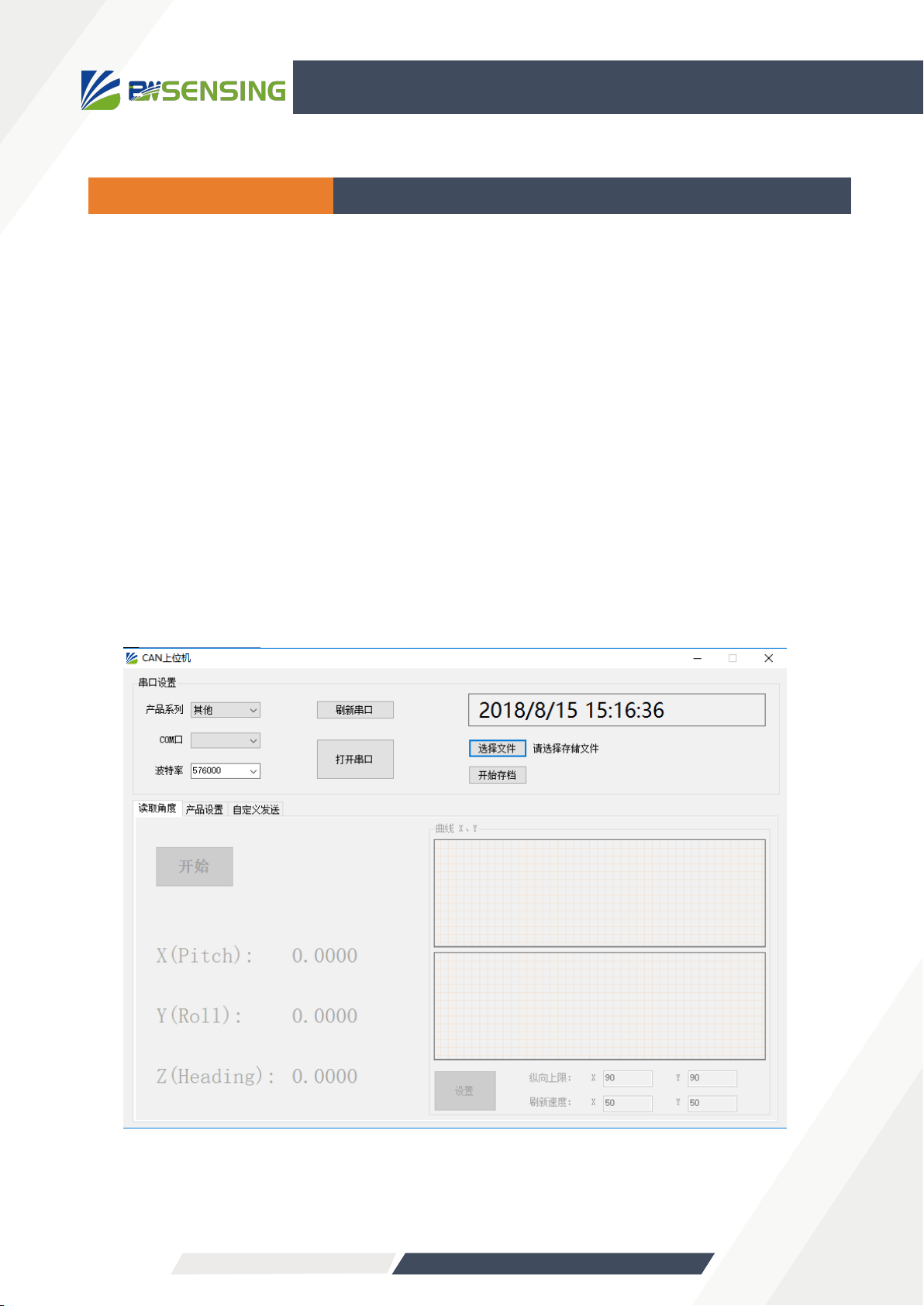
Protocol
The CAN includes 8 bytes, and add 0 to it if the data byte is not enough . Sending the first byte 0x40 indicates
a write command, returning the first byte 0x40 indicates that the write was successful. The ID is the CAN
communication node number.
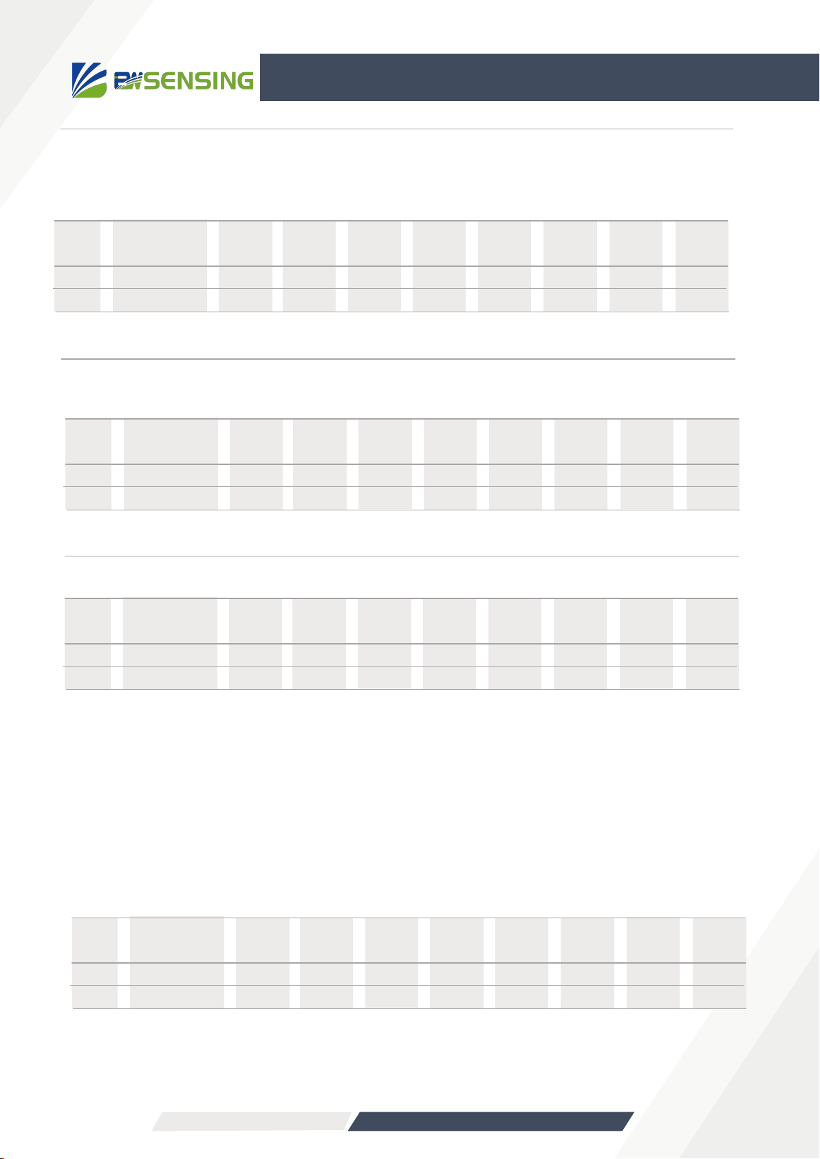
2)Set the CAN baud rate:
Note: The fifth byte (Baud) is 0x01, 0x02, 0x03, 0x04, 0x05, 0x06.
0x01 represents the setting baud rate of 500K bps
0x02 represents the setting baud rate of 250K bps
0x03 represents the setting baud rate of 125K bps
0x04 represents the setting baud rate of 100K bps
0x05 represents the setting baud rate of 50K bps
0x06 represents the setting baud rate of 25K bps
The default baud rate is 125K bps. After modifying the baud rate, the sensor needs to be powered on
again, and the baud rate modification can be successful. The lower the baud rate, the shorter the
communication distance. The communication distance can reach more than 1000m at 25K bps.
3)Set relative \ absolute zero
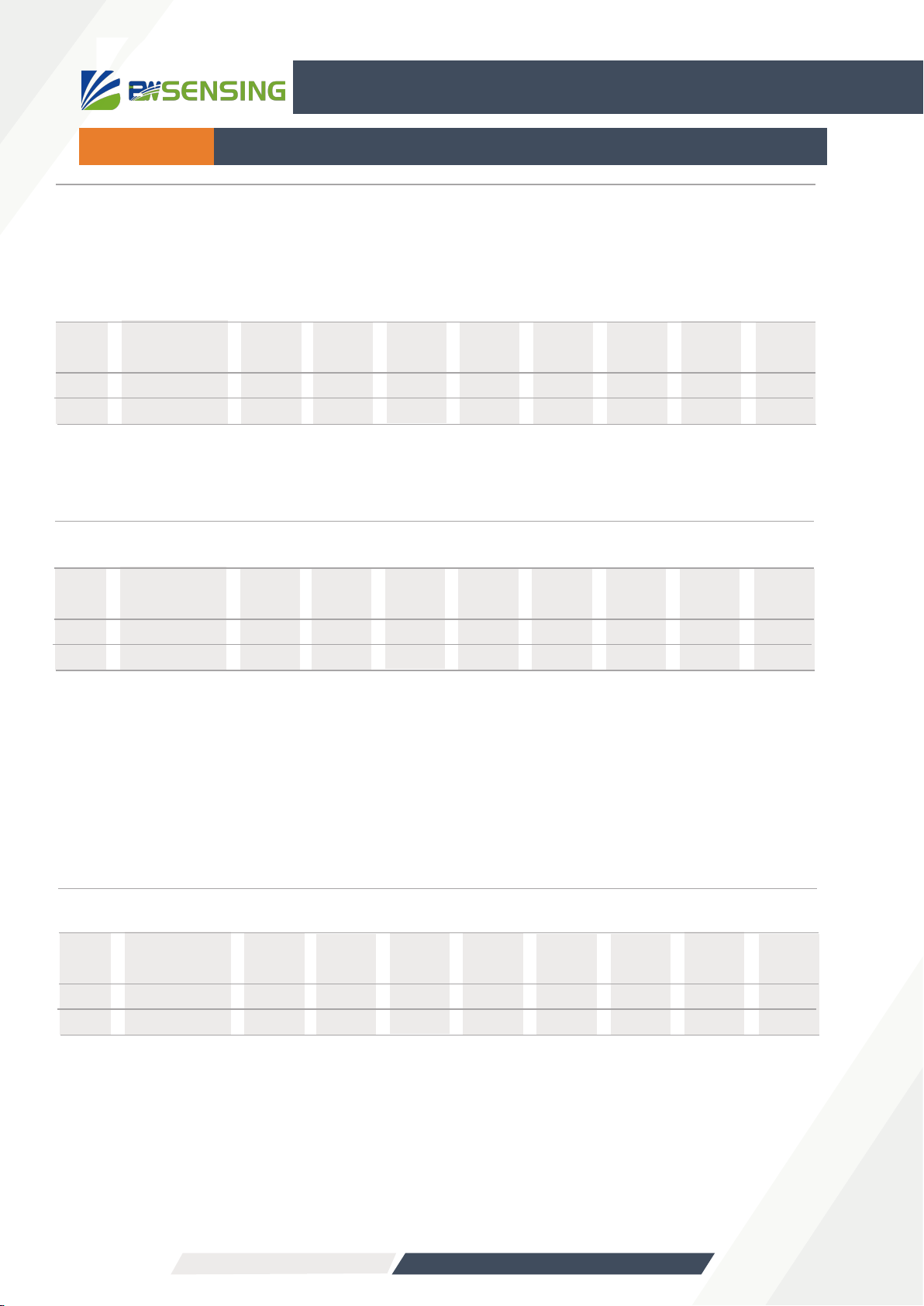
1)Modify node number:
(ID=0x01~0x7F),The default node number (ID) is 0x05
Send
Respond
CAN-ID
0x600+0x05
0x580+0xID
First
byte
0x40
0x40
Second
byte
0x10
0x10
Third
byte
0x10
0x10
Fourth
byte
0x00
0x00
Fifth
byte
ID
ID
Sixth
byte
0x00
0x00
Seventh
byte
0x00
0x00
Eighth
byte
0x00
0x00
Note: If the controller sends CAN-ID=0x600+0x05 (default), send data: 40 10 10 00 10 00 00 00,The sensor returns CAN-
ID=0x580+0x10 and returns data: 40 10 10 00 10 00 00 00,
The CAN-ID is 0x590 (0x580+0x10), indicating that the ID modification is successful. At this time, when sending other
naming, the CAN-ID needs to be changed to 0x610 to be successfully transmitted.
Note: The 5th byte Type is 0x00, 0x01. 0x00 means set to absolute zero, 0x01 means set to relative zero,
After setting the zero point, you need to enter the save command to set the success (the default is
absolute zero).
Send
Respond
CAN-ID
0x600+0x05
First
byte
0x40
Second
byte
0x20
Third
byte
0x10
Fourth
byte
0x00
Fifth
byte
Baud
Sixth
byte
0x00
Seventh
byte
0x00
Eighth
byte
0x00
Send
Respond
CAN-ID
0x600+0x05
0x580+0x05
First
byte
0x40
0x40
Second
byte
0x05
0x05
Third
byte
0x10
0x10
Fourth
byte
0x00
0x00
Fifth
byte
Type
0x00
Sixth
byte
0x00
0x00
Seventh
byte
0x00
0x00
Eighth
byte
0x00
0x00
Bewis Sensing Technology LLC www.bwsensing.com Tel:+86 189 0617 7922