BW SENSING BW-AH525 Series User manual

B
BW-AH525Serials
High precision CAN bus AHRS
Technical Manual

BW-AH525 Attitude and Heading Reference System (AHRS) is a high performance, low cost inertial
measurement device that measures the attitude parameters (roll and pitch), angular velocity, acceleration
information and heading angle of the dynamic carrier. The attitude and angular velocity deviations are
estimated by a 6-state Kalman filter with appropriate gain, which is suitable for dynamic measurement of
navigation and positioning. The BW-AH525 uses high-quality and reliable MEMS accelerometers, gyroscopes
and magnetometers, and guarantees measurement accuracy through algorithms. Meanwhile, the seal design
and strict process ensure that the dynamic parameters of the carrier such as the angular velocity、acceleration
and attitude can be accurately measured under harsh conditions. Through various compensations such as
nonlinear compensation, quadrature compensation, temperature compensation and drift compensation, the
error source of BW-AH525 can be greatly eliminated, and the product accuracy level can be improved.The BW-
AH525 is equipped with digital interface that can be easily integrated into the user's system.
Introduction
Feature
●Nonlinear compensation,
quadrature compensation
●Dynamic static measurement
●Special offset tracking algorithm
eliminates drift
●Gyro drift compensation
●Heading accuracy 0.3°
Application
●CAN bus output
●temperature range:-40℃~
+85℃,temperature compensation technical
●High performance Kalman filter algorithm
●Product size: L103.8 x W55.4 x H26(mm)
●Satellite tracking
●High voltage tower monitoring
●Aerial work vehicle
●ROV underwater robot
navigation
●Drilling equipment measurement and
control
●Ocean Tester
●Robot control
●Unmanned aerial vehicle
BW-AH525
High precision CAN bus AHRS
Bewis Sensing Technology LLC
www.bwsensing.com TEL:0510-85737158

Voltage
Working current
Operating temperature
Storage temperature
9-35V DC
30mA(40mA max)
-40~85℃
-55~100℃
Resolution: The smallest change in the value that the sensor can detect and resolve
within the measurement range.
Accuracy: The root mean square error of the actual angle and the measured angle of the
sensor multiple times (≥16 times).
Introduction
Electrical
Specifications
Performance
Specifications
Attitude parameters
Heading parameters
Physical characteristics
Interface characteristics
Environment
Pitch Accuracy
Roll accuracy
Resolution
Slant Range
Heading Accuracy
Resolution
Size
Weight
CAN
Start Delay
Maximum Output Rate
Serial Communication Rate
Digital Output Format
Vibration Resistance 2000g
Binary high performance protocol
2400-115200 Baud rate
50Hz
<3s
150g
L103.8 x W55.4 x H26(mm)
0.01°
0.7°(Pitch<80°)
0.5°(Pitch<60°)
0.3°(Pitch<40°)
Pitch ± 90º, Roll ± 180º
0.01°
0.1°(RMS,dynamic)0.01(RMS,Static)
0.1°(RMS,dynamic)0.01°(RMS,Static)
Output form
Bewis Sensing Technology LLC www.bwsensing.com TEL:0510-85737158
BW-AH525
High precision CAN bus AHRS

Connector
Protection level
Shell material
Installation
Aviation joint (line length 1.5m)
IP67
Magnesium alloy oxidation
Three M4 screws
Mechanical
Characteristic
Package size
Bewis Sensing Technology LLC www.bwsensing.com TEL:0510-85737158
BW-AH525
High precision CAN bus AHRS
Size:L103.8*W55.4*H26(mm)
Bare plate
product size
Size:L68*W48*H12(mm)
Note: ±1mm error for length and width dimensions, please refer to actual size.
104
96
36
55
86
Top view
4
10
26
Aviation joint :116
Metal joint:105
86
孔Φ 2mm
43
63
68
48
15
5

Product installation
The correct installation method can avoid measurement errors, and the following points should
be taken when installing the sensor:
First of all, to ensure that the sensor mounting surface is completely close to the measured
surface, the measured surface should be as horizontal as possible, and there should be no angle
shown in Figure A and Figure C. The correct installation method is shown in Figure B and Figure D.
Measured surface
The mounting
surface is
uneven and
produces an
angle
Measured surface
The mounting
surface is
uneven and
produces an
angle
C D
Measured surface Measured surface
AB
Secondly, the bottom edge of the sensor and the axis of the object to be measured cannot be generated at an
angle as shown in Figure E. The bottom edge of the sensor should be kept parallel or orthogonal to the axis of
rotation of the object to be measured. This product can be installed horizontally or vertically (vertical installation
requires customization), and the correct installation method is shown in Figure F.
Finally, the mounting surface of the sensor and the surface to be measured must be fixed, the
contact is flat, and the rotation is stable. The measurement error caused by acceleration and vibration
should be avoided.
Bewis Sensing Technology LLC www.bwsensing.com TEL:0510-85737158
BW-AH525
High precision CAN bus AHRS

Bewis Sensing Technology LLC
www.bwsensing.com TEL:0510-85737158
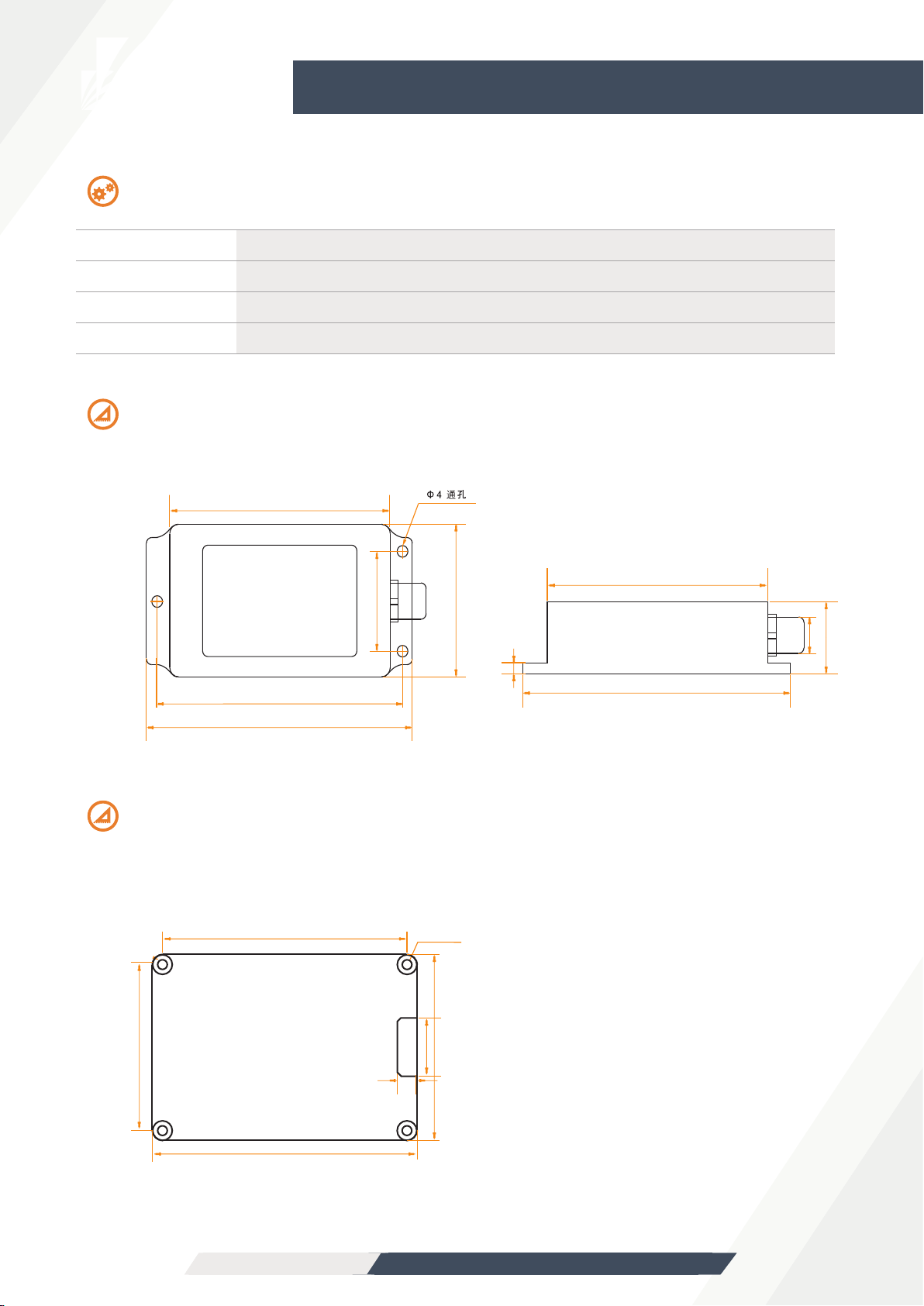
Measurement installation
The azimuth reference system has been calibrated at the factory. In places where the influence of the
magnetic field environment is small, it is not necessary to perform environmental calibration when using
it, and it can be used directly. During actual use, it is recommended to perform calibration.
Azimuth calibration steps:
Method 1 - Plane calibration:
1. Connect the product to the system and place the product in a horizontal state;
2. Open the CAN debugging tool and send 605 40 11 10 00 00 00 00 00;
3. Rotate the product in the horizontal plane (with the pitch and roll angles within +-5°) around the
z-axis (the z-axis is vertical) and rotate 2-3 turns,the rotation process is as slow as possible and
rotates at a constant speed. The time of one rotation is controlled between 10 seconds and 15
seconds.
4. Rotate the compass around the x-axis or y-axis. The rotation can be performed at a slow speed
and near-uniform rotation. Rotate 2-3 turns around each axis for a period of about 15 seconds.
5. Complete the calibration and send 605 40 12 10 00 00 00 00 00 to save the calibration.
Method 2 - Multi-faceted calibration:
1. Fix the electronic compass in the use environment, and try not to carry magnetic items such as
keys and mobile phones during calibration;
2. Place the compass in a horizontal state (within ±5 degrees);
3. Send the following calibration command in hexadecimal format: 605 40 08 10 00 00 00 00 00;
4. The product is placed horizontally, face up (pitch and roll are within 0±5 degrees), myopia
rotates at a uniform speed for one week, and rotation takes more than ten seconds.
5. The product is placed horizontally with the mounting surface facing up (within 0±5 degrees of pitch
and 180±5 degrees of rolling). The myopia rotates at a uniform speed for one week, and it takes about
10 seconds to rotate one week.
6. The product is placed in a vertical state with the smooth side of the casing facing down (within 0±5
degrees of pitch and 90±5 degrees of rolling). The myopia rotates at a uniform speed for one week,
and it takes about 10 seconds to rotate one week.
7. The product is placed in a vertical position, and the other smooth side of the casing faces downward
(within 0±5 degrees of pitch and within -90±5 degrees of rolling). The approximately rotates at a
uniform speed for one week, and it takes about 10 seconds to rotate one week;
Where 4.5.6.7 steps can be exchanged;
8. After the four faces have been rotated, send the hexadecimal command 605 40 09 10 00 00 00 00 00
to save the calibration and return to 585 40 09 10 00 XX 00 00 00. Where XX represents the calibration
error coefficient, the smaller the value, the better, less than 10 is ideal, and FF indicates calibration
failure;
9. Calibration is complete.
Clear calibration data command: 605 40 13 10 00 00 00 00 00
BW-AH525
High precision CAN bus AHRS

Bewis Sensing Technology LLC
www.bwsensing.com TEL:0510-85737158
Debugging software
Since there is a dedicated CAN receiving device for data communication with CAN interface products,
the software is a CAN acquisition device.
The software used is not the same, so there is no corresponding software. Let's take the CAN receiver
module and product communication adopted by our company as an example:
Configure the CAN baud rate and parameters as follows:
The receiving and sending areas are set as follows:
BW-AH525
High precision CAN bus AHRS

Bewis Sensing Technology LLC
www.bwsensing.com TEL:0510-85737158
BW-AH525
High precision CAN bus AHRS
Protocol
The CAN includes 8 bytes, and the data byte is not enough to be followed by 0. Sending the first byte 0x40
indicates a write command, and returning the first byte 0x40 indicates that the write was successful. The ID is
the CAN communication node number. Default: CAN baud rate is 125K, 100HZ auto output, node number is
05.
2)Set the CAN baud rate:
Note: The fifth byte (Baud) is 0x01, 0x02, 0x03, 0x04, 0x05, 0x06. 0x01 represents the setting baud rate of 500K bps,
0x02 represents the set baud rate of 250K bps,
0x03 represents the set baud rate of 125K bps,
0x04 represents the set baud rate of 100K bps,
0x05 represents the set baud rate of 50K bps,
0x06 represents the set baud rate of 25K bps,
The default baud rate is 125K bps. After modifying the baud rate, the sensor needs to be powered on again,
and the baud rate modification can be successful.
3)Set relative \ absolute zero:
1)Modify the node number:
(ID=0x01~0x7F),The default node number (ID) is 0x05
send
answer
CAN-ID
0x600+0x05
0x580+0xID
First
byte
0x40
0x40
Second
byte
0x10
0x10
Third
byte
0x10
0x10
Fourth
byte
0x00
0x00
Fifth
byte
ID
ID
Sixth
byte
0x00
0x00
Seventh b
byte
0x00
0x00
Eighth
byte
0x00
0x00
Note: The default node number is 05 and the ID indicates the node number to be modified.
For example, if the node number is changed to 08, you need to send 605 40 10 10 00 08 00 00 00.
The return value is 588 40 10 10 00 08 00 00 00, indicating that the node has been modified to 08.
At this time, when sending other naming, you need to change the CAN-ID to 0x608 to send successfully.
There is no need to send a save command.
send
answer
CAN-ID
0x600+0x05
First
byte
0x40
Second
byte
0x20
Third
byte
0x10
Fourth
byte
0x00
Fifth
byte
Baud
Sixth
byte
0x00
Seventh
byte
0x00
Eighth
byte
0x00
send
answer
CAN-ID
0x600+0x05
Third
byte
0x10
Fourth
byte
0x00
Fifth
byte
Type
Sixth
byte
0x00
Seventh
byte
0x00
Eighth
byte
0x00
0x580+0x05 0x40 0x05 0x10 0x00 0x00 0x00 0x00 0x00
Note: The 5th byte Type is 0x00, 0x01. 0x00 means to set to absolute zero, 0x01 means the pitch and roll
angle are set to relative zero, 0x02 means the azimuth is set to relative zero, after setting the zero point,
you need to enter the save command. Can be set successfully. (Default is absolute zero)
Absolute zero: The measurement angle is based on the factory-calibrated zero point.
Relative zero: The measurement angle is zero reference to the current position.
First
byte
0x40 0x05
Second
byte

Bewis Sensing Technology LLC
www.bwsensing.com TEL:0510-85737158
BW-AH525
High precision CAN bus AHRS
4)Query relative\absolute zero:
send
answer
0x10
Fourth
byte
0x00
Fifth
byte
0x00
Sixth
byte
0x00
Seventh
byte
0x00
Eighth
byte
0x00
0x40 0x05 0x10 0x00 Type 0x00 0x00 0x00
Note: The 5th byte Type is 0x00, 0x01. 0x00 is represented as absolute zero, and 0x01 is represented as
relative zero.
First
byte
0x40
Second
byte
0x0d
Third
byte
5)save
send
answer
Note: After some parameters are modified, you need to send a save command to take effect.
CAN-ID
0x600+0x05
0x580+0x05
6)Read each attitude angle
CAN-ID
0x600+0x05
0x580+0x05
send
answer
First
byte
0x40
SX
Second
byte
0x04
XX
Third
byte
0x10
xx
Fourth
byte
0x00
SX
Fifth
byte
Sixth
byte
0x00
yy
Seventh
byte
0x00
BB
Eighth
byte
0x00
Bb
0x00
YY
Note: The read angle command needs to be valid in the answer mode.
The pitch angle is represented by a 3-byte BCD code (1~3 bytes). The highest bit S is a sign bit, 0-positive; 1-negative, uppercase
X is an integer bit, lowercase x is a decimal place; roll angle is 3 The BCD code of the byte indicates (4~6 bytes) that the highest bit
S is a sign bit, 0-positive; 1-negative, uppercase Y is an integer bit, lowercase y is a decimal place; azimuth is 2 bytes BCD The code
indicates (7~8 bytes) unsigned bits, uppercase B is an integer bit, and lowercase b is a decimal place;
For example, if the returned data is 585 00 12 34 10 12 34 26 35, it means that the pitch angle is +12.34 degrees, the roll angle is
-12.34 degrees, and the azimuth angle is 263.5 degrees.
CAN-ID
0x600+0x05
0x580+0x05
0x10
Fourth
byte
0x00
Fifth
byte
0x00
Sixth
byte
0x00
Seventh
byte
0x00
Eighth
byte
0x00
0x40 0x0a 0x10 0x00 0x00 0x00 0x00 0x00
First
byte
0x40
Second
byte
0x0a
Third
byte
7)Set output mode
CAN-ID First
byte
Second
byte
Third
byte
Fourth
byte
Fifth
byte
Sixth
byte
Seventh
byte
0x600+0x05
0x580+0x05
0x40
0x40
0x0c
0x0c
0x10
0x10
0x00
0x00
mode
mode
0x00
0x00
0x00
0x00
0x00
0x00
Note: The fifth byte mode is 0x00, 0x01, 0x02, 0x03, 0x04, 0x05, 0x06. Where 0x00 represents the answer mode,
0x01:5Hz Data Rate, 0x02:10Hz Data Rate,
0x03:20Hz Data Rate,0x04:25Hz Data Rate,
0x05:50Hz Data Rate,0x06:100Hz Data Rate(default),
5Hz Data Rate means 5 times of data is output automatically every second. Sending other names should
be done in Q&A mode (automatic mode is to continuously output the current angle of the axis according
to the specific frequency. In the answer mode, it is easier to see other commands return. value).
Eighth
byte
send
answer

Bewis Sensing Technology LLC
www.bwsensing.com TEL:0510-85737158
BW-AH525
High precision CAN bus AHRS
10)Reading magnetic field value
CAN-ID
0x600+0x05
0x580+0x05
send
answer
First
byte
0x40
0x55
Second
byte
0x55
0x00
Third
byte
0x10
AA
Fourth
byte
0x00
AA
Fifth
byte
Sixth
byte节
0x00
BB
Seventh
byte
0x00
CC
Eighth
byte
0x00
CC
0x00
BB
Note: The X-axis magnetic field value is (AAAA-5000)/5000.
The Y-axis magnetic field value is (BBBB-5000)/5000.
The Z-axis magnetic field value is (CCCC-5000)/5000.
For example, when the received data is 585 55 00 64 85 35 07 50 16, the data on the X-axis is
(6485-5000)/5000=0.297G, and G is Gaussian.
8)Reading angular velocity
Note: The angular velocity of the X axis is (AAAA-5000)/10.
The angular velocity of the Y axis is is (BBBB-5000)/10,
The angular velocity of the Z axis is is (CCCC-5000)/10,
For example, when the received data is 585 50 00 50 12 50 07 50 11, the data on the X-axis is (5012-5000)/10 = 1.2°/s, and
so on.
9)Read acceleration
CAN-ID
0x600+0x05
0x580+0x05
send
answer
First
byte
0x40
0x50
Second
byte
0x50
0x00
Third
byte
0x10
AA
Fourth
byte
0x00
AA
Fifth
byte
Sixth
byte
0x00
BB
Seventh
byte
0x00
CC
Eighth
byte
0x00
CC
0x00
BB
CAN-ID
0x600+0x05
0x580+0x05
send
answer
First
byte
0x40
0x54
Second
byte
0x54
0x00
Third
byte
0x10
AA
Fourth
byte
0x00
AA
Fifth
byte
Sixth
byte
0x00
BB
Seventh
byte
0x00
CC
Eighth
byte
0x00
CC
0x00
BB
Note: The X-axis acceleration is (AAAA-5000)/2500.
The y-axis acceleration is (BBBB-5000)/2500,
The Z-axis acceleration is (CCCC-5000)/2500,
For example, when the received data is 585 54 00 51 05 49 72 25 79,
The data for the X-axis is (5105-5000)/2500 = 0.042g, where g is the Earth's gravitational
acceleration.
11)Select automatic output data
CAN-ID First
byte
Second
byte
Third
byte
Fourth
byte
Fifth
byte
Sixth
byte
Seventh
byte
0x600+0x05
0x580+0x05
0x40
0x40
0x53
0x53
0x10
0x10
0x00
0x00
mode
mode
0x00
0x00
0x00
0x00
0x00
0x00
Eighth
byte
send
answer

Bewis Sensing Technology LLC www.bwsensing.com TEL:0510-85737158
BW-AH525
High precision CAN bus AHRS
Note: The data of the mode bit output is selected, where 0x00: automatic output attitude angle (default)
0x01: Automatic output acceleration
0x02: Automatic output angular velocity
0x03: Automatic output magnetic field value
0x04: Automatic output attitude angle, acceleration, angular velocity
0x05: automatic output attitude angle, acceleration, angular velocity,
magnetic field value
12)Set the magnetic declination
send
answer
CAN-ID
0x600+0x05
First
byte
0x40
Second
byte
0x06
Fourth
byte
0x00
Fifth
byte
SY
Sixth
byte
Yy
Seventh
byte
0x00
Eighth
byte
0x00
Note: The magnetic declination is represented by a 2-byte BCD code (5~6 bytes). The highest bit S is a sign bit, 0-
positive; 1-negative, uppercase Y is an integer bit, and lowercase y is a decimal place.
Third
byte
0x10
0xXHXL+0x05
13)Set the standard CAN-ID address
send
answer
CAN-ID
0x600+0x05
First
byte
0x40
Second
byte
0x70
Fourth
byte
0x00
Fifth
byte
XX
Sixth
byte
0x00
Seventh
byte
0x00
Eighth
byte
0x00
Note: XX is 00, 01.00 represents the standard ID (11-bit) type, and 01 represents the extended ID (27-bit) type. The
default is standard.
Third
byte
0x10
14)Set the standard CAN-ID address
send
answer
CAN-ID
0x600+0x05
First
byte
0x40
Second
byte
0x71
Fourth
byte
0x00
Fifth
byte
XH
Sixth
byte
XL
Seventh
byte
0x00
Eighth
byte
0x00
Note: The standard CAN-ID defaults to 0X580+05 and the maximum value cannot exceed 7FF. The modification here is
that 580,05 in 0X580+05 can be modified by modifying the node number in the previous section. After powering up, the
CAN-ID will become 0x XHXL+0x05.
For example, if you send data: 605 40 71 10 00 01 23 00 00, the CAN-ID becomes 123+5=128 after power-off then
power-on.
Third
byte
0x10
0xXHXL+0x05
15)Set the extended CAN-ID address
When setting the extended CAN-ID address, you need to split the address into two segments, first sending a high
16 address, and then lowering the 16-bit address. Re-power on CAN-ID
It becomes the changed address (the CAN-ID received here does not need to add the node number). The
maximum value cannot exceed 7FFFFFF. The default is 0x 18fa0216.

Bewis Sensing Technology LLC
www.bwsensing.com TEL:0510-85737158
BW-AH525
High precision CAN bus AHRS
ⅠSet the extended CAN-ID high 16-bit address
send
answer
CAN-ID
0x600+0x05
First
byte
0x40
Second
byte
0x72
Fourth
byte
0x00
Fifth
byte
XH
Sixth
byte
XL
Seventh
byte
0x00
Eighth
byte
0x00
0x10
Third
byte
Note: The extended CAN-ID high 16-bit address cannot be greater than 7FF.
ⅡSet the extended CAN-ID low 16-bit address
send
answer
CAN-ID
0x600+0x05
First
byte
0x40
Fourth
byte
0x00
Fifth
byte
XH
Sixth
byte
XL
Seventh
byte
0x00
Eighth
byte
0x00
0x10
Third
byte
Note: The extended CAN-IDd low 16-bit address cannot be greater than FFFF.
For example, if you send 605 40 72 10 00 01 23 00 00, 605 40 73 10 00 45 67
00 00 twice, the CAN-ID will be 01234567 after power-off.
Second
byte
0x73
16)Set Kalman filter parameters
CAN-ID
0x600+0x05
0x580+0x05
send
answer
First
byte
0x40
0x00
Second
byte
0x80
XX
Third
byte
0x10
YY
Fourth
byte
0x00
YY
Fifth
byte
Sixth
byte
YY
0x00
Seventh
byte
YY
0x00
Seventh
byte
0x00
0x00
XX
0x00
Note: Set the parameter to XX.YYYY and save it automatically after setting. The parameter range is
1.0~1.5 (excluding 1.0 and 1.5).
For example: Send 605 40 80 10 00 01 00 02 00, then set the Kalman filter parameter to 1.0002 and save it
automatically.
17)Query Kalman filter parameters
CAN-ID
0x600+0x05
0x580+0x05
send
answer
First
byte
0x40
0x00
Second
byte
0x81
XX
Third
byte
0x10
YY
Fourth
byte
0x00
YY
Fifth
byte
Sixth
byte
0x00
0x00
Seventh
byte
0x00
0x00
Seventh
byte
0x00
0x00
0x00
0x00
For example: return 585 00 01 00 02 00 00 00 00, then the Kalman filter parameter is 10002.

Ordering Information
Executive standard
●Enterprise Quality System Standard: ISO9001:2008 Standard (Certificate
No.:10114Q16846ROS)
●CE certification (certificate number: 3854210814)
●ROHS (certificate number: SO81426003)
●GB/T 191 SJ 20873-2003 General specifications for tiltmeters and spirit
levels
●GBT 18459-2001 sensor main static performance index calculation
method
●JF 1059-1999 Evaluation and Expression of Measurement Uncertainty
●GBT 14412-2005 mechanical vibration and shock mechanical
installation of accelerometer
●General requirements for GJB 450A-2004 equipment reliability
●Quality control of key parts and important parts of GJB 909A
●GJB 899 Reliability Qualification and Acceptance Test
●GJB 150-3A high temperature test
●GJB 150-4A low temperature test
●GJB 150-8A rain test
●GJB 150-12A dust test
●GJB 150-16A vibration test
●GJB 150-18A impact test
●GJB 150-23A Tilt and Swing Test
●GB/T 17626-3A RF electromagnetic radiation immunity test
●GB/T 17626-5A surge (hit) impulse immunity test
●GB/T 17626-8A power frequency magnetic field immunity test
●GB/T 17626-11A voltage dips, short interruptions and voltage changes
immunity
Bewis Sensing Technology LLC www.bwsensing.com TEL:0510-85737158
BW-AH525
High precision CAN bus AHRS
Product number Product number Package condition
BW-AH525-CAN CAN IP67 package / Aviation joint

BW-AH525
High precision CAN bus AHRS
Wuxi Bewis Sensing Technology LLC
Address: Building 30, No. 58 Xiuxi Road,
Binhu District, Wuxi City,China
Hotline: 400-618-0510
Tel: +86 510 85737178-801
Email: [email protected]
Website: www.bwsensing.com
This manual suits for next models
1
Table of contents
Other BW SENSING Accessories manuals