BWT PEARL HPT 09 User manual

Instructions Manual
EN
BWT PEARL HPT 09
BWT PEARL HPT 12
BWT PEARL HPT 15
BWT PEARL HPT 18
BWT PEARL HPT 20

- 2 -
BWT Group
BWT Pearl HPT 09/12/15/18/20
R&D Department
France, 04/2022
EN-SWIMING POOL HEAT PUMP
Declaration of conformity
Guidelines – Harmonised standards
We hereby declare under our sole responsibility that this product complies with the relevant guidelines
SAA:
SAFETY EN 60335-1:2012/A2:2019 EN 60335-2-40:2003/A13:2012 EN 62233:2008
EMC EN 55014-1:2017 EN 61000-3-11:2000 EN 55014-2:2015 EN 61000-3-3:2013
EN 61000-3-12:2011 EN 61000-3-2:2014
NOISE 200/14/CE
HP Models:
Other normative documents Person authorised to manage technical documentation
RoHS 2011/65/EU
WEEE 2012/19/EU
Processing by individuals of electronic appliances reaching the end of their lifespan:
The symbol depicting a barred wastebin that features on the main parts constituting the product indicates that it must not be
discarded alongside household waste. It must be brought to an adequate collection point where electronic appliances are
recycled (information available from your local waste treatment service). This product contains potentially hazardous substanc-
es.
DELIVERY AND TRANSPORT
• When you have unpacked the HP, please check the content to report any damage. Please also check that the pressure reading on the pressure gauge corre-
sponds to the outside temperature, as different values might indicate a leak, depending on the measured outdoor temperature, as different values might indicate
a leak.
• The HP should always be stored and transported in a vertical position, on a pallet and inside its original packaging.
• Transporting and/or storing the HP horizontally will void the guarantee.
DIMENSIONS
Models A B C D E
All Models 704 mm 802 mm 177 mm 217 mm 243 mm

- 3 -
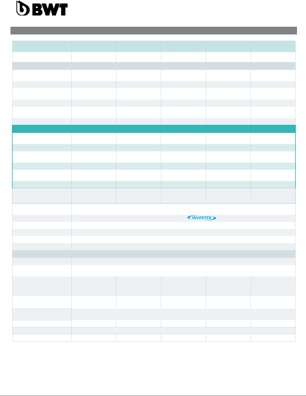
TECHNICAL SPECIFICATIONS
Models BWT PEARL HPT09 BWT PEARL HPT12 BWT PEARL HPT15 BWT PEARL HPT18 BWT PEARL HPT20
Recommended pool size
(Mai to septembre with a cover) 35-45 m³ 45-55 m³ 55-70 m³ 70-85 m³ 85-105 m³
Air 26°C / Water 26°C / 80%HR
Capacity in MAX Mode 9,5 kW 12,8 kW 15,3 kW 18,2 kW 20,1 kW
COP MAX Mode 6,3 6,2 6,3 6,2 6,1
Capacity in ECO Mode 9,5 ~ 3,2 kW 12,8 ~ 3,5 kW 15,3 ~ 3,9 kW 18,2 ~ 4,2 kW 20,1 ~ 5,5 kW
COP ECO Mode 10,8 ~ 6,3 10,8 ~ 6,2 10,8 ~ 6,3 11,2 ~ 6,2 10,8 ~ 6,1
Capacity in SILENT 3,2 kW 3,5 kW 3,9 kW 4,2 kW 5,5 kW
COP SILENT 10,8 10,8 10,8 11,2 10,8
Air 15°C / Water 26°C / 70%HR**
Capacity in MAX Mode 6,9 kW 9,1 kW 11,0 kW 12,7 kW 14,5 kW
COP MAX Mode 4,7 4,6 4,7 4,6 4,5
Capacity in ECO Mode 6,9 ~ 3,5 kW 9,1 ~ 3,9 kW 11,0 ~ 5,0 kW 12,7 ~ 7,1 kW 14,5 ~ 7,0 Kw
COP ECO Mode 6,6~4,7 7,8~4,6 7,7~4,7 7,9~4,6 7,9~4,5
Capacity in SILENT 3,5 kW 3,9 kW 5,0 kW 7,1 kW 7,0 kW
COP SILENT 6,4 6,6 6,5 6,6 6,6
Noise level mini-maxi (at 10m)
according to EN ISO 3744:2010 19 ~ 28 dB(a) 20 ~ 29 dB(a) 21 ~ 30 dB(a) 22 ~ 31 dB(a) 23 ~ 32 dB(a)
Operating temperature -10°C -> 38°C
Compresseor type 2D Technology Full DC
Expansion valve Electronic
Heat Exchanger Optimal Twist
Casing ABS treated against UV
Refrigerant R32
Installation
Water connection 1,5" / 50 mm
Power 230V / 1~+N / 50 Hz
Nominal current (Maximum
Current) 6,0 A (9 A) 7,9 A (13,0 A) 9,8 A (14,0 A) 11,5 A (16,0 A) 14,2A(17,0A)
Max power input (Air 26°C) 1,9 kW 2,6 kW 2,9 kW 3,8 kW 4,2 kW
Dimensions (L x l x h) Diameter 680 mm * height 775 mm
Water flow 3 m³/h 4 m³/h 5 m³/h 5 m³/h 6 m³/h
Water pressure drop 64 kPa
Weight net (gross) 45 kg (65 kg) 47 kg (69 kg) 49 kg (70kg) 57 kg (76 kg) 59 kg (76 kg)

- 4 -
Installation (site, type of support, necessary space) P. 19
Hydraulic connection P. 20
Electrical connection P. 20
Immersion and starting of HP P. 22
Use P. 22
Settings P. 23
General use P. 23
Regulation (Electronic controller) P. 24
Mobile application : BWT Inverter P. 25
Controller state table P. 26
Maintenance P. 27
Wintering P. 27
Recycling the HP P. 28
After-sales technical Departement P. 28
CONTENTS

- 5 -
This symbol indicates that the device uses R32, a coolant featuring a low combustion speed.
This symbol indicates that a maintenance technician must handle this equipment according to the operating manual.
This symbol indicates that the operating manual should be read attentively prior to use.
WARNING: In normal conditions, a suitable HP can heat the water of the pool by 1°C to 2°C per day.
It is therefore quite normal not to feel a temperature difference at the outlet of the circuit when the HP is operating. A heated pool should be covered to prevent heat losses.
The appliance is designed to be used in a swimming pool as described in standard NF-EN-16713.
• Failure to comply with the warnings could cause damage to the swimming pool equipment as well as severe injuries or death.
• Only a qualied person possessing the adequate technical skills (electricity, hydraulic, refrigeration) is authorised to undertake maintenance operations or repairs on the
device. A qualied technician working on the device must use/wear personal protective equipment (safety goggles, protection gloves, etc...) to avoid all risk of injury arising
during work on the device.
• Prior to any intervention on the device, ensure that it is powered down and has undergone the lockout-tagout procedure.
• The device is designed specically for use in swimming pools and spas; it must not be used for purposes other than the ones it was designed for.
• This device is not intended for children.
• This device is not intended to be used by persons (including children, of 8 or more) who lack experience or who suffer from physical, sensory, or mental impairment,
Except;
• if it is operated under supervision or with operating instructions issued by a person responsible for their safety; and
• if they understand the risks taken.
• Children must be supervised to ensure that they do not play with the device.
• The installation of the device should be carried out according to the manufacturer’s instructions and in compliance with local and national applicable standards. The installer
is responsible for the installation of the device and for compliance with national regulations relating to installation procedures. The manufacturer will not be liable in case of
non-compliance with the installation standards that apply locally.
• For any action other than simple maintenance operations by the user as described in this manual, the product should be maintained by a certied professional.
• Any improper installation and/or use can cause damages and severe injuries (and even death).
• Do not touch the fan or the moving parts, and do not insert objects or your ngers close to the moving parts when the device is operating. • Moving parts can
• cause severe injuries and even death.
• Do not pull on the hoses and the connections to move the machine.
WARNINGS CONCERNING ELECTRICAL APPLIANCES:
• The power supply of the device must be protected by a 30-mA security residual current protection system, as per the standards that apply in the country of installation.
• Do not use an extension to connect the device; only connect the device directly to a suitable power outlet.
• If a xed device does not feature a power cord and a plug, or any other means to disconnect from the power supply with a separation of the contacts in all the poles, enabling
total disconnection in case of a category III electrical surge, the manual will mention that the disconnection means must be integrated in the xed wiring, as per relevant
wiring rules.
• An adapted disconnection method, complying with all local and national requirements relating to category III electrical surges, and that disconnects all the poles of the supply
circuit, must be installed in the supply circuit of the device. This disconnection method is not provided with the device and should be provided by the installation technician.
• Prior to installation, check that:
• The voltage featuring on the information plate of the device matches the voltage of the power supply,
• The power supply is suitable for operating the device and has an earthing connection.
• The plug (as necessary) adapts to the plughole.
• If the power cord is damaged, it should imperatively be replaced by the manufacturer, a technician or a person qualied to ensure safety.
WARNINGS RELATING TO DEVICES CONTAINING A COOLANT:
• The coolant R32 is a coolant of category A2L, which is considered as potentially ammable.
• Do not release R32 uid into the atmosphere. This uid is a greenhouse effect uorinated gas, covered by the Kyoto Protocol, with a global warming potential (GWP) = 675 for
R32.
• The device must be stored in a well-ventilated place and kept away from ames.
• Install the unit outdoors. Do not install the unit indoors or in an outdoor area that is closed and poorly ventilated.
• To comply with the relevant standards and regulations in terms of the environment and installation procedures, and in particular with decree Nº 2015-1790 and/ or European
regulation EU 517/2014, a search for leaks of the cooling circuit must be conducted at least once a year. This operation should be carried out by a certied specialist of cool-
ing devices.
• Please keep and transmit these documents for reference throughout the lifespan of the device.

- 6 -
3m mini
INSTALLATION (SITE, TYPE OF SUPPORT, NECESSARY SPACE)
• Install the HP outdoors at more than 2 meters from the pool.
• Place the HP on the provided vibration absorbers on a surface that is stable, solid (able to bear the weight of the device) and level (prepare a concrete base if
necessary).
• Maintain 1 m (30 cm minimum) of open space in front of the vertical air intake grids (behind and on the side of the HP) and 3 m at the outlet of the fan (on the top)
of open space without any obstacles.
• Prepare sufcient space around the HP for maintenance operations.
• Prepare a water evacuation system close to the HP to protect the installation zone.
• Keep the HP out of the reach of children, insofar as possible.
The HP should never be installed:
• in an area covered by sprinkling systems, or subject to spray or running water or mud (close to a road, take into account the effects of wind),
• under a tree,
• close to a source of heat or of ammable gas,
• in an area where it would be exposed to oil, ammable gases, corrosive products, and compounds containing sulphur,
• close to equipment operating at high frequencies,
• in a place where snow is likely to accumulate,
• in a place where it could be ooded by the condensates produced by the device as it operates,
• on a surface that could transfer the vibrations to the house.
Advice: dampen the possible noise nuisance caused by your HP.
• Do not install it close to or underneath a window.
• Do not direct the outlet of the fan towards your neighbours’ property.
• Do not direct the fan outlet (cold air) towards the swimming pool.
• Install it in an open area (sound waves bounce off surfaces).
• Install a sound barrier around the HP, making sure to maintain the required distances.
• Install 50 cm of PVC piping at the water inlet and outlet of the HP.
The HP must be installed and maintained on a xed and solid basis, with the skids placed under the feet.
• For concrete, use adapted ø 8 mm lag screws tted with washers to prevent any loosening.
• For wood, use adapted ø 8 mm hexagon head screws tted with locking washers to prevent any loosening
The Ottimo HP has four feet and a condensate ex-
traction nozzle included with the product.
the condensate extraction nozzle and the four feet
must be attached before installing the machine,
using the described methode in the gure above.

- 7 -
ELECTRICAL CONNECTION
Connection of the power supply:
prior to undertaking any intervention inside the HP, it is imperative to disconnect the power supply from the HP; there is a risk of electrocution that can cause
damages, severe injuries and even death.
• Only a certied and experienced technician is authorised to conduct cabling work in an HP or to replace the power cable.
• the power supply should match the voltage featuring on the information plate of the HP.
• The HP must be connected to an earthing connection.
Electrical Installation:
To ensure safe operations and to protect the integrity of your electric installation, the HP should be connected to the electrical mains according to the following
rules:
• Upstream, the electrical mains should be protected by a 30-mA differential switch.
• The HP should be connected to a suitable class C circuit-breaker (see the table below) according to the standards and regulations in force in the country
where the system is installed.
• It is recommended to crimp the electric cables on lugs adapted to the diameter of the cable chosen before connecting them to the HP
• The power cord should be adapted to the power of the HP and the length of cable required for the installation (see the table below). The cable must be suit-
able for outdoor use.
• In the case of a three-phase system, it is imperative to follow the connection order of the phases. If phases are inverted, the compressor of the HP will not
work.
• In public spaces, the installation of an emergency stop button close to the HP is mandatory. The voltage must match the voltage mentioned on the HP.
The connections must be sized based on the power of the HP and on the installation state.
By-pass
Provided connections
(ø 50mm)
Evacuation of the condensate
Water treatment (disinfection, pH correction)
located after the HP
Bypass valve
(adjustment)
Open Valve
Half-open valve
Closed valve
From the swimming pool
Toward the swiming pool
HYDRAULIC CONNECTION
• Water quality necessary for this device: NF-EN-16713-3
• The HP is compatible with all types of water treatment. The HP must imperatively be connected by a PVC pipe of Ø 50mm to the swimming pool’s hydraulic
• circuit, after the lter and before the treatment system, regardless of its type (Cl, pH, Br metering pumps and/or electrolyser).
• Follow the hydraulic connection order (blue = water in, red = water out)
• A bypass must be installed to facilitate work on the HP.
• Before connecting the PVC pipes to the HP, make sure the circuit is clean of any work residue (stone, soil, etc.).
Connection of the condensate evacuation pack:
During operations, the HP is subject to a condensation phenomenon. This translates into a water ow, which can be more or less important depending on the
degree of humidity. To channel this ow, which can represent several litres of water per day, we recommend you install the provided condensate evacuation
pack and connect it to a suitable water evacuation circuit.

- 8 -
*Maximum cable length between heat pump and head of line protection (C curve current protection)
It is recommended to use wire terminal for better electrical contact between wire and power supply terminal.
These data are only indicative, you must ask an electrician to determine the exact data for your pool installation.
Power supply must be equipped with grounding and 30 mA differential protection.
• Use the cable-gland and the pass-throught provided inside the HP for the passage of the cable.
• As this heat pump is installed outdoors, it is mandatory to pass the cable through a protective sheath for this purpose. The power supply of the HP must be
tted with a protection device in accordance with the legislation in force.
• The electric cables must be buried at a depth of 50 cm (85 cm under a road or a path) in an electrical sheath (red corrugated). When a cable buried in a
sheath crosses another cable or a pipe (gas, water, etc.) the distance between them must be greater than 20 cm.
Automation
You have a very low voltage terminal block to which you can connect your home automation. This
is an ON / OFF dry contact. Remove the existing bridge. When your home automation opens this
contact, the machine stops and displays the message: No ow.
L: Line
N: Neutral
GND : Ground
P1 : Filtration pump relay neutral (option)
P2 : Filtration pump relay line (option)
Model Breaker Maximum cable* legnht with cable sections:
Rated current (A) Rated residual action
current (mA) 2,5 mm² 4 mm² 6 mm² 10 mm²
BWT PEARL HPT 09 9 A 30 mA 43 m 68 m 100 m 170 m
BWT PEARLHPT 12 13 A 30 mA 29 m 45 m 66 m 110 m
BWT PEARL HPT 15 14 A 30 mA 24 m 39 m 56 m 96 m
BWT PEARL HPT 18 16 A 30 mA 21 m 34 m 49 m 84 m
BWT PEARL HPT 20 17 A 30 mA 19 m 30 m 44 m 75 m

- 9 -
Once the HP is connected to the water circuit with the bypass, and is connected to the power supply by a professional, ensure that:
• The HP is horizontal (level).
• The HP is secured and stable.
• The water circuit has been purged of air that has been trapped in the piping of the HP.
• The pressure gauge, at the back of the HP, shows a temperature that is equal to the ambient outdoor temperature.
• The water circuit is properly connected (no leaks or damage to the hydraulic connections, the connections are properly tightened).
• The electric circuit is properly connected (the cables are tightly secured to the terminals and intermediate circuit-breaker), properly insulated, and con-
nected to the earthing connection.
• The conditions of installation and use described above have all been met.
• The outdoor temperature is between 0 and +35°C.
• The water temperature is of 15°C minimum.
• The evaporator at the rear/on the sides of the HP is clean (leaves, dust, pollen, cobwebs...)
You can now start your device by following, in the given order, the following steps:
• Open the 3 valves of the bypass (refer to the hydraulic diagram).
• Half-close the bypass valve.
• Remove all unused items or tools from the area surrounding the HP.
• Start the pump of the ltration system.
• Power up the HP by engaging the circuit-breaker and using the ON/OFF button of the display.
• Check that the HP starts and stops in sync with the ltration circuit: if no water is detected in the HP, the display shows “FLO”
• The HP starts after a delay of a few minutes.
• Adjust the temperature (“Regulation” chapter).
• Adjust the water ow (“Water ow setting” chapter).
• After a few minutes, you can adjust the bypass valve as indicated in the “Water ow setting” chapter. Having completed the above steps, cover the pool and
let the HP operate for a few days with the ltration pump in “forced mode” until the water of the pool reaches the desired bathing temperature.
USE
• Cover the pool with a cover (bubble cover, shutter...) to reduce heat losses.
IMMERSION AND STARTING OF HP
Heating priority (Option):
The ltration pump can be connected to the HP to force the ltration to operate if the water is not at the desired temperature.
Prior to this connection, a “dry contact” (normally open relay or connector) with a 230V AC coil should be provided.
Electrical connections:
• Connect the coil of this relay (A1 and A2) on the P1 and P2 terminals of the HP.
• Connect the input and the output of the dry contact (normally open) in parallel with the dry contact of the ltration clock of the swimming pool.
Parameter for taking the connection into account: Check that
the setting of the ltration pump parameter (parameter #9) is
set to “2”. If this is not the case, please contact us to change the
setting.

- 10 -
SETTINGS
Water ow setting:
• To optimise the heating performance and achieve power savings, the ow of water travelling through the HP should be adjusted.
• The adjustment is done based on the reading of the adjustment pressure gauge. The adjustment is done by opening or closing the adjustment valve of the
bypass.
• To increase the pressure on the front pressure gauge: reduce the amount of water passing through the HP: open the bypass adjustment valve.
• To reduce the pressure on the front pressure gauge: increase the amount of water passing through the HP: close the bypass adjustment valve.
• During normal operations, the inlet and outlet valves must remain fully open.
Normal pressure:
• The ow of water through the HP and the uid pressure in the device are intimately linked.
• The ow value given for information purposes is of 5 to 7m³/h, i.e. approximately 100l/min to reach the maximum heating power of the HP.
• The ideal setting is achieved when the hand of the pressure gauge (for heating operations in MAX mode) indicates a temperature in °C greater by 10 to
15°C than the current temperature of the swimming pool.
• Remember, the HP must operate for a few minutes before the pressure stabilises on the pressure gauge.
• Example: the swimming pool water is 20°C, the HP has been operating for 5 minutes, and the hand of the pressure gauge indicates 20 bars / 280 PSI /
32°C / 90°F. -> 32°C – 20°C = 12°C -> the setting is right (between 10 and 15°C).
Abnormal pressure:
• If the pressure at the pressure gauge is too high or too low, that means that the ow of water through the HP is inadequate.
• Action must therefore be taken by opening or closing progressively the bypass adjustment valve, to get the pressure in the recommended range.
• When stopped, the temperature reading should be close to the temperature of the swimming pool water.
• If the hand shows 0, the device should not be used (contact your distributor).
Setting frequency:
• The ow through the HP depends much on water temperature, and to a lesser extent, on air temperature. It should therefore be adjusted:
• When the pump is started, and the water is cold;
• During the rise of temperature;
• When the desired temperature has been reached.
There should not be any reason to subsequently adjust the ow. An occasional reading of the pressure gauge to ensure everything is operating normally and
the ow remains unchanged is generally sufcient.
GENERAL USE
Water quality (standard):
Les standards de qualité de l’eau recommandés doivent absolument respecter les normes suivantes :
• Chlorine concentration less than 2.5 ppm
• pH between 6.9 and 8
• In case of sudden chlorination, isolate the heat pump by shutting the inlet and outlet valves of the device, and reset them to their initial positions after
treatment.
Maintaining the temperature:
• Once the desired temperature has been reached, you can set the daily ltration time according to your habits (8 to 10 hours per day minimum during the
season).
The heat pump will start automatically whenever necessary. The minimum operating time varies based on the time of use, please contact your distributor for
further information.
If you notice the water temperature of the pool is falling, despite the device operating continuously, increase the daily ltration time.
Do not forget to cover the pool with an insulated cover when you are not using it, to limit heat losses.
IMPORTANT: a swimming pool without a cover will lose 4 times more energy than the same pool with a cover.
The choice of the heat pump should always take into account the presence of a tarpaulin, a rolling shutter, or any other type of protection of the pool when it
is not being used.

- 11 -
REGULATION (ELECTRONIC CONTROLLER)

- 12 -
MOBILE APPLICATION : BWT INVERTER
This model is equiped with BWT Inverter module allowing the user to control remotely the heat pump and its
accessories with BWT Inverter application.
BWT Inverter will also allow you to communicate easily with our after sales technicians to solve remotly and
quicly some of the machine disfuncions.
The module position in the HP
The module is located on the side of the machine with the electrical connection blocks.
Download the App
On apple or android store download the app, thanks to the Qr code located behind the electrical supply ac-
cess hatch or below the nameplate of the machine.
Behind the access hatch
Near the nameplate

- 13 -
CONTROLLER STATE TABLE
Afchage Explanation Check Solution (if no reset)
St-by Stand-by
FLO No water ow or the ow
switch doesn’t detect the
water ow
- Check if ltration pump is working.
- Check by-pass setting.
- Check water ow switch position.
Contact your seller
AL10 / AL11 HP error
AL15 / AL16 Too much temperature
difference between water in
and water out.
AL18 Comp. Out temp. Too high
AL17 Low temp protection in cool-
ing mode
AL7 / AL8 Communication error Check electrical connection between controller
and electronic card inside the machine.
AL3 Probe error (Water in) Check probe connection.
AL4 Probe error (Water out)
AL5 Probe error (coil.)
AL1 Probe error (comp. out)
AL2 Probe error (comp. in)
AL6 Probe error (ambiance)
AL9 Fan error Check fan connection.
AL14 Outdoor temperature too low Outdoor temp is below -15°C Wait for the outdoor tempera-
ture to increase.
AL19 / AL20 Power supply problem Ask an electrician specialist to check power
supply.
Contact your seller
AL21 / AL22 / AL23 / AL24
/ AL25
Electronic/overheating
protection
Stop the power supply for 5 to 10 minutes, check
that air ow is not blocked, turn ON power supply

- 14 -
MAINTENANCE
Before any maintenance operation, the heat pump must be completely stopped for few minutes before connecting pressure controllers. This is because high
pressure and temperature inside the heat pump could be harmful.
Please check the following on a monthly basis:
• Check and clean the evaporator (with a soft brush or water jet).
• Do not use high pressure cleaner.
• Check all electrical and ground connections.
• Check that all electrical connections and terminals are securely connected.
• Check gas pressure (when heat pump is stopped, manometer must indicate a pressure higher than 0.5)
Please check the following points yearly:
• Check settings.
• Check securities.
• Check all electrical connections and ground.
• Check condenser cleanliness.
• Use soft soap and water to clean the heat pump casing, do not use solvents.
WINTERING
1. Turn off the power supply to the HP
2. Fully open the bypass valve and close the HP inlet and outlet valves.
1. Unscrew the junctions to evacuate all the
water contained in the HP.
2. Reconnect and slightly tighten the junc-
tions by hand to prevent the introduction of
foreign objects into the HP
3. Place the provided wintering blanket over
the HP
Open valve Half-open valve Closed valve

- 15 -
• Bring the HP to a recycling center
• Give the HP to a not-for-prot organisation so that it can be repaired
and reused
• Give the HP to the shop when buying a new unit
AFTER-SALES TECHNICAL DEPARTEMENT
In case of technical problems regarding any of the BWT heat pumps, the following measures should be taken:
• Provide to the technical service the following essential information:
• Serial number of the machine
• Manometer value when machine is stopped
• Manometer value when machine is working
• The position of ON/OFF button and if it is lit or not
• The value and pictograms displayed on digital controller.
• The value of programmed settings
• If fan is working or not
• Position of the by-pass valves
• Contact your dealer and pass on this information together with the dimensions of the swimming pool, your personal details (address, telephone number)
and the description of the failure.
If this procedure is respected, the BWT technician will be able to make as accurate diagnostic of the failure.
The recommended solution made by BWT will be implemented briey after that.
IMPORTANT: If this measure is not followed, warranty will be cancelled.
Hotline Australia : 03 9580 9016
RECYCLING THE HP
When your HP reaches the end of its lifespan and you do not wish to keep it, do not throw it out with household waste.
The HP must be brought to a selective recycling point for its reuse or recycling.
It contains potentially hazardous substances that may harm the environment and that must, during recycling, be eliminated or neutralised.

FR
Manuel d’installation et d’utilisation
BWT PEARL HPT 09
BWT PEARL HPT 12
BWT PEARL HPT 15
BWT PEARL HPT 18
BWT PEARL HPT 20

- 17 -
BWT Group
BWT Pearl HPT 09/12/15/18/20
R&D Department
France, 04/2022
FR-POMPE À CHALEUR POUR PISCINE
Declaration de conformité
Directives – Normes Harmonisées
Nous déclarons sous notre résponsablité que le produit répond aux directives
SAA:
SAFETY: EN 60335-1:2012/A2:2019 EN 60335-2-40:2003/A13:2012 EN 62233:2008
EMC: EN 55014-1:2017 EN 61000-3-11:2000 EN 55014-2:2015 EN 61000-3-3:2013
EN 61000-3-12:2011 EN 61000-3-2:2014
NOISE: 200/14/CE
Modèles de PAC:
Autres documents normatifs Personne autrorisée à la documentation technique
RoHS 2011/65/EU
WEEE 2012/19/EU
Traitement particulier des appareils électroniques en n de vie:
Le symbole de la poubelle barrée placé sur les principales pièces composant le produit indique qu’il ne doit pas être jeté avec les déchets
ménagers. il doit être remis à un point de collecte approprié pour le recyclage des appareils électroniques (Informations disponibles
auprès du service de collect ménager local). Ce produit contient des substances potentiellement dangereuses qui peuvent avoir des
effets néfastes sur l’environnement et la santé humaine.
TRANSPORT ET LIVRAISON
• Après avoir déballé la PAC, veuillez vérier le contenu an de signaler tout dommage éventuel. Veuillez également vérier que la pression lue sur le manomètre
correspond à la température extérieure, dans le cas contraires cela peut indiquer une fuite.
• La PAC doit toujours être stockée et transportée en position verticale sur une palette et dans l’emballage d’origine.
• Si la PAC a été stockée et/ou transportée horizontalement, la garantie ne s’applique plus.
DIMENSIONS
Models A B C D E
Tous les modèles 704 mm 802 mm 177 mm 217 mm 243 mm

- 18 -
SPÉCIFICATIONS TECHNIQUES
Modèles BWT PEARL HPT09 BWT PEARL HPT12 BWT PEARL HPT15 BWT PEARL HPT18 BWT PEARL HPT20
Taille de bassin recommandé
(mai à septembre avec bâche) 35-45 m³ 45-55 m³ 55-70 m³ 70-85 m³ 85-105 m³
Air 26°C / Eau 26°C / 80%HR
Puissance restituée Mode MAX 9,5 kW 12,8 kW 15,3 kW 18,2 kW 20,1 kW
COP Mode MAX 6,3 6,2 6,3 6,2 6,1
Puissance restituée Mode ECO 9,5 ~ 3,2 kW 12,8 ~ 3,5 kW 15,3 ~ 3,9 kW 18,2 ~ 4,2 kW 20,1 ~ 5,5 kW
COP Mode ECO 10,8 ~ 6,3 10,8 ~ 6,2 10,8 ~ 6,3 11,2 ~ 6,2 10,8 ~ 6,1
Puissance restituée Mode SILENT 3,2 kW 3,5 kW 3,9 kW 4,2 kW 5,5 kW
COP Mode SILENT 10,8 10,8 10,8 11,2 10,8
Air 15°C / Eau 26°C / 70%HR**
Puissance restituée Mode MAX 6,9 kW 9,1 kW 11,0 kW 12,7 kW 14,5 kW
COP Mode MAX 4,7 4,6 4,7 4,6 4,5
Puissance restituée Mode ECO 6,9 ~ 3,5 kW 9,1 ~ 3,9 kW 11,0 ~ 5,0 kW 12,7 ~ 7,1 kW 14,5 ~ 7,0 Kw
COP Mode ECO 6,6~4,7 7,8~4,6 7,7~4,7 7,9~4,6 7,9~4,5
Puissance restituée Mode SILENT 3,5 kW 3,9 kW 5,0 kW 7,1 kW 7,0 kW
COP Mode SILENT 6,4 6,6 6,5 6,6 6,6
Niveau sonore max (à 10 m) selon
EN ISO 3744 :2010 19 ~ 28 dB(a) 20 ~ 29 dB(a) 21 ~ 30 dB(a) 22 ~ 31 dB(a) 23 ~ 32 dB(a)
Plage de fonctionnement -10°C -> 38°C
Compresseur 2D Technology Full DC
Détendeur Electronique
Echangeur Optimal Twist
Carrosserie ABS traité contre les UV
Réfrigérant R32
Installation
Raccordement Hydrauliques 1,5" / 50 mm
Alimentation 230V / 1~+N / 50 Hz
Intensité nominale (maximale) 6,0 A (9 A) 7,9 A (13,0 A) 9,8 A (14,0 A) 11,5 A (16,0 A) 14,2A(17,0A)
Puissance absorbée Max (air
26°C) 1,9 kW 2,6 kW 2,9 kW 3,8 kW 4,2 kW
Dimensions en mm (L x l x h) Diametre 680 mm * Hauteur 775 mm
Débit d’eau minmum 3 m³/h 4 m³/h 5 m³/h 5 m³/h 6 m³/h
Pertes de charges eau 64 kPa
Poids net (brut) 45 kg (65 kg) 47 kg (69 kg) 49 kg (70kg) 57 kg (76 kg) 59 kg (76 kg)

- 19 -
SOMMAIRE
Installation P. 5
Raccordement Hydraulique P. 6
Raccordement électrique P. 6
Mise en eau P. 8
Utilisation P. 8
Réglages P. 9
Utilisation générale P. 9
Régulation (controleur électronique) P. 10
Application mobile : BWT Inverter P. 11
Tableau des diérents messages d’erreur P. 12
Entretien et maintenance P. 13
Hivernage P. 13
Recyclage de la PAC P. 14
Service après vente P. 14

- 20 -
Ce symbole indique que l’appareil utilise du R32, un réfrigérant à faible vitesse de combustion
Ce symbole indique que le manuel d’utilisation doit être lu avec attention avant utilisation.
Ce symbole indique qu’un technicien de maintenance doit manipuler cet équipement conformément au manuel d’utilisation.
WARNING: Dans des conditions normales, une PAC adaptée permet de réchauffer l’eau du bassin de 1°C à 2°C par jour. Il est donc tout a fait normal de ne pas ressentir
une différence de température en sortie de circuit lorsque la PAC fonctionne.
• Le non-respect des avertissements pourrait causer des dommages à l’équipement de la piscine ou entraîner de graves blessures, voire la mort.
• Seule une personne qualiée dans les domaines techniques concernés (électricité, hydraulique ou frigorique), est habilitée à faire la maintenance ou la réparation de
l’appareil. Le technicien qualié intervenant sur l’appareil doit utiliser/porter un équipement de protection individuel (tels que lunettes de sécurité, gants de protection, etc...)
an de réduire tout risque de blessure qui pourrait survenir lors de l’intervention sur l’appareil.
• Avant toute intervention sur l’appareil, s’assurer que celui-ci est hors tension et consigné.
• L’appareil est destiné à un usage spécique pour les piscines et spas; il ne doit être utilisé pour aucun autre usage que celui pour lequel il a été conçu.
• Cet appareil n’est pas destiné aux enfants.
• Cet appareil n’est pas conçu pour être utilisé par des personnes (y compris les enfants, de 8 ans et plus) inexpérimentées ou dont les capacités physiques, sensorielles ou
mentales sont réduites,
Sauf;
• s’il est utilisé sous surveillance ou avec des instructions d’utilisation données par une personne responsable de leur sécurité; et
• si elles comprennent les risques encourus.
• Les enfants doivent être surveillés pour s’assurer qu’ils ne jouent pas avec l’appareil.
• L’installation de l’appareil doit être réalisée conformément aux instructions du fabricant et dans le respect des normes locales et nationales en vigueur. L’instal lateur est re-
sponsable de l’installation de l’appareil et du respect des réglementations nationales en matière d’installation. En aucun cas le fabricant ne pourra être tenu pour responsable
en cas de non-respect des normes d’installation locales en vigueur.
• Pour toute autre action que l’entretien simple par l’utilisateur décrit dans cette notice, le produit doit être entretenu par un professionnel qualié.
• Toute mauvaise installation et/ou utilisation peut entraîner des dégâts matériels, ou corporels sérieux (pouvant entraîner un décès),
• Ne pas toucher le ventilateur ou les pièces mobiles et ne pas insérer d’objets ou vos doigts à proximité des pièces mobiles lorsque l’appareil est en fonctionne- ment.
• Les pièces mobiles peuvent causer des blessures sérieuses voire la mort.
• Ne pas utiliser les tuyaux ou les raccords pour déplacer la machine, ou tirer dessus.
AVERTISSEMENTS LIÉS À DES APPAREILS ÉLECTRIQUES :
• L’alimentation électrique de l’appareil doit être protégée par un Dispositif de protection à courant Différentiel Résiduel (DDR) de 30 mA dédié, en conformité avec les normes
en vigueur du pays d’installation.
• Ne pas utiliser de rallonge pour brancher l’appareil; connecter l’appareil directement à un circuit d’alimentation adapté.
• Si un appareil xe n’est pas équipé d’un cordon d’alimentation et d’une che, ou de tout autre moyen de déconnexion au réseau d’alimentation disposant d’une séparation
des contacts dans tous les pôles permettant une déconnexion totale en cas de surtension de catégorie Ill, la notice précisera que des moyens de déconnexion doivent être
intégrés dans le câblage xe, conformément aux règles de câblage.
• Une méthode de déconnexion adaptée, conforme à toutes les exigences locales et nationales relatives à la surtension de catégorie Ill, et qui déconnecte tous les pôles du
circuit d’alimentation, doit être installée dans le circuit d’alimentation de l’appareil. Cette méthode de déconnexion n’est pas fournie avec l’appareil et doit être fournie par le
professionnel d’installation.
• Avant toute opération, vérier que :
• La tension indiquée sur la plaque signalétique de l’appareil correspond bien à celle du réseau,
• Le réseau d’alimentation convient à l’utilisation de l’appareil, et qu’il dispose d’une prise à la terre,
• La che d’alimentation (le cas échéant) s’adapte à la prise de courant.
• Si le câble d’alimentation est abîmé, il doit être impérativement remplacé par le fabricant, son agent technique ou une personne qualiée an de garantir la sécurité.
AVERTISSEMENTS LIÉS AUX APPAREILS CONTENANT DU RÉFRIGÉRANT :
• Le réfrigérant R32 est un réfrigérant de catégorie A2L, qui est considéré comme potentiellement inammable.
• Ne pas décharger le uide R32 dans l’atmosphère. Ce uide est un gaz uoré à effet de serre, couvert par le protocole de Kyoto, avec un Potentiel de chauffage global (GWP)
= 675 pour R32 (réglementation européenne UE 517/2014).
• L’appareil doit être stocké dans un endroit bien aéré à l’écart de toute source de amme.
• Installer l’unité à l’extérieur. Ne pas installer l’unité à l’intérieur ou dans un endroit clôt et non aéré en extérieur.
• Conserver et transmettre ces documents pour une consultation ultérieure tout au long de la vie de l’appareil.
This manual suits for next models
4
Table of contents
Languages:
Other BWT Water Pump manuals
Popular Water Pump manuals by other brands

Allweiler
Allweiler SLTP Series Operating and maintenance instructions

IWAKI PUMPS
IWAKI PUMPS MDM Series instruction manual

Debem
Debem IM 80 Instructions for use and maintenance

KINNEY
KINNEY KVA Series Operator's manual

Grundfos
Grundfos DSS Installation and operating instructions

Pentair
Pentair AURORA Edwards 20 Maintenance manual