Introduction
Lunatic Intro- 2 -
Contents
Contents....................................................................................................................................................- 2 -
1 Introduction ......................................................................................................................................- 4 -
1.1 Material Check List....................................................................................................................- 5 -
1.2 Additional tools/materials required: ........................................................................................- 7 -
2 Mockup and Fit Check.......................................................................................................................- 1 -
2.1 Checking the Mounting Holes in the Neck................................................................................- 1 -
2.1.1 Drilling Mounting Holes in the Neck (Fig 2.1) ...................................................................- 1 -
2.1.2 Mount the Neck on the Body............................................................................................- 2 -
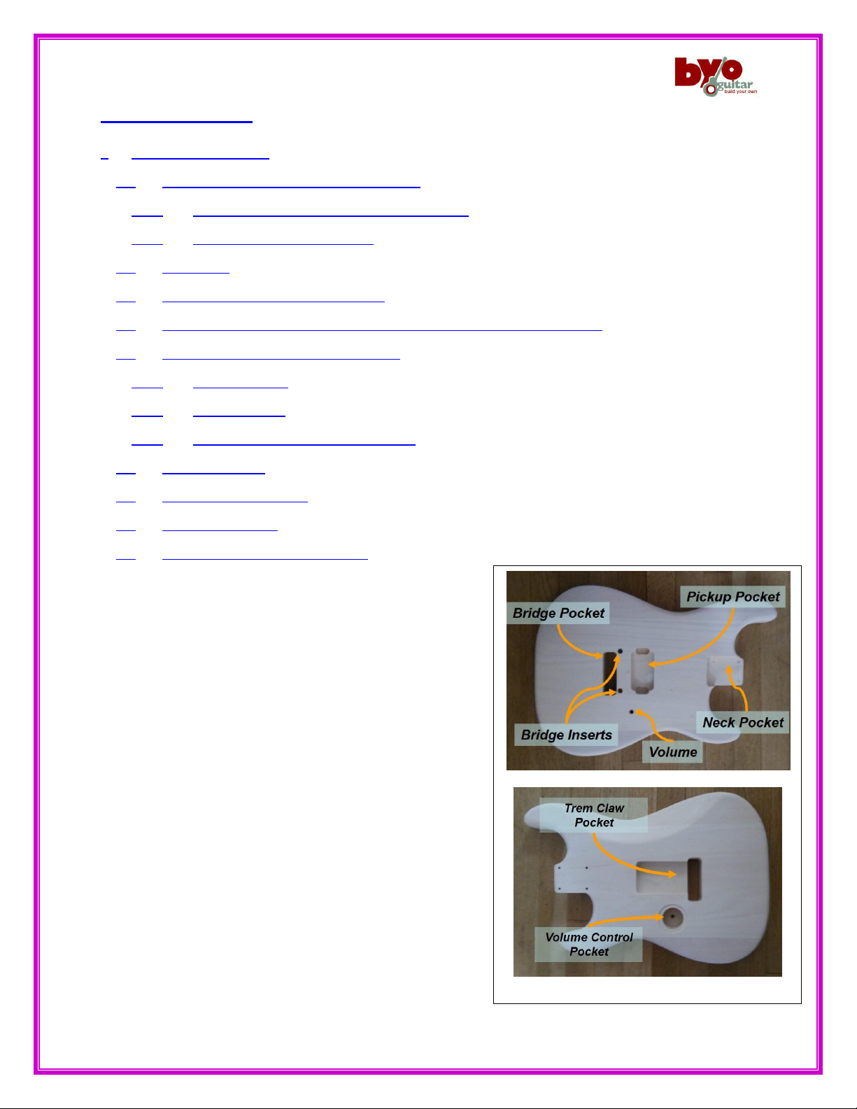
2.2 The Bridge .................................................................................................................................- 2 -
2.3 Fit check & Alignment of the Pickup.........................................................................................- 2 -
2.4 Check Tremolo Claw Alignment and Fit Check (item #5 on material list).................................- 3 -
2.5 Fit check of the back covers (Fig 2.5.1).....................................................................................- 3 -
2.5.1 Tremolo cover:..................................................................................................................- 3 -
2.5.2 Volume Cover:...................................................................................................................- 3 -
2.5.3 Truss Rod Adjustment Access Cover.................................................................................- 3 -
2.6 Check Strap Pins........................................................................................................................- 3 -
2.7 Check Tuner Alignment.............................................................................................................- 4 -
2.8 Check Output Jack.....................................................................................................................- 4 -
2.9 Mockup and Fit Check complete! .............................................................................................- 4 -
3 Finish .................................................................................................................................................- 1 -
3.1 Finish Application Steps ......................................................................................................- 2 -
3.1.1 Solid Color finish: ..........................................................................................................- 2 -
3.1.2 Pigmented Translucent, Gel stain or alcohol dye finish:.......................................- 2 -
3.1.3 Penetrating Stain or water based dye finish: ..........................................................- 2 -
3.2 Explanation of Sequence Steps:..........................................................................................- 2 -
3.2.1 Sanding the Body and Neck.........................................................................................- 2 -
3.2.2 Appling Grain Filler ......................................................................................................- 3 -
3.2.3 Applying Sanding Sealer ..............................................................................................- 3 -
3.2.4 Solid Color Primer.........................................................................................................- 3 -