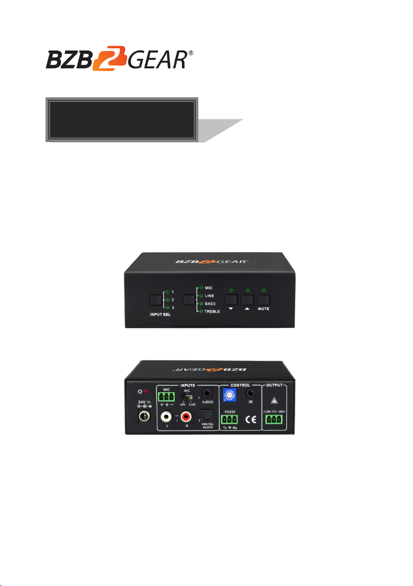
40 Watt Power Amplifier
Table of Contents
1. Product Introduction .................................................................................................... 1
1.1 Features ............................................................................................................. 1
1.2 Package Contents ............................................................................................. 2
2. Panel Description ........................................................................................................ 2
2.1 Front Panel ........................................................................................................ 2
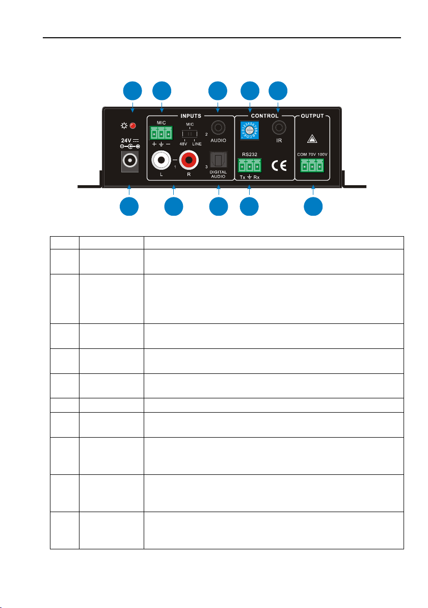
2.2 Rear Panel ......................................................................................................... 3
3. System Connection ..................................................................................................... 4
3.1 Usage Precautions ............................................................................................ 4
3.2 System Diagram ................................................................................................ 4
3.3 Audio Connection ............................................................................................... 4
3.3.1 Audio Output ............................................................................................ 4
3.3.2 Audio Inputs ............................................................................................. 5
3.4 System Applications ........................................................................................... 6
4. System Operation ....................................................................................................... 7
4.1 Operation of Front Panel ................................................................................... 7
4.1.1 Audio switching ........................................................................................ 7
4.1.2 Volume/EQ controlling ............................................................................. 7
4.2 Operation of IR Remote ..................................................................................... 8
4.3 Operation of Control Software ........................................................................... 9
4.3.1 Connection with Computer ...................................................................... 9
4.3.2 RS232 Control Software .......................................................................... 9
4.3.3 Running Environment ............................................................................ 10
4.3.4 Function Settings ................................................................................... 10
4.3.5 RS232 Communication Commands ....................................................... 11
5. Specifications ............................................................................................................ 13
6. Panel Drawing ........................................................................................................... 14
7. Troubleshooting and Maintenance ............................................................................ 15
8. Tech Support ............................................................................................................. 15
9. Warranty ................................................................................................................... 16
10. Mission Statement .................................................................................................. 16