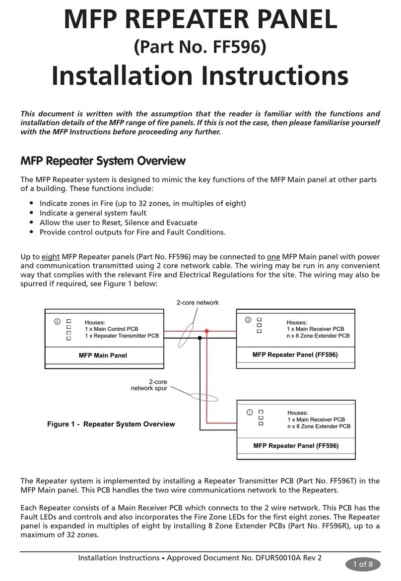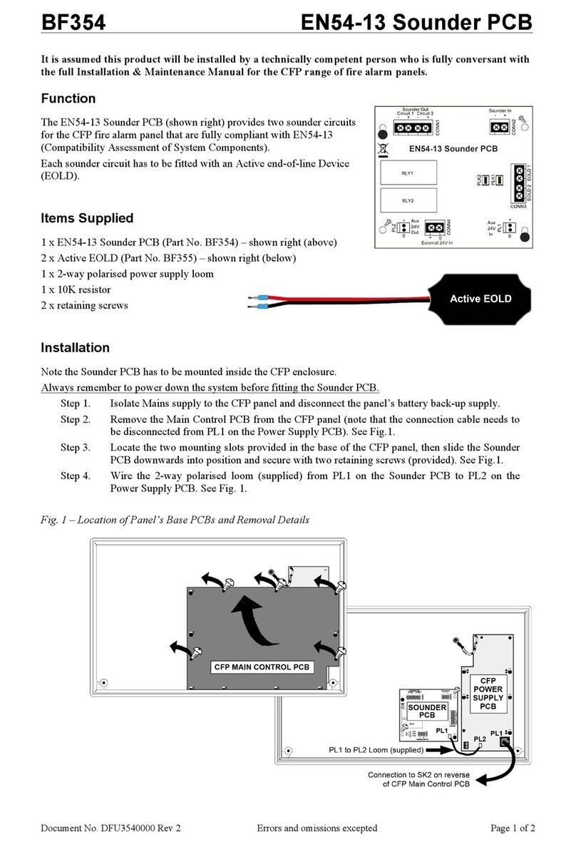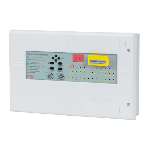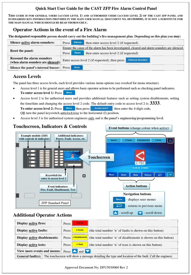
HUSH-ACTIV KITS BS 5839-6 Grade C Domestic Fire Alarm Kits
INSTALLER’S GUIDE
Approved Document No. DFU0005086 Rev 3
The Hush-ActiV standalone domestic fire alarm kits have been designed to reduce the
incidence of false alarms in HMOs, dwellings, flats, etc., by providing a reliable, fully
monitored fire detection and alarm system complete with hush (silence) and test functions.
3
CONTROLLER
230V AC
ActiV
Multisensor
CONVENTIONAL ZONE & SOUNDER CIRCUITS
HUSH-ACTIV CONTROLLER
ActiV
Smoke Detector
ActiV
Heat Detector
ActiV
Base Sounder
S
HPPSU
230V/24V
HA508
33
EOL Resistor
(Sounders)
EOL Capacitor
(Detectors)
2
1 of 3
Approved Document No. DFU0005086 Rev 3
HUSH-ACTIV WIRING AND CONNECTIONS (see Fig.2 for typical connections)
All wiring must be installed in accordance with all applicable national, regional or local
standards. In the UK this is BS 7671 (Wiring Regulations) and BS 5839-6 (Grade C System).
External
230V/24V
PSU
(HPPSU)
+Ve
0v
CONN1
Li-Ion
Battery
-ZONE+
PLK4
DC
24V -SNDR+
ZONE +
ZONE -
SNDR +
CONV ZONE
CIRCUIT
ActiV Multisensor
+ Diode Base
ActiV Heat Detector
+ Diode Base
EOL Capacitor
+Ve
ActiV
Base Sounder
-Ve
EOL Resistor
S
+Ve
CONV SOUNDER
CIRCUIT
-Ve
-Ve +Ve
S
+Ve
ActiV Smoke Detector
+ Diode Base
-Ve
Connect EOLs
in last device
on both sounder
and zone circuits.
Optional 470 ohm
Call Point
(Not supplied)
Additional ActiV
Base Sounder
(Not supplied)
1234
ON SW2 PL2
CON1 (-ZONE+): The conventional zone circuit connects up
to 16 ActiV detectors (3 detectors supplied with each kit).
Use the supplied diode bases (C4408D) with the detectors.
CON1 (-SNDR+): The conventional sounder circuit connects
up to 8 ActiV sounders (1 sounder supplied with each kit).
CON1 (DC 24V): Connects to 24V external PSU. Typically,
1mm to 1.5mm twin & earth cable may be used.
PLK4: Battery connector. To reduce battery drain, it is
recommended that the battery is connected after the
external 24V power is applied.
Fig.1 - Typical HAK/1 Hush-ActiV System
FIRE ALARM
ancillaries
FIRE ALARM
ancillaries
THIS EQUIPMENT MUST BE INSTALLED AND MAINTAINED BY A SUITABLY SKILLED AND
TECHNICALLY COMPETENT PERSON. ENSURE ALL POWER IS REMOVED BEFORE INSTALLATION.
Max. number of ActiV
conventional devices per system:
16 ActiV detectors (multisensor, heat, smoke) plus 8 ActiV sounders.
Note: See list above for devices supplied with Hush-ActiV kits.
Max. length of device circuit: 200m Maximum load: 100mA
Operating voltage: 24Vdc Quiescent current: 5mA
Replaceable battery (2Ah):
Li-Ion rechargeable battery (C-TEC supplied only, up to 10 year life).
For 16 devices, provides >72 hour standby plus 5 minute alarm
(under normal use).
PL2 open collector outputs: Each output max 20mA @ 30V.
LED indicators:
Supply (Green) LED. Lit steady when powered from the external PSU. Lit flashing
when external PSU fails and the unit is only powered from the onboard battery.
Fault (Yellow) LED. Lit flashing when there is a wiring / battery fault, device head out.
Alarm (Red) LED. Lit steady when there is a fire alarm.
Hushed (Amber) LED. Lit steady when the unit is in a hushed (silenced) state.
Onboard beeper: Provides audible feedback when a button is pressed and in a fire / fault condition.
Control buttons: 1 x TEST button & 1 x HUSH button - see ‘Hush-ActiV Operation’ overleaf.
Dimensions (mm): 144 (W) x 84 (H) x 25 (D) Body Material: PVC
Weight: 160g IP Rating (EN 60529): IP40 (indoor use only)
Operating Temp.: -100C to +550CHumidity: Max. 95% RH (non-condensing)
HUSH-ACTIV TECHNICAL SPECIFICATION
Fig.2 - Typical HAK/1 Hush-ActiV Connections
Fit 35mm deep double gang UK back boxes for both the Hush-ActiV Controller (HA508) and
the Hush PSU (HPPSU). The Hush-ActiV system should be tested monthly per BS 5839-2, or
applicable national, regional or local regulations.
2 of 3
Advantages of a BS 5839 Part 6 Grade C system over a Grade D system
• Fault monitoring of the power supply.
• Fault monitoring of the interconnecting wiring.
• Allows residents to silence & test the system at floor level.
• Does not require mandatory replacement of devices every ten years.
Read these instructions before installation and operation
Refer to the individual
instructions supplied with
each ActiV device for
wiring and specifications.
Note: Connect the supplied EOL capacitor and EOL resistor across the terminals of the last
device on each circuit to allow the wiring to be line monitored for open and short circuit faults.
All -Ve terminals on CON1 are common -Ve. Typically, the conv. detector (ZONE) and sounder
(SNDR) circuits may be wired using 3-core cable, e.g. 1mm to 1.5mm triple & earth cable. All
terminals can accept cables up to 1.5mm. Alternatively, separate 2 x 2-core cable may be used.
HAK/1 KIT CONTENTS
1 x Hush-ActiV BS 5839-6 Grade C Controller (Part No. HA508)
1 x 230V/24V PSU (Part No. HPPSU)
1 x ActiV Multisensor Fire Detector (Part No. C4414)
1 x ActiV Optical Smoke Detector (Part No. C4416)
1 x ActiV Heat Detector (Part No. C4403A2)
3 x ActiV Detector Diode Bases (Part No. C4408D)
1 x ActiV Base Sounder (Part No. BF431C/CC/W) c/w white lid (Part
No. BF330CTLIDW) & adaptor plate (Part No. BF431QCP)
1 x 0.47μF 50V EOL capacitor; 1 x 6K8 0.25W EOL resistor
HAK/2 KIT CONTENTS As HAK/1, except 2 x Smoke Detectors, 0 x Multisensor Detector
HAK/3 KIT CONTENTS As HAK/1, except 2 x Multisensor Detectors, 0 x Smoke Detector
DIP Switch SW2 1-4 Settings:
DIP1 ON = Delay fire open collector
for 2 minutes - Default OFF.
DIP2 ON = Test mode triggers fire
open collector output - Default OFF.
DIP3 & DIP4 = For future expansion.
PL2 Notes:
1. The wiring to this connection is NOT monitored.
2. The outputs will NOT function with a mains
fail at the HPPSU and therefore must NOT to
be used for life safety purposes.
3. The sounder trigger input is NOT monitored
and will sound at the same tone as the
domestic fire level 1 (FL1) of the Hush-ActiV
system, i.e. there is no separate domestic fire
level 2 (FL2) indications or sound.
Refer to Application Note 0014.1 for PL2
connection details (available @www.c-tec.com).
PL2: Remote Connection.


