Hochiki ekho User manual

Contents
WirelessDevices:aGeneralDescription.........................................................................................................3
SystemStructure............................................................................................................................................3
TechnicalSpecifications..................................................................................................................................4
UsingExpanders.............................................................................................................................................5
GeneralInstallationGuidelines.......................................................................................................................6
FrequencyChannelsandTraffic......................................................................................................................7
ConnectingtheTranslator..............................................................................................................................7
Addressing......................................................................................................................................................8
ProgrammingandServicinginTranslatorMenu.............................................................................................9
EKHOConfigurator:GettingStarted.............................................................................................................11
ProgrammingDevices...................................................................................................................................12
Configuration................................................................................................................................................13
Servicing.......................................................................................................................................................14
WirelessConnections...................................................................................................................................16
OtherLanguages...........................................................................................................................................18
www.acornfiresecurity.com

TheEKHOwirelessfiresystemcanbecomposedofa
combinationofthefollowingwirelessdevices:
EK‐WL8‐TRHWirelesstranslator:thisdeviceisthe
core of the wireless system; it communicates
continuouslywithwirelessdevices,suchassensors,
callpoints,sounders,etc.Thetranslatorconnectsto
awiredcontrolpanelviaasignalingloop.
Thewholesystemiscontrolledbythecontrolpanel
similartoanyotherfirealarmsystem.Thetranslator
isthegatewaybetweenthecontrolpanelandthe
radiodevices.
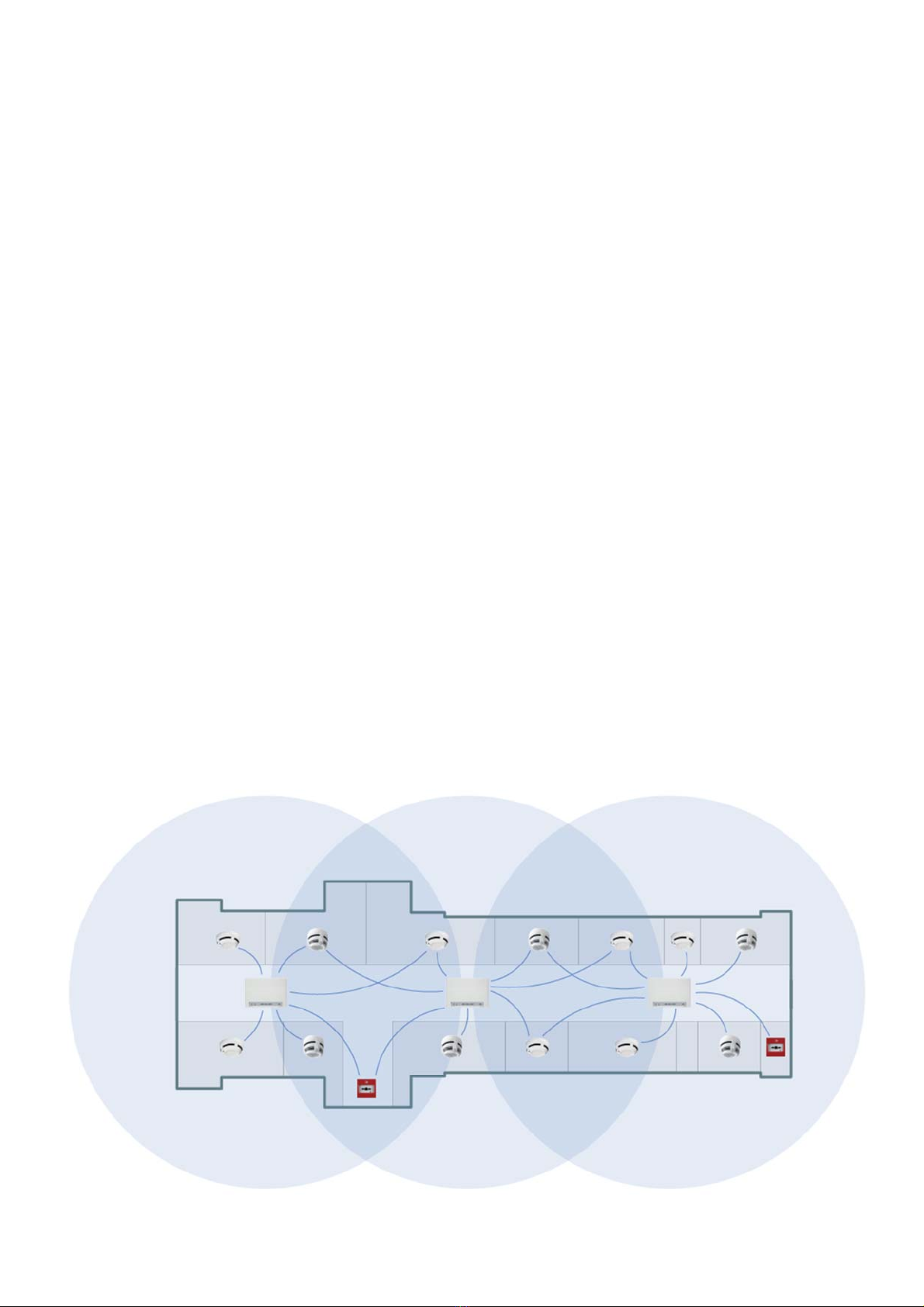
EK‐WL8‐EXP Wireless expanders: The translator
communicates with other wireless devices only if
they are in its communication range. Wireless
expandersareusedwhennetworkcoverageneeds
to be expanded and/or the environment poses
difficulties to radio communication. These devices
actasrepeatingdevicesforcommunicationbetween
wirelessdevicesandthetranslator.
Sensors (EK‐WL8‐O, EK‐WL8‐H, EK‐WL8‐OH, EK‐
WL8‐OV)aredesignedtodetectsmokeand/orheat
intheenvironment.Ifheatand/orsmokeispresent
and exceeds a defined limit, the wireless system
triggersanalarmcondition.
EK‐WL8‐SND Sounders play an audible warning
whenthewirelessfirealarmsystemisactivated.
EK‐WL8‐CPCallpointsprovideamanualmethodfor
initiatingafirealarmcondition.
EK‐WL8‐IN Input modulesreceiveasignalfrom
wired conventional (non‐addressable) sensors and
devicesandtransmitthemtothetranslator
EK‐WL8‐OUT Output modules receive control
commands from the translator to open/close the
connectedcircuit.Designedtocontroltheoperation
/ state of external devices or plant such as air
conditioning/doorrelease/emergencyshutdown.
Thefirealarmpanelcontrolsthealarmsandevents
of the entire system. The EK‐WL8‐TRH wireless
translatorisconnecteddirectlytothefirealarm
panelviatheHochikiESPEnhancedSystemProtocol
andcommunicateswiththewirelessdevicesandthe
wirelessexpanders.
Thefirealarmpanelreceivesallwireless
communicationsthroughthewirelesstranslatorand
transmits back the alarms and events through the
wirelesstranslatortothewirelessdevices.
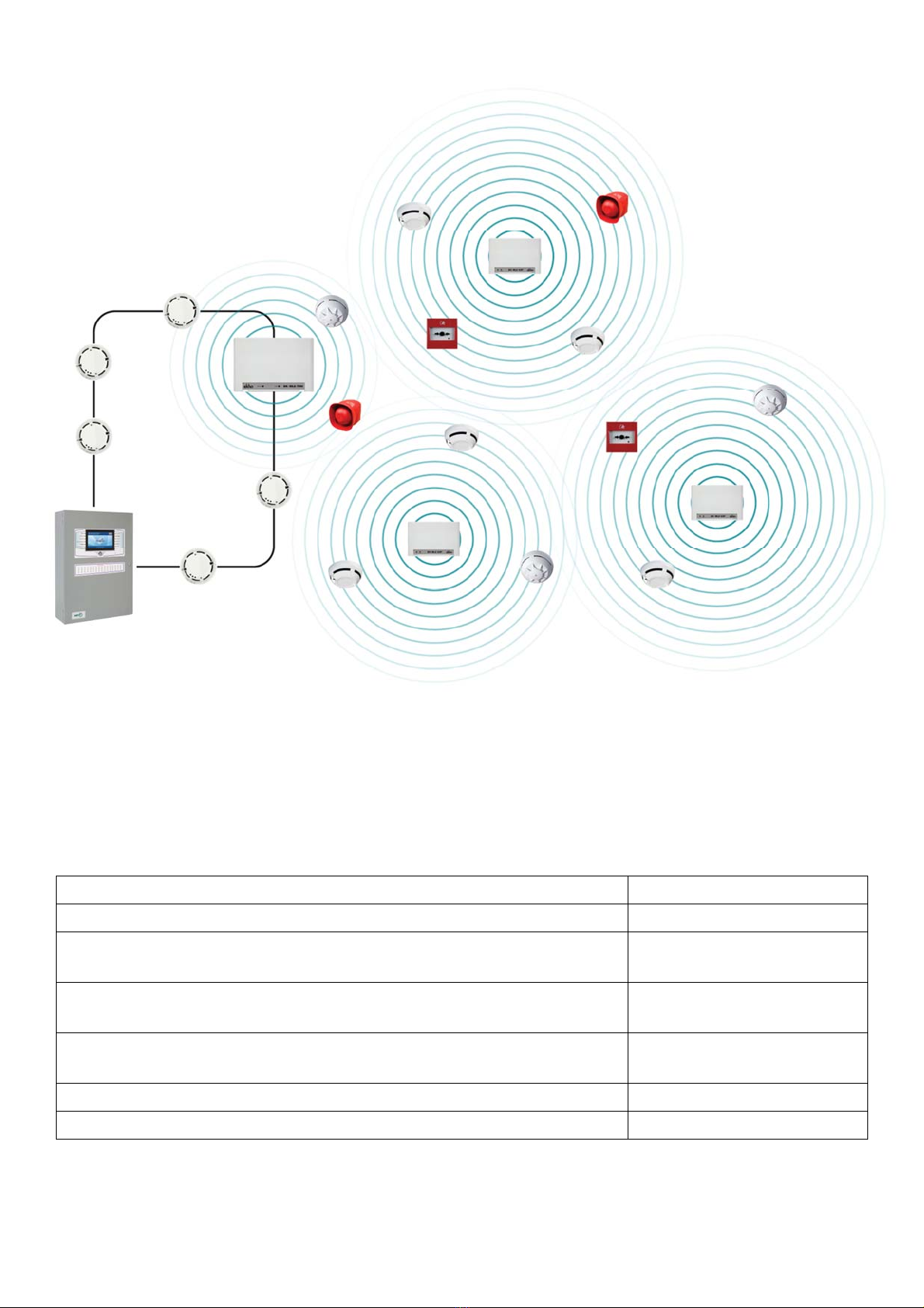
The wireless system is based on a mesh network,
whichoperatesbasedonthefollowingrules:
eachdeviceautomaticallychoosesitsparent
expander;
expandersautomaticallyformanetworkfor
delivering information to the main control
panel.
Wirelessdevicesdonotneedtobeassignedtoa
specificexpandernordotheexpandersneedtobe
specifiedhowtocommunicatewitheachother.The
wireless devices are simply initialized to the
translatorandthenprogrammedtothefirecontrol
panel.
WirelessDevices:aGeneralDescription
SystemStructure
www.acornfiresecurity.com

Maximumnumberofdevicessupportedbyasingletranslator 126
Maximumnumberofexpanderssupportedbythetranslator 126
Communicationrangebetweenatranslatorandanexpanderorbetween
twoexpanders 2000m
Communicationrangebetweenatranslatororexpanderandawireless
device 1200m
Maximumnumberofexpandersconnectedsequentiallyoneafter
another 10
Maximumnumberofexpandersconnectedtoanothersingleexpander 31
Maximumnumberofdevicesconnectedtoasingleexpander 126
TechnicalSpecifications
www.acornfiresecurity.com

Before installing the system the following points
needtobeconsidered.
Thecommunicationrangebetweenthetranslator,
expanders, and all wireless devices is specified in
‘freeair’.Therangewillvaryandgenerallydecrease
wheninstalledwithinbuildingstructures.
Itisrecommendedthatpreliminarysystemdesignis
madeonpaper.Optimumdevicepositioningcanbe
verifiedduringinstallationandadditionalexpanders
canbeaddedifrequired.
The number of translators / expanders required is
determined by the number of wireless devices
connected to the control panel and the
communicationrangebetweenthetranslators/
expandersandwirelessdevices.
EK‐WL8‐EXPexpandersshouldbeusedwhen
some wireless devices are too far from the
translator
the translator’s communication range does not
coverthenecessaryterritory(e.g.thewhole
buildingoroneofthefloors)
connectionwithwirelessdevicesisweakenedby
externalelectromagneticinterference
thebuildinghasthickwalls,metallicstructuresor
other objects that significantly lower the
communication range of the translator and
wirelessdevices
backup and alternative communication routes
needtobeprovidedinthesystem
The system designer needs to evenly disperse
expandersacrossthepremisesinordertoprovidea
stableconnectiontothenetworkineverypartofthe
building.Wirelessdeviceswillautomaticallychoose
theclosestexpanderthatwillprovidethestrongest
connection.
Whendesigningawirelessfirealarmsystem,itis
importanttokeepinmindthatthecommunication
range between different wireless devices
significantlydependsonwallsandobstaclesthatcan
block radio communication. This is why it is
recommended to check the connection strength
between different rooms in the building before
designingandinstallingthesystem.
UsingExpanders
www.acornfiresecurity.com

Expandersautomaticallyformawirelessnetworkfor
delivering information to the translator. For
example,ifanexpandercan’tcommunicatewiththe
translator directly, it will send the signal through
otherexpandersinthesystem.Thismeansthateach
expanderalsoactsasasignalrepeater.Theprimary
communicationpath tothetranslator ischosenby
the expander automatically and will always be the
shortestpossible(10expandersmaximum).
Ifoneoftheexpanderslosesconnection,thesystem
will reconfigure itself and use alternative
communication routes for delivering signals. The
wirelessdevicesthatwerepreviouslyconnectedto
this expander will also reconnect to another. The
moreexpandersareaddedtothesystemthemore
robustthecommunicationnetworkwillbe.
Wirelessdevicesrequirestablecommunicationand
astrongconnectiontothenetwork.Toachievethis
aim the following recommendations should be
followed:
Select the best place for the wireless device to
ensurethestrongestcommunicationsignal.
Connectionstrengthcanbeviewedviathe
translator’sdisplayorthesoftware.
Selectafrequencychannelthatisfreeorrelatively
freeofinterference,andavoid,ifpossible,channels
thatarealreadyallocated.
Avoidinstallingthewirelessdevicescloseto:
equipmentusinglargeamountsofelectrical
current
large metal objects, structures or metal
ceilingstructures
fluorescentlightingfixings
computers, their cabling, and network
cabling.
Translators and expanders should be installed
perfectlyflatonthewallonalevelofatleast2–2.5
metersabovefloorlevel.
Allwirelessdevicesmustoperateinacompatible
environment:environmentalfactorslike
temperature,humidity,andsoon,mustfallinthe
device’sacceptableoperatingranges,asspecifiedin
theirinstallationinstructions.
Communicationrangeinabuilding
Communicationrange
Max.numberofwalls
Walltype Expander–Expander Expander–Device
Wood,drywall 150m 70m 3
Brick,sandwichpanel
Thickness<250mm80m 40m 3
Brick
Thickness>250mm50m 25m 3
Reinforcedconcrete 50m 25m 2
GeneralInstallationGuidelines
www.acornfiresecurity.com

Wirelessdevicescancommunicatevia6different
frequencychannels.
During system commissioning the installer can
assess which channel has the lowest noise and
interferencelevelandprogramthewirelesssystem
to operate on that channel. This will significantly
improvecommunicationbetweendifferentwireless
devices in the system (as opposed to choosing a
random frequency channel that may not have the
idealconditionsforcommunication).
The wireless system can be characterized by the
amountoftrafficinthenetwork.Themoredevices
youhave,thehigherthetrafficwillbe.
It is recommended to keep the traffic value under
10%. One frequency channel can accommodate
around2000devices.
Atranslatorandthewirelessdevicesconnectedtoit,
make up an “independent” wireless system. If the
firecontrolpanelhasseveraltranslatorsconnected
toit,thenitwouldbepossiblethatsomeofthemwill
use the same frequency channel. Every wireless
network is assigned a unique system code, which
preventscommunicationconflictsbetweendifferent
wirelesssystemsintheabovecondition.
Refertoandfollownationalcodesofwiringand
cablingpracticeandotherinternationallyrecognized
standards.
Loopterminalsarepolarity sensitive, so connect
them adequately according to the following
instructions.
It's recommended not to install more than 10 EK‐
WL8‐TRVinasingleloop.
If10translatorsareconnectedtoasingleloop,the
resistanceintheloopshouldnotexceed16Ohm
FrequencyChannelsandTraffic
ConnectingtheTranslator
www.acornfiresecurity.com

Everywirelessdevicehasauniqueaddress(number)
that is automatically assigned during the
configurationofthewirelesssystem.
The wireless protocol uses its own addressing
system, separate from the analogue intelligent
protocol of the main control panel. The translator
willassignandmanagetheaddressingautomatically.
Theaddressofthetranslatormustbespecifiedand
thisdatainserteddirectlyusingthetranslator’sbuilt‐
in display. This address is used only by the main
control panel and is indicated as the ‘starting
address’.Eachwirelessdevicewillalsohaveitsown
address in the main control panel. The numbering
willbeginwiththestartingaddressofthetranslator.
For example, if the starting address is “1”, the
following wireless devices that are added to the
systemwillbegivenaddress“2”,“3”,“4”,“5”andso
on. If another starting address is specified, for
example, “34”, the wireless devices will be
automatically readdressed with “35”, “36”, “37”,
“38”andsoon.Thesearetheaddressesinthe
analogue–intelligentprotocolusedbythecontrol
panel. Wireless protocol addresses remain
unchanged.
Informationaboutthewirelesssystemhastobe
transferredto thecontrolpanel. Thecontrolpanel
has a specific command that allows it to copy the
wireless system configuration to the panel’s
memory. For full instructions, please refer to the
controlpanelusermanual.
Addressing
www.acornfiresecurity.com

ProgrammingandServicinginTranslatorMenu
The"Configuration"menucanbeaccessedbyenteringapassword.Defaultpassword‐"33333".Itcanbe
changedinthe"PSWChange"sub‐menu.
Addingdevices
Toaddanewdeviceinthesystem,usetheADDcommandinthe“Configuration”menu
Changingsettings
Eachdevicehasdifferentsettings,suchasthesensitivityofsmokesensorsoralarmsignaltypeof
sounders.Themajorityofthemcanbeadjustedinthe“Configuration”menu.
www.acornfiresecurity.com

EKHOConfigurator:GettingStarted
Tostartusingthesoftware,connectyourPCtothetranslatorviathe
microUSBport.
Createanewconfigurationfile.Thisfilestoresallinformationonthesystem.
SelectWL8‐TRVandchooseUSBportintherightwindow
Sendthe“Program”commandtothetranslator.
Aftertheprogrammingiscomplete,press“Activateeventprotocoling”sothatthePCmaintainsaconstant
connectionwiththetranslatorandupdatesthestateofthesysteminreal‐time.
www.acornfiresecurity.com

ProgrammingDevices
Usethecontextmenuof
thetranslatortoaddnew
devices.
Press“Initialize”tolink
thedevicewiththe
translator.
Afterpressingthe“Prog”
buttononthedevice,it
willappearinthepop‐up
window.Selectitand
press“Continue”to
confirm.
www.acornfiresecurity.com

Configuration
Eachdevicehasanumberofdifferentpropertiesthatcanbechangedintherightwindow.Hereareafew
examples:
WL8‐TRHsettings
System code is the unique identification number of the
wireless network. Each translator must have a different
code.Itisgeneratedrandomlywhenanewconfiguration
fileiscreated.
Thewirelesssystemcanoperatein6wirelesschannels.If
the building already has some other equipment that
operatesinthe868MHzrange,itmightinterferewiththe
wirelesssystem.Inthiscase,youmayneedtochangethe
“Channelnumber”.
“Childdevicescontrolperiod”isthetimedelaybeforethe
translatorcreatesafaulteventifit’snotreceivingany
signalsfromadevice
WL8‐Osettings
If you choose the “Increased” option in “Initialization
security”, you will need to enter a password in order to
initialize the device. The password can be found on the
labelonthedevice.
“Indication” section includes parameters allowing you to
turnon/offLEDindicationinanormalstate,inthealarm
state,orincaseoflowbattery.
Options in “Control circuits” enable or disable protocol
eventsincaseoflowbatteryortampering.
The analysis channels section allows you to turn off the
smokesensorandsetitssensitivity.
WL8‐OVsettings
Ifthesoundsignalistooloud,select‐12dBintheOutput
powerattenuationparameter.
“Stop alert when removed from the base” is a useful
functionthatcanbeturnedonduringsystemtesting.
WL8‐OVcanactivateafteritdetectssmokeevenifit
doesn’t receive an activation command from the control
panel,thusactinglikeastandalonefiresensor.Thesound
signaltypecanbespecifiedinthe“Alerttypeincaseofself
alarm”parameter.
www.acornfiresecurity.com

Whenyouaredoneconfiguringthesystem,pressthe“Applychanges”buttonatthetopofthewindow.
Thesoftwarewillsavetheconfigurationfileandwriteallofthesettingsintothememoryofthedevices.
Servicing
Eachdevicemakesdifferentmeasurementsthatyoucanseeinreal‐time using the Strelez‐Master
software.Forexample,allwirelessdeviceswillsendvoltagelevelsfortheirmainandbackupbattery,and
smokesensorswillsendthedustlevelinitschamber.Thisinformationcanbeveryusefulforperforming
maintenanceactivities.Toaccessthisdata,gototheServicetab.
Thetablecontainsalloftheavailableinformationforeachdevice
Someofthemoreimportantcolumnsinclude:
Actuality–timesincethelastupdate
Primary/standbysupply–voltagelevelofthemainandthebackupbattery
Fault–currentstateofthedevice
AnalogvalueandAnalogtype–willcontaindifferentvaluesbasedonthetypeofthedevice.Forexample,
smoke sensors measure the smoke (Analog value 1) and dust (Analogvalue3)levelsinthesensor
chamber.
Thenormalvoltagelevelofafullbatteryinawirelesssensoris3.2V.Thedevicewillgenerateafaultevent
ifthevoltageisintherangeof2,75±0,1V.Knowingthisinformation,youcanuseEKHOConfiguratorto
planbatteryreplacementaheadoftime.
Thesameprincipleappliestothedustlevel.Thedevicegoesintoafaultstatewhenthevalueisover127,
however,itisrecommendedtocleanthechamberwhenthedustlevelexceeds64.Byanalyzingtheanalog
valuesyoucanplanmaintenanceproceduresinadvanceandnotriskanypotentialfalsealarms.
www.acornfiresecurity.com

Double‐clickanydevicetoseethehistoryof
measurementsitmade.Theyareloggedwhenthe
translatorisconnectedtoaPCandEKHO
Configuratorisrunning.
EKHOConfiguratorsoftwarehasthe“Problem
filter”featurethatcouldusefulforsystem
maintenance.Openitusingthebuttononthetop
ofthetableandselectthedesiredtimeinterval
(e.g.amonth).
The“Problems”columnwillnowdisplaythe
numberoffaultsandalarmsthatoccurredinthat
timeframeforeachofthedevices.Youcansort
thetablebythiscolumnsothatthedevicesthat
needtobeinspectedandfixedduring
maintenancewillbeattheverytopofthelist.
TheeventprotocolwindowislocatedinthebottompartoftheControltab.Hereyoucanseeallevents
thatoccurinthesystem.Thecolorshowsyouiftheeventiscommon(white),awarning(yellow),oran
alarm(red).
www.acornfiresecurity.com

Abovethelistofeventsyouwillfinddifferentactionsavailabletotheuser:
–downloadfullprotocolfromthetranslator(upto4000events)
‐enable/disableautomaticscrollingwhenneweventsoccur
–clearthewindow
–exportfulllisttoanHTMLfile
‐filternecessaryeventsandexportto.txtor.csv
Youcansorttheeventlistbyoneofthecolumns,
andsetafilterforeachofthecolumns.For
example,youcansettheprotocolwindowtoonly
displayalarmmessagesoreventsfromacertain
device.
WirelessConnections
TheEKHOConfiguratorsoftwareallowsyoutoanalyzethenetworktopologyand connectionstrength
withwirelessdevicesinreal‐time.Todothat,gotothe“Wirelessconnection”tab.
Tobeginanalyzingthenetwork,turnon“Readsignalstrengthdata”
Thetableallowsyoutoseetheconnection
strengthwitheachdeviceinthesystem.The
“Evaluation”columnshowsconnectivitylevels
withthedevicesonascalefrom2to5.Itis
recommendedthatalldeviceshaveaconnection
rateofatleast4or5.The“Actuality”columntells
youhowmuchtimehaspassedsincethe
connectivitylevelshavebeenlastupdated.
www.acornfiresecurity.com

Bydouble‐clickingonadeviceyoucanopena
graphofconnectionstrengthwiththisdeviceover
acertainamountoftime.Connectionstrength
historyisloggedonlywhilethetranslatoris
connectedtoacomputerandEKHOConfiguratoris
running.
Thegraphinthelower‐leftcornershowsthecurrentsignallevelandtrafficpercentageinthenetwork.
Inagoodfunctionalsystem,thebaseleveloftheSignalgraphshouldfallintherangefrom‐110to‐90
dBmandTrafficshouldnotexceed10%
Thenetworktopologywindowshowshowwireless
devicesareinterconnectedwitheachotherinthe
system. The bigger the system is, the more
complicatedthegraphwillget.
Thecolorofthelinealsorepresentstheconnection
strength(green–5,yellow–4,orange–3).
Optionsontherightallowyoutochoosehowthe
graph is displayed in the window, and toggle the
visibilityofbackupcommunicationroutes.
www.acornfiresecurity.com
Table of contents
Other Hochiki Fire Alarm manuals
Popular Fire Alarm manuals by other brands

National Security Systems
National Security Systems All-Safe 4 Zone P.A. SYSTEM instruction manual

Cooper Notification
Cooper Notification ST-C installation instructions

Tecnoalarm
Tecnoalarm Tecnofire TFA2-596 Installation

Teknim
Teknim TFB-1166 Installation & user manual

Faraday
Faraday 15220A owner's manual

Honeywell
Honeywell NOTIFIER ONYX FirstVision Installation and operation manual