5 of 8
Repea er Panel Indica ors and Con rols
Repeater Indi ators
The Main Receiver PCB, mounted in the MFP Repeater panel, has four system status EDs and eight Fire
Zone EDs, which are detailed below.
The General Fire ED (red) flashes when there is an unsilenced fire state on the system. When there is a
silenced fire state on the system, this ED is lit steady. The ED is also momentarily lit during a Reset /
amp Test cycle.
The General Fault ED (yellow) flashes when there is any fault on the system and is momentarily lit during
a Reset / amp Test cycle.
The ocal Fault ED (amber) indicates when there is a fault generated at the Repeater panel. This ED will
light intermittently under the following conditions:
• Power is supplied to the Repeater but there are no communications with the MFP Main panel
• There is a fault associated with the local Auxiliary Power supply
• The microprocessor on the Repeater has failed
• The ocal Fault ED will also light momentarily during a Reset / amp Test cycle.
The Supply Healthy ED (green) indicates that the Repeater is receiving power.
If there is a fault with the local Auxiliary Power supply then the Supply Healthy ED will flash. This ED
will also go out momentarily during a Reset / amp Test cycle.
The Fire Zone EDs (red) flash when there is a new fire on a particular zone.
If the system is in a silenced fire state, then the Fire Zone ED for a zone previously triggered will be lit
steady. The Fire Zone EDs are momentarily lit in sequence during a Reset / amp Test cycle.
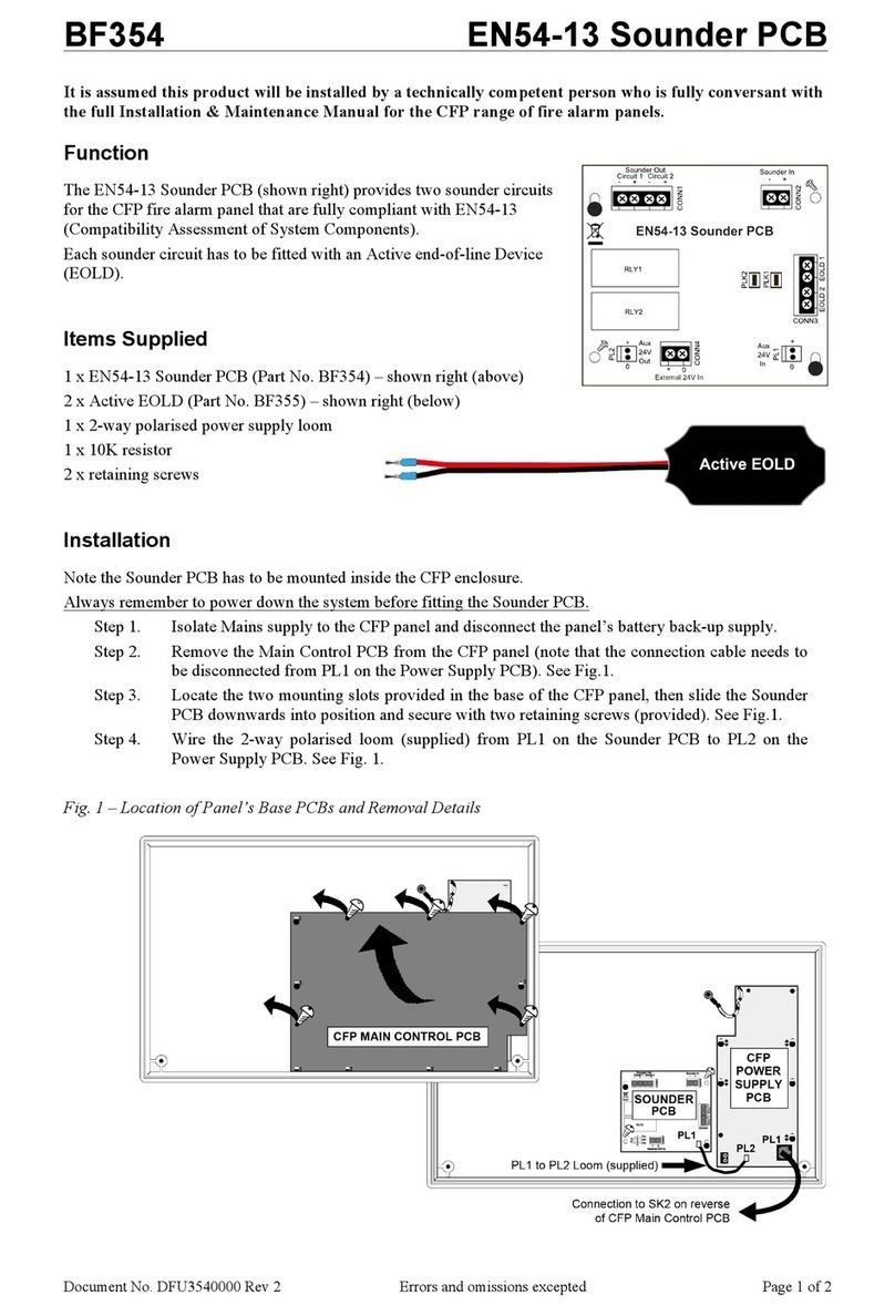
The Repeater panel may be extended in multiples of eight zones, up to a maximum of 32 zones, by the
addition of an Extender kit (Part No. FF596R). This kit consists of an 8 Zone Extender PCB, looms and
mounting hardware (see 'Repeater Panel Installation' section, page 6).
The panel’s beeper will sound when there is any fault condition on the system, and depending on the
type of fault condition the beeper may be muted by pressing the Silence button when the keyswitch is
in the Arm Controls position.
Repeater External Controls
The panel’s keyswitch enables its buttons to be used when it is in the Arm Controls position. In this
position the key cannot be removed.
The Reset button, when pressed, initiates a System Reset or amp / Beeper Test cycle, unless the system
is in an unsilenced fire state, in which case it is inactive.
The Silence button, when pressed, mutes the fault beeper (in the case of a new system fault), or silences
the alarm sounders, moving the system to an silenced fire state.
The Evacuate button, when pressed, activates the Alarm sounders, moving the system to an unsilenced
fire state. To deactivate the sounders the Silence button must be pressed. If the system is set up for
delayed sounders then pressing the Evacuate button during a delay period will activate the alarm
sounders immediately, even if the keyswitch is not in the Arm Controls position.
Repeater Internal Controls
Aux PSU Sense P K1 must be linked to disable PSU sense. If an Auxiliary Power Supply is used locally then
this link must be removed. If the link is removed and the Auxiliary Power Supply fails, or is not fitted,
then the Repeater will sense a fault condition and indicate appropriately. Address ink SW4 sets the
address of the Repeater.
FF596 MFP Repeater Panel
Installation Instructions •Approved Document No. DFUR50010A Rev 2


