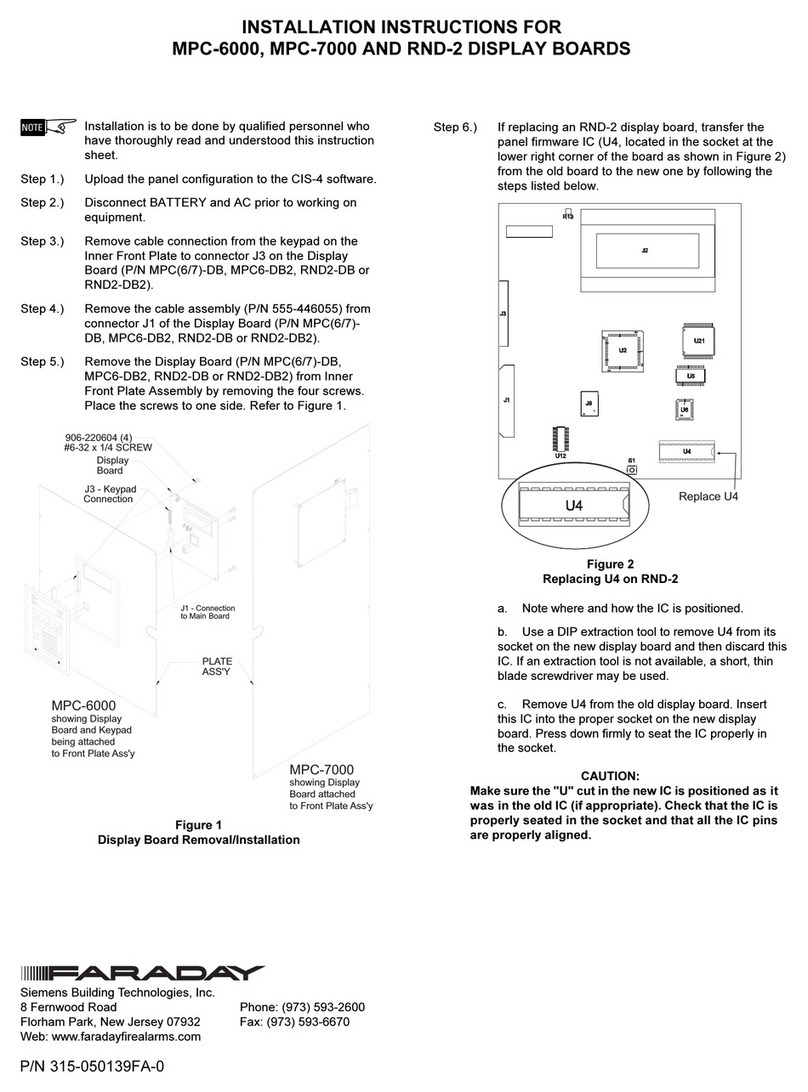
Faraday 15220A User manual

FARADAY
15220A / 15240A
15220A-240/15240A-240
FIRE ALARM
SYSTEM CONTROL UNIT
OWNERS MANUAL
P/N 445926
ISSUE I Rev. C
10/98
805 S. Maumee St. /Tecumseh, MI 49286
Phone:(517)423-2111/ Fax:(517) 423-2320
Copyright © 1998, Faraday, LLC All Rights Reserved
FARADAY
firealarmresources.com

TABLE OF CONTENTS
PAGE
INSTALLATIONANDWARRANTYINFORMATION i
PREFACE ii
PANELPERFORMANCEPARAMETERS iii
SECTIONI DESCRIPTIONS
15220A/15240AFIREALARMSYSTEMCONTROLUNIT I-1
15216SEMI-FLUSHTRIM I-1
140476 A.H.BATTERYSET I-1
1404810A.H.BATTERYSET I-1
1404915A.H.BATTERYSET I-1
14050BATTERYCABINET I-1
15212REMOTEANNUNCIATORMODULE I-1
15213AMARCHTIME/TEMPORALSIGNALINGMODULE I-1
15219ZONERELAYMODULE I-1
15209CITYTIEMODULE I-2
15215CITYTIE/AUXILIARYRELAYMODULE I-2
15217AUXILIARYRELAYMODULE I-2
15206D.A.C.TINTERFACEMODULE I-2
15220A/15240ASPECIFICATIONS I-3
SECTIONII OWNERSINSTRUCTIONS
ALARMOPERATION
ALARMINDICATIONS II-1
TROUBLESILENCING II-1
SIGNALSILENCING II-1
SYSTEMRESET II-1
TROUBLEOPERATION
TROUBLEINDICATIONS II-2
TROUBLESILENCING II-2
SPRINKLERSUPERVISORYOPERATION
SUPERVISORYINDICATIONS II-2
TROUBLESILENCING II-2
SWITCHANDL.E.D.FUNCTIONS II-3
SYSTEMTESTINGANDMAINTENANCE II-4
15220A/15240AOPERATINGINSTRUCTIONS II-5
SECTIONIII INSTALLATIONINSTRUCTIONS
(FORQUAILIFIEDPERSONNELONLY)
15220A/15240ACONTROLUNITINSTALLATION III-1
15220AWIRINGDIAGRAM III-8
15240AWIRINGDIAGRAM III-9
WIRINGDIAGRAMFORHEATDETECTORS&PULLSTATIONS III-10
WIRINGDIAGRAMFORSUPERVISORYSWITCHES III-11
WIRINGDIAGRAMFORWATERFLOWSWITCHES III-12
COMPATIBLE2-WIRESMOKEDETECTORS III-13
WIRINGDIAGRAMFORSYSTEMSENSOR2-WIREDETECTORS III-17
WIRINGDIAGRAMFORSYSTEMSENSOR2-WIREDUCTDETECTORS III-18
COMPATIBLE4-WIRESMOKEDETECTORS III-19
firealarmresources.com

SECTIONIIIINSTALLATIONINSTRUCTIONS - (CONTINUED)
(FORQUAILFIEDPERSONNELONLY) PAGE
WIRINGDIAGRAMFORSYSTEMSENSOR4-WIREDETECTORS III-21
WIRINGDIAGRAMFORSYSTEMSENSOR4-WIREDUCTDETECTORS III-22
WIRINGDIAGRAMFORSYSTEMSENSOR4-WIREBEAMDETECTORS III-23
COMPATIBLESIGNALS III-24
WIRINGDIAGRAMFORSIGNALCIRCUIT III-30
WIRESELECTIONGUIDES III-31
BATTERYSIZECALCULATIONS III-32
15212REMOTEANNUNCIATORMODULE III-33
15213AMARCHTIME/TEMPORALSIGNALINGMODULE III-35
15219ZONERELAYMODULE III-37
15209CITY TIEMODULE III-39
15215CITYTIE/AUXILIARY RELAYMODULE III-41
15217AUXILIARYRELAYMODULE III-43
15207SUPERVISORYMODULE III-45
15206D.A.C.T.INTERFACEMODULE III-46
McCULLOHTRANSMITTERCONNECTIONS III-48
SECTIONIV TROUBLESHOOTINGGUIDE
(FORQUAILIFIEDPERSONNELONLY)
15208TROUBLESHOOTINGMODULE IV-1
MAINBOARDTROUBLES IV-2
OPTIONMODULETROUBLES IV-2
firealarmresources.com

IMPORTANT INSTALLATION AND WARRANTY INFORMATION
WARRANTYINFORMATION: TheManufacturerprovidesalimitedwarrantyforoneyearfromthedateofpurchasetothe
Original Purchaser of this product. The Original Purchaser is the party to whom the Manufacturer issued its Sales Order,
generallytheManufacturer'sdistribution. inordertopreservethiswarranty,itisimportantthattheproductbeservicedonly
bypersonswhohavebeenproperlytrainedandauthorizedbytheManufacturer.
Other parties involved in the installation of this product may have also provided a warranty which may be different than
that of the manufacturer. The Manufacturer will only be responsible to the Original Purchaser and only for the
Manufacturer's own warranty. For further information regarding the Manufacturer's warranty, contact the Original
Purchaser.
OWNER'S MANUAL: The owner's manual does not purport to cover all the details or variations in the equipment
described, nor does it provide for every possible contingency to be met in connection with installation, operation and
maintenance. All specifications subject to change without notice. Should further information be desired or should
particular problems arise which are not covered sufficiently, the matter should be referred to the Installer or Original
Purchaser listed below.
INSTALLER INFORMATION
COMPANY:_________________________________INSTALLER:___________________________PHONE:______________
ADDRESS:__________________________________CITY:__________________STATE:___________ZIP:____________
DATE INSTALLED:____________________________INSTALLER'S SIGNATURE:___________________________
ORIGINAL PURCHASER INFORMATION
COMPANY:_________________________________________________________PHONE:____________________
ADDRESS:__________________________________CITY:__________________STATE:___________ZIP:____________
PURCHASER'S PURCHASE ORDER NO.:___________________________________________________________
DATEPURCHASED:_____________________________________________________________________________
FARADAY SALES ORDER ACKNOWLEDGMENT NO.:_________________________________________________
ORIGINALPURCHASER'S SIGNATURE:____________________________________________________________
NOTE: A COPY OF THE ABOVE COMPLETED INFORMATION MAY BE REQUIRED BY THE MANUFACTURER
FOR AUTHORIZATION OF WARRANTY SERVICES.
i
firealarmresources.com

National Electrical Code 1993National Electrical Code 1993
National Electrical Code 1993
National Fire Alarm CodeNational Fire Alarm Code
National Fire Alarm Code
Life Safety CodeLife Safety Code
Life Safety Code
NFPA 70-1993
NFPA 72-1993
NFPA 101-1993
OTHERSTANDARDS- Contact the authority having jurisdictionContact the authority having jurisdiction
Contact the authority having jurisdictionContact the authority having jurisdiction
Contact the authority having jurisdiction
for other standards that may apply.for other standards that may apply.
for other standards that may apply.
PREFACE
Alongwith theuseofthisInstruction Manual,theappropriatefollowingstandardsandthe manufacturers'instructionsfor
initiating and signaling devices should be used to install and maintain a functioning Fire Alarm Signaling System.
FORPUBLICATIONSCONTACT:
NationalFireProtection Association
BatterymarchPark
Quincy, MA 02269
ii
firealarmresources.com

iii
PANEL PERFORMANCE PARAMETERS
This control panel will not show an alarm condition without compatible initiating devices (smoke detectors,
etc.)andindicatingdevices(horn,lights,etc.)connectedtoit. Electricalratingsoftheinitiatingandindicating
appliancesmustbeU.L.listedcompatiblewiththeelectricalratingsofthecontrolpanelandmustbeproperly
interconnected. The wiring used for interconnection must be large enough to carry the total current by all
appliances without excessive voltage drop.
This panel must be connected to a dedicated primary electrical source of 120VAC 60Hz that has a high
degreeofreliabilityandadequatecapacityforthispanel. Theonlymeansofdisconnectingthispowersource
shall be available only to authorized personnel and clearly marked “Fire Alarm Circuit Control”.
Thispanelmustalso have connected to it,abatteryset (24V) that has enoughcapacitytoproperly operate
thesystemfor24hoursstandbyand5minutesalarmperNFPA72or60hoursstandbyand5minutesalarm
perNFPA72.Thesebatteriesdolosecapacitywithage. Batteriesmustbereplacedwhentheyfailtoprovide
the panel with the required standby and alarm power or 4 years whichever happens first. These batteries
must be checked for performance at least 2 times per year or more often if local requirements dictate it.
A regular test program should be followed and documented to make sure that each part of the system is
tested as per NFPA 72 or more often if dictated by local code requirements. Malfunctioned units must be
replaced or repaired immediately by factory authorized service personnel.
Note: This panel is designed to show an alarm condition when the initiating devices connected to it detect
specific conditions. These conditions may or may not represent a life threatening condition (ie burnt toast
maynotbealifethreateningconditionbutmaycauseaninitiatingdevicetoindicateanalarmcondition). Also,
evacuationofabuildingorareaunnecessarilymaysubjectindividualstoanunnecessaryhazard. Therefore,
it is most important that building owner, manager or representative promulgate, distribute and/or post
instructions describing steps to be taken when the fire alarm panel signals an alarm condition. These
instructionsshouldbedevelopedincooperationandconformancewithrepresentativesofthelocalauthority
havingjurisdiction.
Asabackuporprecautionarymeasure,itisstronglysuggestedthatoneofthesestepsshouldbeto
notify the local fire department even where the city tie option (or similar device) is included in the
system.
firealarmresources.com

I - 1
The 15220A, Two Zone, and 15240A, Four Zone, Fire Alarm System Control Unit provides manual, automatic,
and waterflow alarm and supervisory service. Zone #1 may be used as a manual, automatic, or waterflow initiating
circuit or it can be programmed to be used with normally open sprinkler supervisory switches. Zone #2 may be used
as a manual, automatic, or waterflow initiating circuit and can also be programmed to be non-silencable for use with
waterflow switches, if required. The control unit has one signal circuit capable of operating up to a total of 2.5A. of
U.L.listedcompatible signals. Thecontrolunit alsoprovidesup to0.3A.of resetable 19-28VDCpowerfor U.L. listed
compatible4-wiresmokedetectors. Theintegralbatterychargeriscapableofcharginguptoa15A.H.,24VDCbattery
setandissupervisedfora disconnected,shorted,orlow(below23VDC)batteryset. Other standardfeaturesinclude
grounddetection,signalsilencing,subsequentalarmsignaling,automaticshortcircuitdisconnectonthesignalcircuit
and trouble buzzer ring back.
The15216Semi-flushTrimisanoptionalfeatureforthe15220Aor15240A FireAlarmSystemControlUnitor14050
Battery Cabinet. The trim allows the cabinet to be mounted up to 3.5" deep into the wall.
ONE OF THE FOLLOWING BATTERY SETS SHOULD BE USED TO SATISFY THE N.F.P.A. REQUIREMENT
OF A SECONDARY AND TROUBLE SIGNAL POWER SUPPLY. SEE SECTION III FOR CALCULATING
BATTERY REQUIREMENTS:
The 14047 Battery Set provides 6 Amp.- Hours of capacity @ 24 volts and mounts in the 15220A or 15240A Fire
Alarm System Control Unit cabinet.
The 14048 Battery Set provides 10 Amp.- Hours of capacity @ 24 volts and mounts in the 15220A or 15240A Fire
Alarm System Control Unit cabinet.
The 14049 Battery Set provides 15 Amp. - Hours of capacity @ 24 volts and mounts in the 14050 Battery Cabinet.
The 14050 Battery Cabinet is used for mounting the 14049 Battery Set. The battery cabinet matches the 15220A
or 15240A Fire Alarm System Control Unit in size, finish, and construction.
The15212RemoteAnnunciatorModuleisanoptionalmoduleforthe15220Aor15240AFireAlarmSystemControl
Unit. Thismoduleprovidesasupervisedannunciatoroutputperzonecapableofdriving 21-28VDCL.E.D.indicators,
a form "C" system trouble contact, and a form "C" general alarm contact. This module also contains a trouble L.E.D.
that will indicate an open condition or activated annunciator output. The form "C" trouble contact is 21-28VDC
powered for driving a 21-28VDC remote trouble unit or it may be programmed dry for other applications.
The 15213A March Time / Temporal Signaling Module isanoptionalmodule for the15220Aor 15240A FireAlarm
System Control Unit. This module provides programming capabilities for the control unit's signal circuit (Note: This
module doesn't provide two additional signal circuits). Circuit #1 can be programmed for steady, march time or
temporal (code 3) signaling. Circuit #2 is non-silencable, intended for steady operation of strobes or other signals
required to be non-silencable.
The 15219 Zone Relay Module is an optional module for the 15220A or 15240A Fire Alarm System Control Unit.
Thismoduleprovidesaform"A"zonealarmcontactperzone,aform"A"generalalarmcontact,andaform"B"general
alarm contact.
The 15209 City Tie Module is an optional module for the 15220A or 15240A Fire Alarm System Control Unit. This
module provides an alarm / trouble transmitter and a form "C" system trouble contact. The module also contains
a city tie disconnect switch and a trouble / off-normal switch L.E.D. The disconnect switch may be activated during
testingorservicingofthesystemtopreventanalarmtransmissionfromthismodule(atroubleoutputwillbegenerated
upon activation of the disconnect switch).
The 15215 City Tie / Auxiliary Relay Module is an optional module for the 15220A or 15240A Fire Alarm System
ControlUnit. Thismodule providesasupervisory / troubletransmitter,an alarm/trouble transmitterora local energy
cityboxtripcircuit,aform"C"systemtroublecontact,andaform"C"generalalarmcontact. Themodulealsocontains
a city tie / relay disconnect switch and a trouble / off-normal switch L.E.D. The disconnect switch may be activated
duringtestingorservicingofthesystemtopreventasupervisoryoranalarm outputfromthismodule(atroubleoutput
will be generated upon activation of the disconnect switch).
firealarmresources.com

I - 2
The 15217 Auxiliary Relay Module isan optionalmodule forthe 15220Aor 15240AFire AlarmSystemControlUnit.
This module provides a form "C" trouble contact and a form "C" general alarm contact. The module also contains
a disconnect switch and a trouble / off-normal switch L.E.D. The disconnect switch may be activated during testing
or servicing of the system to prevent transferring the general alarm contact (a trouble output will be generated upon
activation of the disconnect switch).
The 15206 D.A.C.T. Interface Module The 15206 D.A.C.T. Interface Module is an optional module for the 15220A
or15240AFire AlarmSystemControlUnit. Themoduleprovidesaform"C"troublecontact,aform"C"alarmcontact,
aform"C"supervisorycontact,aform"C"powerfailurecontactanda24VDCpoweroutput.Themodulealsocontains
adisconnectswitchandaoff-normalswitchL.E.D.Thedisconnectswitchmaybeactivatedduringtestingorservicing
of the system to prevent transferring the alarm, supervisory and power failure contacts (a trouble output will be
generated upon activation of the disconnect switch).
firealarmresources.com

I - 3
15220A/15240A GENERAL SPECIFICATIONS
Normal Operating Ambient Temperature: 68°- 77°F (20°-25°C)
Extreme Ambient Temperature: 32°-120°F (0°-49°C)
up to 3 hours
Extreme Relative Humidity: 85% @ 86°F (30°C)
up to 24 hours
Primary Input Voltage:
15220A / 15240A 120VAC 50/60Hz Nominal
(102-132 VAC)
15220A-240 / 15240A-240 240VAC 50/60Hz Nominal
(204-264 VAC)
Maximum Primary Input Current: 2A.
Secondary and Trouble Power Supply: 24 Volt Battery Set
Maximum Charge Voltage: 27.8VDC
Maximum Charge Current: 1.6A.
Battery Capacity: 6-15 A.H.
Maximum Battery Input Current: 3.2A
Resettable Smoke Detector Power
Power Limited
Voltage Range: 24VDC Nominal
Current Output: Up to 0.3A (limited by
battery capacity)
Maximum Ripple: 1.2V
Initiating Circuits:
Power Limited
Style "B" (class "B")
Standby Voltage Range: 16-28VDC
Maximum Standby Current: 7.6 Ma.
Maximum Standby Detector Current: 3.0 Ma.
Maximum Alarm Current: 36 Ma.
Maximum Ripple: 1.2V
Maximum Wire Loop Resistance: 100 ohms
E.O.L. 3.9K Ohm 1/2 W. Resistor
Signal Circuits:
Power Limited
Style "Y" (Class "B")
Alarm Voltage Range: 24VDC Full Wave (nominal)
Maximum Alarm Current: 2.5A @ 24VDC
Maximum Alarm Ripple: 16V
Maximum Standby Current: 0.47 Ma. per circuit
Maximum Wire Loop Voltage Drop: 1.0VDC
E.O.L. Two 47K Ohm 1/2 W Resistors
LISTED TO UL 864 SEVENTH EDITION FILE #S-405
firealarmresources.com

firealarmresources.com

II - 1
OWNERS INSTRUCTIONS
ALARM OPERATION OF THE FIRE ALARM SYSTEM CONTROL UNIT
An alarm is indicated by the following conditions:
A red zone ALARM L.E.D. lights.
The yellow SYSTEM TROUBLE L.E.D. lights in a pulsating manner.
The trouble buzzer sounds in a pulsating manner.
The building alarm signals activate.
If a remote annunciator or trouble unit is used, the alarm and/or trouble is also indicated
at the remote location.
If a remote station type of city connection is used, an alarm signal is sent to the
remote station.
If a local energy type of city connection is used, an alarm signal is sent to the fire
department.
Optional alarm relays may also activate to serve various supplementary functions.
Optional trouble relays will also activate to serve various supplementary functions.
TO SILENCE THE TROUBLE BUZZER:
Push down the TROUBLE SILENCE switch to the silenced position.
TO SILENCE THE BUILDING ALARM SIGNALS:
Momentarily push down the SIGNAL SILENCE switch.
The SIGNAL SILENCED L.E.D. will light, indicating the building alarm signals are off.
An alarm condition in additional zones will re-activate the building alarm signals
and the SIGNAL SILENCED L.E.D. will go out. The building alarm signals may again
be silenced by repeating the procedure above.
NOTE: 1.) If zone #2 has been programmed for use with waterflow switches for
non-silencable signals, once zone #2 is alarmed the building alarm
signals cannot be silenced.
2.) If the 15213A March Time/Temporal Signaling Module is used,
the signals on Signal Circuit #2 are not silencable.
TO RESET AFTER AN ALARM:
First, the device which caused the alarm must be reset.
Manual Pull Staion
Reset the manual pull station using the instructions provided with the station.
Heat Detector
For restorable type detectors, the affected area must be restored to a lower
temperature.
For non-restorable type detectors, the heat detector or the heat detector element
must be replaced.
Smoke Detector
The affected area must be cleared of smoke and the detector should be cleaned.
Waterflow Switches
The activated sprinkler head must be replaced or restored and the sprinkler system
must be restored to its normal condition.
Push down the SYSTEM RESET switch for a minimum of six seconds.
If the trouble buzzer had been silenced, the trouble buzzer will sound again until the
TROUBLE SILENCE switch is returned to the normal position.
If a local energy type of city connection is used, the master box must be reset to clear
the trouble condition.
If a trouble condition still exists, notify the proper personnel for servicing the system
immediately.
firealarmresources.com

II - 2
OWNERS INSTRUCTIONS (Cont'd)
TROUBLE OPERATION OF THE FIRE ALARM SYSTEM CONTROL UNIT
A trouble is indicated by the following conditions:
The yellow SYSTEM TROUBLE L.E.D. lights in a pulsating manner.
The trouble buzzer sounds in a pulsating manner.
Depending on the type of trouble, a yellow zone TROUBLE L.E.D. or a yellow trouble
L.E.D. of an optional module may be lit.
If a remote station type of city connection is used, a trouble signal is sent to the remote
station(s).
If a remote trouble unit is used, the trouble is indicated at the remote location.
Optional trouble relays will also activate to serve various supplementary functions.
TO SILENCE THE TROUBLE BUZZER:
Push down the TROUBLE SILENCE switch to the silenced position.
Notify the proper personnel for servicing the system immediately.
Refer to SECTION IV - TROUBLESHOOTING GUIDE.
Upon repairing the trouble condition, if the trouble buzzer had been silenced, the trouble
buzzer will sound again until the TROUBLE SILENCE switch is returned to the normal
position.
SPRINKLER SUPERVISORY OPERATION OF THE FIRE ALARM SYSTEMS CONTROL UNIT.
(This applies only to control units that have been programmed for sprinkler supervisory switches).
A SUPERVISORY CONDITION IS INDICATED BY THE FOLLOWING CONDITIONS:
The Red Zone #1, Alarm L.E.D. lights.
The Yellow System Trouble L.E.D. flashes.
The trouble buzzer sounds.
If a remote annunciator or trouble unit is used,the alarm and/or trouble is also indicated at
the remote location.
If a supervisory remote station connection is used, a supervisory signal is sent to the remote
staion.
If an alarm remote station connection is used, a trouble signal is sent to the remote station.
If a zone relay module is used, the Zone #1, contact will transfer.
Optional trouble relays will also activate to serve various supplementary functions.
TO SILENCE THE TROUBLE BUZZER:
Push down the TROUBLE SILENCE SWITCH to the silenced position.
Locate the activated switch and return it to its normal position.
If the trouble buzzer has been silenced, the trouble buzzer will sound again until the
TROUBLE SILENCE SWITCH is returned to the normal position.
If a supervisory condition still exists, notify the proper personnel for servicing the system
immediately.
firealarmresources.com

II - 3
SWITCH FUNCTIONS
System Reset: Resets the Fire Alarm Control
Unit and Smoke Detectors
following an alarm condition.
Signal Silence: Operation of the switch during
an alarm condition will silence
the appropriate building alarm
signals.
Trouble Silence: Operation of the switch during
a trouble condition will silence
the control unit trouble buzzer.
After the trouble condition is
cleared the buzzer sounds again
indicating the switch must be
returned to the normal condition.
L.E.D. FUNCTIONS
System Power: (Green) Indicates the primary
(A.C.) power is connected to the
control unit.
Signal Silenced: (Yellow) Indicates the building
alarm signals have been silenced.
System Trouble: (Yellow) Indicates, in a pulsating
manner, that a trouble condition
exists in the fire alarm system.
Zone Alarm: (Red) Indicates an alarm condition
in the associated zone.
Zone Trouble: (Yellow) Indicates an open condi
tion in the associated zone.
NOTE: Zones #3 and #4 are not used on the
15220A Fire Alarm System Control Unit.
firealarmresources.com

II - 4
SYSTEM TESTING AND MAINTENANCE
SYSTEM TESTING
NOTE: Before any tests are conducted, the local Fire Department should be
notified.
1.) System testing and/or fire drills must be performed at the intervals
required by local fire authorities.
Where no local regulations exist, testing schedules for fire alarm systems
are specified in NFPA Standard.
2.) All system tests should be documented. A complete log of device testing
including the type of device, its location, the date of the test and the
operation should be maintained for the system.
3.) Devices should be tested in accordance with manufacturers' instructions.
4.) When testing has been completed all switches must be returned to their
normal position.
DO NOT LEAVE SWITCHES IN THE DISCONNECTED POSITION!
MAINTENANCE
1.) The 15220A or 15240A Fire Alarm System Control Unit does not
require periodic maintenance except that the unit should be kept clean
and dry.
2.) Sealed Lead Acid batteries should be replaced every four years or if the
voltage is low. The terminals should be checked for corrosion and
cleaned, if necessary. To check for low battery voltage, with the primary
power supply disconnected, operate the Fire Alarm System in alarm
(under full load) for five minutes. If the battery voltage is less than 24.0
volts, with the control unit in alarm, replace the battery set.
3.) Maintenance of other devices connected to the control unit should be
done in accordance with the manufacturers' instructions.
RECOMMENDED SPARE CONTROL UNIT PARTS
943504 Fuse 1/2A. 5 x 20mm
943505 Fuse 4a. 5 x 20mm
firealarmresources.com

II - 5
15220A / 15240A OPERATING INSTRUCTIONS
ALARM OPERATION OF THE FIRE ALARM SYSTEM CONTROL UNIT
AN ALARM IS INDICATED BY:
AREDzone ALARM L.E.D. lights.
The YELLOW SYSTEM TROUBLE L.E.D. flashes.
Thetroublebuzzersounds.
Notify the proper personnel to institute preplanned Fire
Alarm Procedures:____________________________________________
Telephone the Fire Department. (Phone No.:___________________),
to advise of the alarm and/or verify that an automatic signal
has been received at the Fire Department.
AUTHORIZED PERSONNEL ONLY
TO SILENCE THE TROUBLE BUZZER:
Pushdownthe TROUBLE SILENCESWITCH to thesilencedposition.
TO SILENCE THE BUILDING ALARM SIGNALS:
MomentarilypushtheSIGNAL SILENCE SWITCH. The SIGNALSILENCE L.E.D.
willlight,indicatingthebuildingalarmsignalsareoff.
NOTE: Ifzone#2hasbeenprogrammedforusewithwaterflowswitchesfornon-silencablesignals,
oncezone#2isalarmedthebuildingalarmsignalscannotbesilenced.
TO RESET AFTER AN ALARM:
First,thedevice whichcausedthealarmmustbereset.
Push down the SYSTEM RESET switch for a MINIMUM of SIX SECONDS.
Ifthetroublebuzzerhadbeensilenced,thetroublebuzzerwillsoundagainuntilthe
troublesilenceswitchisreturnedtothenormalposition.
Ifatroubleconditionstillexists,notifytheproperpersonnelforservicingthesystemimmediately
TROUBLE OPERATION OF THE FIRE ALARM SYSTEM CONTROL UNIT
A TROUBLE IS INDICATED BY:
TheyellowSYSTEMTROUBLEL.E.D.flashes.
Thetroublebuzzersounds.
TO SILENCE THE TROUBLE BUZZER:
Pushdownthe TROUBLE SILENCESWITCH to thesilencedposition.
Notify the proper personnel for servicing the system immediately.
Institute alternate Fire Alarm Procedures.
Uponrepairingthetroublecondition,ifthetroublebuzzerhadbeensilenced, thetrouble
buzzerwillsound againuntilthe troublesilenceswitch isreturnedto thenormalposition.
SEE THE OWNERS MANUAL (P/N 445926 Issue I) FOR FURTHER DETAILS.
LOCAL SERVICE REPRESENTATIVE
NAME:____________________________________________________PHONE:_____________________________________
ADDRESS:____________________________CITY:_______________STATE:______ZIP:_______________
FRAME THESE INSTRUCTIONS AND MOUNT THEM ADJACENT TO THE CONTROL UNIT.
445927 Issue I
firealarmresources.com

III-1
INSTALLATION INSTRUCTION AND WIRING FOR
CAT NO. 15220A OR 15240A FIRE ALARM CONTROL UNIT
The 15220A, Two Zone, and 15240A, Four Zone, Fire Alarm System Control Unit provides manual,
automatic, and waterflow alarm and supervisory service. Zone #1, may be used as a manual, auto-
matic, or waterflow initiating circuit or it can be programmed to be used with normally open sprinkler
supervisory switches. Zone #2 may be used as a manual, automatic, or waterflow initiating circuit and
can also be programmed to be non-silencable for use with waterflow switches, if required. The control
unit has one signal circuit capable of operating up to a total of 2.5A. of U.L. listed compatible signals.
The control unit also provides up to 0.3A. of resetable 19-28VDC power for U.L. listed compatible 4-
wire smoke detectors. The integral battery charger is capable of charging up to a 15 A.H., 24VDC
battery set and is supervised for a disconnected, shorted, or low (below 23VDC) battery set. Other
standards features include ground detection, signal silencing, subsequent alarm signaling, automatic
short circuit disconnect on the signal circuit and trouble buzzer ring back.
Step 1.) Installation is to be done only by qualified
personnel who have thoroughly read and
understood this instruction sheet.
CAUTIONS:
1.) It is recommended that the main board be
removed for any procedure that may cause dust,
metal shavings, grease or any such matter that
may affect the circuit board and/or parts.
2.) There may be several sources of power
into the control unit. Each source must be
disconnected prior to installing or removing
modules, connecting or disconnecting wiring,
and cutting out programming diodes and
jumpers.
Step 2.) A.) The control unit should be located
near an exit at ground level, where the
normal ambient temperature is maintained
within the control unit specification. (See
General Specifications), Also, in a area that
is free of dust, vibration, moisture and
condensation. Mount the control unit at a
convenient height for viewing indicators and
operating switches, approximately 50" to 56"
above the finished floor to the bottom of
the backbox.
Parts Supplied
4 942665 3.9K ohm 1/2w. Resistor
2 942666 47K Ohm 1/2w. Resistor
4 29529-114 #6-32 x 3/8" Screws
4 18965 #6-32 Keps Nut
6 J010575 Receptacle, Crimp-on
1 445927 Operating Instructions
1 445926 Owners Manual
For 15220A
1 413266 Control Unit 15220A
1 413306 Door Assembly 15220A
For 15220A-240
1 413267 Control Unit 15220A-240
1 413306 Door Assembly 15220A-240
For 15240A
1 413268 Control Unit 15240A
1 413308 Door Assembly 15240A
For 15240A-240
1 413269 Control Unit 15240A-240
1 413309 Door Assembly 15240A-240
CONTROL UNIT MOUNTING DIAGRAM
firealarmresources.com

III-2
Step 2.) B.) Use four #10 lag screws (not supplied) to
secure the control unit to the wall.
NOTE: The screw type may be required to be
different depending on the wall
material.
The screw type and length must
support up to 35 lbs.
(control unit, options and battery set).
C.) If the control unit is to be mounted
semi-flush, the backbox can be mounted
up to 3.5" into the wall.
Place the 15216 Semi-flush Trim around
the backbox and affix to the wall with four
#10 x 3/4" wood screws (P/N 940454).
NOTE: The screw type may be required to be
different depending on the wall
material.
Step 3.) Attach conduit (if required) and run wires as
required. Do not connect wires at this time.
Non power limited field wires must be run in
separate conduit and be 1/4" from power
limited wires.
1.) 120VAC power use knock out "A".
2.) Main panel and top mount options use
knock out "B".
3.) Side mount option wiring use knock out "C"
(see chart).
SIDE OPTION NOTES
15209 All field wiring must be power limited to
module
15215
(Local Energy) All field wiring must be non power limited to
module
15215
(Remote Station) All field wiring must be power limited to
module
15217 Wiring may be either all power limited or all
non power limited. The 2 types cannot be
mixed together.
15206 All field wiring must be power limited to
module
firealarmresources.com

III-3
14048 BATTERY SET MOUNTING AND
WIRING DIAGRAM
14047 BATTERY SET MOUNTING AND
WIRING DIAGRAM
RESISTOR COLOR CODES
Step 4.) Reinstall the main board as originally installed.
Step 5.) Connect the primary (main) power supply wires
to the control unit.
Step 6.) Apply power to system. The following
indications must occur:
A.) System power L.E.D. on.
B.) System trouble L.E.D. flashing.
C.) Trouble buzzer pulsating.
D.) All zone trouble L.E.D.s on.
NOTE: The trouble buzzer can be silenced by
putting the trouble silence switch in the
silenced position.
Step 7.) Remove power from system.
Step 8.) To check the supervised circuits of the Control
unit:
A.) Place two 47K ohm resistors (P/N 942666)
across signal circuit terminal 1 and 2.
B.) Place a 3.9K ohm resistor (P/N 942665)
across each initiating circuit, terminals 1
and 2.
WARNING: Improper battery connections or shorting
battery terminals may damage the panel
and/or batteries and may cause personal
injuries.
C.) If a 14047 or 14048 battery set is used:
1.) Place the batteries in the space provided
in the bottom of the backbox.
2.) Use crimp-on receptacles (P/N J010575)
to connect batteries in series with
#18 AWG wire.
3.) Plug the black "B-" lead from the control
unit into the black or "-" terminal of the
battery set and plug the red "B+" lead
from the control unit into the red or "+"
terminal of the battery set.
firealarmresources.com

III-4
14049 BATTERY SET WITH 14050 BATTERY
CABINET MOUNTING AND WIRING DIAGRAM
Step 8.) D.) If a 14049 battery set is used:
1.) Mount the 14050 battery cabinet.
2.) Place the batteries in the battery cabinet.
3.) Use crimp-on terminals to connect batteries
in series with #12 AWG wires
4.) Cut off receptacle provided on the black "B-"
lead and connect with #12 AWG wire to
the black or "-" terminal of the battery set
and cut off receptacle provided on the red
"B+" lead and connect with #12 AWG wire
to the red or "+" terminal of the battery set.
Step 9.) Re-apply power to system. The trouble buzzer will
sound again and the system trouble L.E.D. will
extinguish. The trouble buzzer can be silenced by
returning the trouble silence switch to the normal
position.
Step 10.) Disconnect ALL power into system, including
batteries.
Step 11.) Before connecting any installation wiring to the
control unit, all wiring should be checked for opens,
shorts, grounds, and extraneous voltages.
WARNING: Damage may result if a high voltage
insulation tester is used on wiring while connected
to the control unit.
Step 12.) Installation wiring loop wire resistance, should be
recorded and compared with allowed wire resistance
on the wiring diagram.
Step 13.) Connect devices as shown on the wiring diagram,
following the instructions supplied with the devices.
NOTE: Observe polarity for all devices.
firealarmresources.com

III-5
Step 14.) If sprinkler supervisory switches are used:
A.) Connect normally open switch contacts, in parallel,
to Zone #1.
B.) Diodes D27, D30 and D31 must be cut out of the
main board.
NOTE: The L.E.D. indicator mask must be removed to
locate the diodes.
Step 15.) Program for type of signaling operation of Zone #2.
A.) If the signals are required to be non-silencable for
waterflow switches, resistor R85 must be left in.
B.) If the signals are required to be silencable, resistor
R85 must be cut out of the main board.
NOTE: The L.E.D. indicator mask must be removed to
locate the Jumper.
Step 16.) Apply power to system, including batteries.
Step 17.) Check for proper operation of the main board functions,
stations, detectors, signals, and supervision of wires.
Step 18.) If used, install optional modules, following the
installation instructions provided with each module.
NOTE: All wiring should be checked for open shorts,
grounds and extraneous voltages before
connecting to the control unit.
Step 19.) Attach the door ass'y (P/N 413306 thru 413309) using
the four - #6-32 x 3/8" screws (P/N 29529-114) and
four - #6-32 keps nuts (P/N 18965).
Step 20.) Mount the operating instructions next to the control unit.
NOTE: Fill in the information required for The Local
Service Representative.
firealarmresources.com
This manual suits for next models
3
Table of contents
Other Faraday Fire Alarm manuals
Popular Fire Alarm manuals by other brands

Summit
Summit SFC-102 Series installation instructions

Radionics
Radionics D9024 installation instructions

Simplex
Simplex 4001-9403 Installation and operating instructions

Tyco
Tyco 800 Service and maintenance instructions

Honeywell
Honeywell 800-04433V1 Installation and setup guide

Kidde
Kidde FX-270 Installation sheet