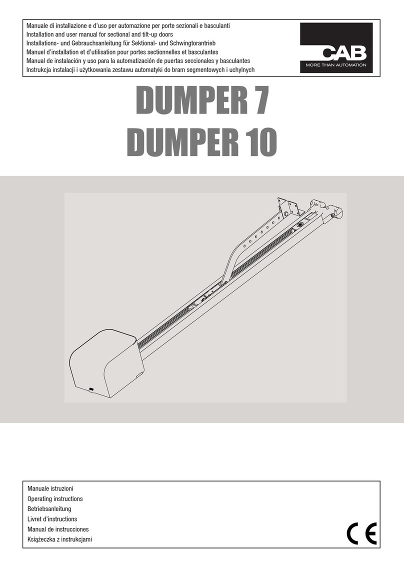
CAB DUMPER User manual

Manuale di installazione e d’uso per automazione per porte sezionali e basculanti
Installation and user manual for sectional and tilt-up doors
Installations- und Gebrauchsanleitung für Sektional- und Schwingtorantrieb
Manuel d’installation et d’utilisation pour portes sectionnelles et basculantes
Manual de instalación y uso para la automatización de puertas seccionales y basculantes
Instrukcja instalacji i użytkowania zestawu automatyki do bram segmentowych i uchylnych
DUMPER
myone S.r.l - Via T. Edison, 11 - 30035 Mirano (VE) - ITALY Tel. +39 041 412542 - Fax +39 041 412542
www.myoneautomation.com
Manuale di installazione e manutenzione automazione
per porte sezionali e basculanti
IT DUMPER
Manuale istruzioni
Operating instructions
Betriebsanleitung
Livret d’instructions
Manual de instrucciones
Książeczka z instrukcjami


3
1
2
200
190
72
119
31.5
1
2 3
4
5
6
o
7
8

4
3
4
5
- 6 -
4. Installazione meccanica
==
==
==
==
~ 600 mm
MOTOR
- 6 -
4. Installazione meccanica
==
==
==
==
~ 600 mm
MOTOR
- 6 -
4. Installazione meccanica
==
==
==
==
~ 600 mm
MOTOR
110 mm

5
6
7
- 7 -
min. 10 mm
4. Installazione meccanica
- 7 -
min. 10 mm
4. Installazione meccanica

6
8 9
11
13
10
12
LN
115 / 230 V.a.c. 50/60Hz

7
14
15
F1
1.6A
F2
8A
F2= FUSE 8AT
F1= FUSE 1.6AT
1 2 3 4 5 6 7
ON
OFF
DIP SWITCH
8
min.
max.
LED POWER
OPEN
FOTO
STOP
COM
-24 V
LAMP
+24 V
LAMP
SIG.
ANT.
NC NC
OPEN PROG. MEMO RX
Max
3W
NO

8
~ 45°
~ 45°
16

9
17
Mettere a piombo il braccio.
Level the arm.
Arm lotrecht stellen.
Mettre à plomb le bras.
Aplomar bien el brazo.
Ustawić ramię w pozycji
pionowej.
Braccio per porte a contrappesi art. AU.C25.
Overhead doors with balanceweights: special arm art. AU.C25.
Kipptor mit Gegengewichten: Sonderarm, Teil AU.C25.
Portes basculantes à contrepoids: bras spécial art. AU.C25.
Brazo para puerta de contrapesos art. AU.C25.
Ramię dla bram z przeciwwagą art. AU.C25.
Rotaia.
Rail.
Schiene.
Morceau de rail.
Guía.
Szyna. Regolare
Adjust
Regulieren
Régler
Regulación
Regulowanie.
Vite M6x35 UNI 5931
Screw M6x35 UNI 5931
Schraube M6x35 UNI 5931
Vis M6x35 UNI 5931
Tornillo M6x35 UNI 5931
Śruba M6x35 UNI 5931.
A porta chiusa lasciare 2 ÷ 3 cm.
Keep a distance of 2 ÷ 3 cm when the door is closed.
Wenn die Tür geschlossen ist, lassen 2 ÷ 3 cm.
Il faut lasser 2 ÷ 3 cm quand la porte est ouvert.
Cuando la puerta ésta cerrada, hay que haber 2 ÷ 3 cm.
Podczas zamkniętej bramy pozostawić 2 ÷ 3 cm.
Fissare il braccio sul filo superiore della porta.
Fix the arm to the top edge of the door.
Arm an der oberen Kante des Tores befestigen
Fixer le bras sur l’arête supérieure de la porte.
Fijar el brazo en la arista superior de la puerta.
Przymocować ramię do górnego prętu bramy.

10
18
+ BAT
- BAT
+
-

11
Dichiarazione CE di Conformità
Dichiarazione in accordo alle Direttive 2004/108/CE(EMC); 2006/95/CE(LVD)
Fabbricante:
AUTOMATISMI CAB Srl
Indirizzo:
Via della Tecnica,10 (z.i.) - 36010 Velo d’Astico (VI) - Italia
Dichiara che il prodotto:
Automazione a traino per porte sezionali modello:
DUMPER.
è conforme alle condizioni delle seguenti Direttive CE:
• DIRETTIVA 2004/108/CE DEL PARLAMENTO EUROPEO E DEL CONSIGLIO del 15 dicembre 2004 concernente il ravvici-
namento delle legislazioni degli Stati membri relative alla compatibilità elettromagnetica e che abroga la direttiva 89/336/CEE, secondo le
seguenti norme armonizzate:
EN 61000-6-2:2005, EN 61000-6-3:2007.
• DIRETTIVA2006/95/CE DELPARLAMENTO EUROPEO E DELCONSIGLIO del 12 dicembre 2006 concernente il ravvicinamento
delle legislazioni degli Stati membri relative al materiale elettrico destinato ad essere adoperato entro taluni limiti di tensione, secondo le
seguenti norme armonizzate:
EN 60335-1:2002 + A1:2004 + A11:2004 + A12:2006 + A2:2006 + A13:2008; EN 60335-2-103:2003.
• DIRETTIVA 2006/42/CE DEL PARLAMENTO EUROPEO E DEL CONSIGLIO del 17 maggio 2006 relativa alle macchine e che
modifica la direttiva 95/16/CE, rispettando i requisiti per le “quasi macchine”, secondo la seguente norma: EN13241-1:2003.
• AUTOMATISMI CAB Srl dichiara, inoltre, che la documentazione tecnica pertinente è stata compilata in conformità all’allegato VII
B della direttiva 2006/42/CE e che sono stati rispettati i seguenti requisiti essenziali: 1.1.1 - 1.1.2 - 1.1.3 - 1.1.5 - 1.2.1 - 1.2.3 - 1.2.6 - 1.3.1
- 1.3.2 - 1.3.3 - 1.3.4 - 1.3.7 - 1.3.9 - 1.5.1 - 1.5.2 - 1.5.4 - 1.5.5 - 1.5.6 - 1.5.7 - 1.5.8 - 1.5.10 - 1.5.11 - 1.5.13 - 1.6.1 - 1.6.2 - 1.6.4 - 1.7.2 -
1.7.4 - 1.7.4.1 - 1.7.4.2 - 1.7.4.3.
• Il produttore si impegna a trasmettere alle autorità nazionali, in risposta ad una motivata richiesta, le informazioni pertinenti sulla “quasi
macchina”. L’impegno comprende le modalità di trasmissione e lascia impregiudicati i diritti di proprietà intellettuale del fabbricante della
“quasi macchina”.
• Si comunica che la “quasi macchina” non deve essere messa in servizio finché la macchina finale in cui deve essere incorporata non è
stata dichiarata conforme, se del caso, alle disposizioni della direttiva 2006/42/CE.
• Inoltre il prodotto, limitatamente alle parti applicabili, risulta conforme alle seguenti norme:
EN 12445:2002, EN 12453:2002, EN 12978:2003.
Benincà Luigi, Responsabile legale.
Velo d’Astico, 02/11/2010.
E' vietato l'utilizzo del prodotto per scopi o con modalità
non previste nel presente manuale. Usi non corretti posso-
no essere causa di danni al prodotto e mettere in pericolo
persone e cose.
Si declina ogni responsabilità dall'inosservanza della buona
tecnica nella costruzione dei cancelli, nonché dalle defor-
mazioni che potrebbero verificarsi durante l'uso.
Conservare questo manuale per futuri utilizzi.
L'installazione deve essere effettuata da personale quali-
ficato nel pieno rispetto delle normative vigenti.
I materiali dell'imballaggio non devono essere lasciati alla
portata dei bambini in quanto fonte di potenziale pericolo.
Non disperdere nell'ambiente i materiali di imballo, ma se-
parare le varie tipologie (es. cartone, polistirolo) e smaltirle
secondo le normative locali.
L’installatore deve fornire tutte le informazioni relative
al funzionamento automatico, manuale e di emergenza
dell'automazione, e consegnare all’utilizzatore dell’impian-
to le istruzioni d’uso.
Questo prodotto non è destinato a essere utilizzato da
persone (bambini inclusi) con capacità fisiche, sensoriali o
mentali ridotte, o con mancanza di conoscenze adeguate,
AVVERTENZE
a meno che non siano sotto supervisione o abbiano rice-
vuto istruzioni d’uso da persone responsabili della loro
sicurezza.
•Prevedere sulla rete di alimentazione un inter-
ruttore/sezionatore onnipolare con distanza
d’apertura dei contatti uguale o superiore a 3 mm.
Verificare che a monte dell’impianto elettrico vi sia un interrut-
tore differenziale e una protezione di sovracorrente adeguati.
Alcune tipologie di installazione richiedono il collegamento
dell'anta ad un impianto di messa a terra rispondente alle
vigenti norme di sicurezza.
Durante gli interventi di installazione, manutenzione e ri-
parazione, togliere l’alimentazione prima di accedere alle
parti elettriche.
Le descrizioni e le illustrazioni presenti in questo manuale
non sono impegnative. Lasciando inalterate le caratte-
ristiche essenziali del prodotto il fabbricante si riserva il
diritto di apportare qualsiasi modifica di carattere tecnico,
costruttivo o commerciale senza impegnarsi ad aggiornare
la presente pubblicazione.

12
INTRODUZIONE
Ci congratuliamo con Voi per aver scelto il motoriduttore DUMPER.
Tutti gli articoli della vasta gamma CAB sono il frutto di una ventennale esperienza nel settore degli automatismi e di una
continua ricerca di nuovi materiali e di tecnologie all’avanguardia.
Proprio per questo, oggi siamo in grado di offrire dei prodotti estremamente affidabili che, grazie alla loro potenza, efficacia
e durata, soddisfano pienamente le esigenze dell’utente finale.
Tutti i nostri prodotti sono coperti da garanzia.
Inoltre, una polizza R. C. prodotti stipulata con primaria compagnia assicurativa copre eventuali danni a cose o persone
causati da difetti di fabbricazione.
NOTIZIE GENERALI
L’automatismo è concepito per motorizzare porte sezionali; per essere applicato su porte basculanti necessita di uno
speciale braccio di attacco (art. AU.C25).
In ogni caso dovranno essere assolte le seguenti condizioni:
- la distanza tra il punto più alto della porta ed il soffitto deve essere almeno 40mm;
- la porta deve potersi aprire e chiudere tirando e spingendo orizzontalmente sul suo bordo superiore;
- le manovre manuali devono risultare dolci e regolari.
DIMENSIONI
In figura 1 sono indicate le dimensioni espresse in millimetri
INSTALLAZIONE TIPO
In figura 2 è rappresentata una tipica installazione.
Rif. Articolo Descrizione
1 DUMPER Automazione 700N porte sezionali e basculanti
2 Guida traino 3000 mm
3 DUMPER.BAT Kit batterie di emergenza
4 PUPILLA -C Fotocellule per montaggio a parete
5 Costa di sicurezza
6 T2WV-C - T4WV-C Telecomando 2/4 CH - codifica rolling-code 433.92 MHz.
7 Sblocco di sicurezza
8 FBY Lampeggiante LED
ATTENZIONE:.
Il collegamento alla rete deve essere eseguito su canale indipendente e separato dai dispositivi di comando e sicurezza.
INSTALLAZIONE DELL’AUTOMAZIONE
Eseguire 2 fori perfettamente centrati sulla mezzeria della porta, come indicato in figura 3.
Fissare provvisoriamente la rotaia alla parete utilizzando due tasselli con relative viti, come indicato in figura 4. La rotaia
deve essere libera di muoversi verso il soffitto.
Con riferimento alla figura 5, applicare la piastrina di sostegno alla rotaia alla distanza di circa 60 cm dal motore, quindi
piegare (tenendo conto della distanza tra rotaia e parete) le due staffe per il fissaggio a soffitto e applicarle alla piastrina
di sostegno.
Sollevare la rotaia come indicato in figura 6 e facendo riferimento al disegno di figura 7 fissare le staffe a soffitto. La rotaia
deve essere perfettamente orizzontale. Fissare la rotaia alla parete e la staffa di traino al bordo superiore della porta. Tra
il profilo superiore della porta e la rotaia deve risultare una distanza minima di 10mm.
Aprire la copertura (figura 8) e rimuovere le due viti evidenziate in figura 9, quindi sfilare la piastra di blocco (figura 10).
Applicare il motore al binario (figura 11), reinserire la piastra di blocco e riavvitare le due viti (figura 12).
E’ ora possibile procedere con il collegamento elettrico utilizzando il cavo precablato alla centrale di comando (figura13).
E’ obbligatorio effettuare il collegamento di terra (GND) nel rispetto delle normative vigenti.
IMPORTANTE
A porta completamente chiusa, la staffa di trascinamento deve trovarsi a circa 45° rispetto alla rotaia come indicato in
Figura 16. A tal fine è’ possibile accorciare la staffa ed utilizzare le altre forature.

13
COLLEGAMENTI ELETTRICI (FIGURA 14)
Descrizione delle morsettiere
Ingresso Descrizione
OPEN-COM Ingresso pulsante OPEN (N.O.) per il comando dell’automazione, configurabile tramite il DIP1
FOTO-COM Ingresso contatto (N.C.) per dispositvi di sicurezza (Fotocellula)
STOP-COM Ingresso contatto (N.C.) per pulsante di arresto di emergenza (STOP)
ANT-COM Ingresso per antenna del radioricevitore incorporato con frequenza 433,92Mhz (Ant: segnale - COM:Calza)
LAMP/LAMP+24 Uscita 24V per collegamento lampeggiante di segnalazione
In figura 15 sono evidenziate le numerose predisposizioni da aprire secondo le necessità per il passaggio dei cavi di col-
legamento.
DESCRIZIONE DEI DIP-SWITCH DI CONFIGURAZIONE
Nota: Le modifiche alle impostazioni dei DIP-SWITCH vanno effettuate a porta completamente chiusa o, in alternativa, è
necessario togliere e ripristinare l’alimentazione di rete per rendere effettive le modifiche.
DIP1: Configurazione sequenza comandi ingresso OPEN
ON: Apre-Stop-Chiude-Stop-Apre...
OFF: Apre-Chiude-Apre...
DIP2: Configurazione richiusura automatica
ON: Richiusura automatica abilitata
OFF: Richiusura automatica disabilitata
DIP3: Selezione velocità in fase di rallentamento
ON: velocità in rallentamento bassa
OFF: velocità in rallentamento alta
DIP4: Apertura condominiale
ON: Apertura condominiale attiva, durante la fase di apertura, ulteriori comandi di apertura (pulsante o trasmettitori) non
hanno effetto.
OFF: Apertura condominiale non attiva
DIP5: Tempo inversione in chiusura per tensionamento cinghia
ON: Tempo minimo
OFF: Tempo massimo
DIP6: Inversione in chiusura per tensionamento cinghia
ON: Inversione non attiva
OFF: Inversione attiva
DIP7: Frenatura
ON: 80%
OFF: 90%
DIP8: Configurazione ingresso FOTO
ON: Ingresso FOTO attivo in apertura e chiusura
OFF: Ingresso FOTO attivo solo in chiusura
TRIMMER
Il trimmer presente sulla centrale regola la sensibilità del sensore anti schiacciamento. Ruotando in senso orario aumenta
la sensibilità, viceversa diminuisce.
Al primo intervento del sensore, la centrale riapre totalmente, successivamente (se DIP2=ON) tenta una nuova manovra di
chiusura, in caso di nuovo intervento riapre per 3s e si pone in stato di STOP.
MANOVRA MANUALE
Nel caso di interruzione dell’energia elettrica, è possibile manovrare manualmente l’anta, tirando verso il basso il cordino
con la manopola rossa come indicato in figura 16.
Al ritorno dell’alimentazione di rete, la prima manovra ripristina automaticamente lo sblocco.
AUTOAPPRENDIMENTO
La centrale elettronica è progettata per autoprogrammarsi ed essere pronta all’uso appena collegata alla tensione di rete.
ATTENZIONE: la procedura di autoapprendimento necessita il collegamento di tutte le sicurezze; qualora una o più non
fossero usate, ponticellare il relativo ingresso al morsetto COM -24 V.
Premere il pulsante PROG. (si accende la luce di cortesia), premere pulsante OPEN, automaticamente la porta eseguirà
una manovra fino a chiusura completa. Trascorsi 2 secondi, la porta eseguirà una manovra fino alla massima apertura
desiderata (premi tasto OPEN per determinare apertura desiderata).
Da questo momento, (Dip 2 ON = chiusura automatica abilitata) inizia il conteggio in secondi per la chiusura automatica,

14
trascorso il tempo desiderato, premere il pulsante OPEN, la porta andrà in chiusura uscendo automaticamente dalla pro-
grammazione, calcolando velocità e rallentamenti da effettuare durante la manovra.
N.B. Il tempo chiusura automatica viene conteggiato dall’operatore e va da 0 a 90 secondi. L’intera procedura di acquisi-
zione delle battute viene eseguita a bassa velocità.
Con il Dip 2 OFF = chiusura automatica disabilitata, l’apertura, la chiusura e lo stop vengono effettuate tramite radioco-
mando e/o pulsante.
MEMORIZZAZIONE TRASMETTITORE
A porta chiusa, mantenere premuto il pulsante MEMO RX, premere il tasto desiderato del trasmettitore entro 5 sec., la luce
di cortesia lampeggia per avvenuta memorizzazione.
Ripetere l’operazione ad ogni trasmettitore. MAX 20 codici diversi.
ANNULLAMENTO DI UN TRASMETTITORE: mantenere premuto il pulsante MEMO RX fino all’accensione della luce di
cortesia, premere il pulsante del trasmettitore, seguono 3 “LAMPEGGI” di conferma annullamento - rilasciare il pulsante
MEMO RX
RESET SCHEDA ACQUISIZIONE CODICI: resetta la memoria annullando tutti i codici memorizzati - mantenere premuto il
pulsante MEMO RX fino allo spegnimento della “LUCE DI CORTESIA”
- seguono 9 “LAMPEGGI” di conferma reset totale - rilasciare il pulsante MEMO RX.
INDICAZIONI DELLA LUCE DI CORTESIA
nessun “LAMPEGGIO” = trasmettitore da memorizzare.
1 “LAMPEGGIO” = trasmettitore memorizzato.
2 “LAMPEGGI” = se si ripete la memorizzazione di un trasmettitore già memorizzato.
3 “LAMPEGGI” = dopo l’annullamento di un trasmettitore.
4 “LAMPEGGI” = in modalità “annullamento” trasmettitore non memorizzato.
5 “LAMPEGGI” = memoria scheda esaurita.
9 “LAMPEGGI” = annullamento di tutti i codici in memoria.
ACCESSORI OPZIONALI
Porte basculanti
E’ possibile installare l’automazione DUMPER anche su porte basculanti, in questo caso è necessario l’apposito adattatore
AU.C25 da installare sulla porta come indicato in figura 17.
Kit batterie di emergenza
E’ disponibile il kit batterie di emergenza (cod. DUMPER.BAT )che consente il funzionamento dell’automazione anche in
caso di mancanza di alimentazione di rete.
Inserire le batterie negli appositi vani e collegarle alla centrale come indicato in Figura 18.
DATI TECNICI DUMPER
Alimentazione 115 ÷ 230Vac 50/60 Hz
Assorbimento 1 A
Assorbimento in Stand-by 1W senza accessori
3W con accessori
Forza Trazione/Spinta 700 N
Corsa massima 2600 mm
Alimentazione accessori 24 V =/0,5A max
Velocità apertura 0,12 - 0,20 m/s
Velocità chiusura 0,12 - 0,20 m/s
Portata massima 9 mq
Intermittenza lavoro Uso Intensivo
Temp. funzionamento -20°C/+50°C
Grado di protezione IP 10
Peso 1,6 kg

15
EC Declaration of Conformity
Directive 2004/108/EC(EMC); 2006/95/EC (LVD)
Manufacturer:
AUTOMATISMI CAB Srl.
Address:
Via della Tecnica,10 (z.i.) - 36010 Velo d’Astico (VI) – Italy
It is hereby stated that the product
pulling automatic system for sectional doors model
DUMPER.
is compliant with provisions set forth in the following EC Directives:
- DIRECTIVE 2004/108/EC OF THE EUROPEAN PARLIAMENT AND OF THE COUNCIL of 15 December 2004, on the harmonisa-
tion of the laws of Member States relating to electromagnetic compatibility and which cancels Directive 89/336/EEC, according to the following
harmonised regulations: EN 61000-6-2:2005, EN 61000-6-3:2007.
- DIRECTIVE 2006/95/EC OF THE EUROPEAN PARLIAMENTAND OF THE COUNCILof 12 December 2006, on the harmonisation
of the laws of Member States relating to electrical equipment designed for use with certain voltage limits, according to the following harmonised
regulations: EN 60335-1:2002 + A1:2004 + A11:2004 + A12:2006 + A2:2006 + A13:2008; EN 60335-2-103:2003.
- DIRECTIVE 2006/42/EC OF THE EUROPEAN PARLIAMENTAND OF THE COUNCIL of 17 May 2006, on machinery, which amends
Directive 95/16/EC, and complies with the requisites for the “partly completed machinery (almost machinery)” set forth in the EN13241-1:2003
regulation.
• Moreover, AUTOMATISMI CAB Srl declares that the pertaining technical documentation has been drawn up in compliance with Attach-
ment VII B of the 2006/42/ EC Directive and that the following requirements have been complied with: 1.1.1 - 1.1.2 - 1.1.3 - 1.1.5 - 1.2.1 - 1.2.3
- 1.2.6 - 1.3.1 - 1.3.2 - 1.3.3 - 1.3.4 - 1.3.7 - 1.3.9 - 1.5.1 - 1.5.2 - 1.5.4 - 1.5.5 - 1.5.6 - 1.5.7 - 1.5.8 - 1.5.10 - 1.5.11 - 1.5.13 - 1.6.1 - 1.6.2 - 1.6.4
- 1.7.2 - 1.7.4 - 1.7.4.1 - 1.7.4.2 - 1.7.4.3.
• The manufacturer undertakes that information on the “partly completed machinery” will be sent to domestic authorities. Transmission ways
are also included in the undertaking, and the Manufacturer’s intellectual property rights of the “almost machinery” are respected.
• It is highlighted that commissioning of the “partly completed machinery” shall not be provided until the nal machinery, in which it should
be incorporated, is declared compliant, if applicable, with provisions set forth in the Directive 2006/42/EC on Machinery.
• Moreover, the product, as applicable, is compliant with the following regulations:
EN 12445:2002, EN 12453:2002, EN 12978:2003.
Benincà Luigi, Legal Ofcer.
Velo d’Astico, 22 November 2010.
The product shall not be used for purposes or in ways
other than those for which the product is intended for and
as described in this manual. Incorrect uses can damage
the product and cause injuries and damages.
The company shall not be deemed responsible for the non-
compliance with a good manufacture technique of gates as
well as for any deformation, which might occur during use.
Keep this manual for further use.
Qualified personnel, in compliance with regulations in force,
shall insta ll the system.
Packaging must be kept out of reach of children, as it can
be hazardous. For disposal, packaging must be divided
the various types of waste (e.g. carton board, polystyrene)
in compliance with regulations in force.
The installer must supply all information on the automatic,
manual and emergency operation of the automatic system
and supply the end user with instructions for use.
This product is not to be used by persons (including chil-
dren) with reduced physical, sensory or mental capacity, or
who are unfamiliar with such equipment, unless under the
WARNING
supervision of or following training by persons responsible
for their safety.
•An omnipolar switch/section switch with remote
contact opening equal to, or higher than 3mm
must be provided on the power supply mains..
Make sure that before wiring an adequate differential
switch and an overcurrent protection is provided.
Pursuant to safety regulations in force, some types of
installation require that the gate connection be earthed.
During installation, maintenance and repair, cut off power
supply before accessing to live parts.
Descriptions and figures in this manual are not binding.
While leaving the essential characteristics of the product
unchanged, the manufacturer reserves the right to modify
the same under the technical, design or commercial point
of view without necessarily update this manual.

16
INTRODUCTION
Thank you for choosing our DUMPER ratiomotor.
All items in the wide CAB production range are the result of twenty-years’ experience in the automatism sector and of
continuous research for new materials and advanced technologies.
We are, therefore, in the position to offer highly reliable products that due to their power, effectiveness and useful life, fully
satisfy the final user’s requirements.
All our products are covered by warranty.
Possible injury to people or accidents caused by defects in construction are covered by a civil liability policy drawn up with
one of the major insurance companies.
GENERAL INFORMATION
The system has been studied to motorize sectional doors.
To be applied onto balancing doors, a special fitting arm is required (item AU.C25).
In any case, following conditions will have to be observed:
- the distance between the door highest point and the ceiling must be at least 40mm (fig. 2).
- it has to be possible to open and close the door by pulling and pushing horizontally its top edge (fig.2).
- manual moves must be smooth and regular.
DIMENSIONS
Figure 1 shows the dimensions, in mm
TYPICAL INSTALLATION
Figure 2 illustrates a typical installation.
Ref. Item Description
1 DUMPER 700N automation for sectional and tilt-up doors
2 Drive guide 3000 mm
3 DUMPER.BAT Emergency battery kit
4 PUPILLA -C Wall mounting photocell
5 Safety rail
6 T2WV-C - T4WV-C 2/4 CH remote control - coding: rolling-code 433.92 MHz.
7 Safety release
8 FBY LED flasher
CAUTION:
The mains connection must be made using a separate channel, independent of the control and safety equipment.
INSTALLING THE AUTOMATION
Drill 2 holes at the exact centre of the door, as shown in figure 3.
Provisionally mount the track to the wall with two anchor bolts, as shown in figure 4. The track must be free to move to-
wards the ceiling.
As shown in figure 5, fit the mounting plate to the track at about 60 cm from the motor, then, in relation to the distance
between the track and wall, fold the two ceiling brackets and secure them to the mounting plate.
Raise the track as shown in figure 6 and secure the brackets to the ceiling (see figure 7). The track must be perfectly hori-
zontal. Secure the track to the wall, and the drive bracket to the top edge of the door. There must be a gap of at least 10
mm between the top edge of the door and the track.
Open the cover (figure 8) and remove the two bolts indicated in figure 9, then extract the lock plate (figure 10). Fit the motor
to the rail (figure 11), restore the lock plate, and screw the two bolts in again (figure 12).
You can now make the electrical connection; use the cable already wired to the control unit (figure 13).
The system must be grounded (GND) as required by established regulations.
IMPORTANT
When the door is fully closed, the drive bracket must be at an angle of about 45° to the track, see Figure 16. If necessary,
shorten the bracket and use the other mounting holes.

17
ELECTRICAL CONNECTIONS (FIGURE 14)
Terminal blocks
Input Description
OPEN-COM N.O. OPEN button input for automation control, can be set with DIP1
FOTO-COM N.C. contact input for safety equipment (photocell)
STOP-COM N.C. contact input for emergency stop button (STOP)
ANT-COM Input for integrated RF receiver antenna, frequency 433.92 MHz (Ant: signal - COM: shield)
LAMP/LAMP+24 24V output for warning flasher
Figure 15 shows the holes which can be opened for routing the cables, as required.
DIPSWITCH CONFIGURATION
Note: Only change the dip switch settings with the door completely closed; alternatively, shut off/restore power to apply
the changed settings.
DIP1: OPEN input command sequence
ON: Open-Stop-Close-Stop-Open...
OFF: Open-Close-Open...
DIP2: Auto close
ON: Auto close enabled
OFF: Auto close disabled
DIP3: Ramp down speed
ON: Low ramp down speed
OFF: High ramp down speed
DIP4: Condominium open
ON: Condominium open enabled; while the door is opening, subsequent open commands (button or remote) will have no
effect.
OFF: Condominium open disabled
DIP5: Reverse time when closing to tension belt
ON: Minimum time
OFF: Maximum time
DIP6: Reverse when closing to tension belt
ON: Reverse disabled
OFF: Reverse enabled
DIP7: Braking
ON: 80%
OFF: 90%
DIP8: FOTO input
ON: FOTO input enabled when opening and closing
OFF: FOTO input enabled only when closing
TRIMMER
The trimmer on the control unit adjusts the sensitivity of the anticrushing sensor.By turning it clockwise the sensitivity of
the sensor is increased and when the trimmer is turned counterclockwise the sensitivity decreases.
After the first sensor intervention the control unit fully opens the leaf ;afterwards (if DIP2=ON) the control unit attempts another
closing maneuver,in case of sensor intervention during this phase the control unit opens the leaf for 3 s and than stops it.
MANUAL CONTROL
If mains power fails, the door can be operated manually with the rope with the red handle shown in figure 16.
When power is restored, the first command automatically resets the release.
SELF TEACH
The electronic control unit is designed to program itself and be ready for use as soon as mains power is available.
CAUTION: the self teach procedure requires all safety equipment to be hooked up; if any such equipment is not installed
and hooked up, fit a jumper to the COM -24 V input terminal.
Press PROG. (the courtesy light turns on), then OPEN; the door will close completely. After 2 seconds, it will open to the
full extent desired (press OPEN to set the fully open position).
Now (with Dip 2 ON = auto close enabled) the auto close delay starts; wait for a suitable amount of time to pass, then
press OPEN, the door will close, quit programming mode, and calculate the speeds and decelerations (ramp down) used
during its cycle.

18
N.B.: the auto close delay is set by the operator, in a range of 0 - 90 seconds. The entire programming procedure is run
at low speed.
With Dip 2 OFF = auto close disabled, the open, close and stop commands are sent with the remote control or button.
MEMORIZING TRANSMITTERS
With the door closed, hold down MEMO RX and press the desired transmitter button within 5 sec.; the courtesy lamp will
flash to confirm memorization.
Repeat for each separate transmitter. Up to 20 different codes can be stored in this way.
TO DELETE A TRANSMITTER: hold down MEMO RX until the courtesy light turns on, then press the transmitter button;
the courtesy light flashes 3 times to confirm the deletion - now release the MEMO RX button.
RESETTING MEMORY: resets memory by deleting all memorized codes - hold down MEMO RX until the courtesy light
goes out
- the courtesy light flashes 9 times to confirm that the memory has been reset - now release the MEMO RX button.
COURTESY LIGHT SIGNALS
no FLASH = transmitter to memorize.
1 FLASH = transmitter memorized.
2 FLASHES = a previously memorized transmitter is being re-memorized.
3 FLASHES = a transmitter has been deleted.
4 FLASHES = in delete mode, transmitter not memorized.
5 FLASHES = memory full.
9 FLASHES = all memorized codes deleted.
OPTIONAL ACCESSORIES
Tilt-up doors
The DUMPER automation can also be installed to tilt-up doors; in this case you must install the AU.C25 adapter to the
door as shown in figure 17.
Emergency battery kit
An emergency battery kit is available (code DUMPER.BAT) to allow the automation to work even during mains power failures.
Fit the batteries in their compartments and hook them up as shown in Figure 18.
TECHNICAL DATA DUMPER
Power 115 - 230V AC 50/60 Hz
Power draw 1 A
Standby power draw 1W without accessories
3W with accessories
Traction/thrust 700 N
Maximum stroke 2600 mm
Accessory power 24 V =/O.5A max
Opening speed 0.12 - 0.20 m/s
Closing speed 0.12 - 0.20 m/s
Maximum load 9 sqm
Intermittency Intensive Use
Operating temperature -20°C/+50°C
Protection rating IP 10
Weight 1.6 kg

19
EG-Konformitätserklärung
Erklärung gemäß Richtlinie 2004/108/CE(EMV); 2006/95/CE(LVD)
Hersteller:
AUTOMATISMI CAB Srl
Adresse:
Via della Tecnica,10 (z.i.) - 36010 Velo d’Astico (VI) - Italien
Erklärt, dass das Produkt:
Automatische Schleppvorrichtung für sektionale Türen:
DUMPER.
folgenden EG-Richtlinien entspricht:
• RICHTLINIE 2004/108/EG DES EUROPÄISCHEN PARLAMENTS UND DES RATES vom 15. Dezember 2004 zur Angleichung
der Rechtsvorschriften der Mitgliedstaaten über die elektromagnetische Verträglichkeit und zur Aufhebung der Richtlinie 89/336/EWG, gemäß
nachstehenden Normen:
EN 61000-6-2:2005, EN 61000-6-3:2007.
• RICHTLINIE 2006/95/EG DES EUROPÄISCHEN PARLAMENTS UND DES RATES vom 12. Dezember 2006 zur Angleichung der
Rechtsvorschriften der Mitgliedstaaten betreffend elektrische Betriebsmittel zur Verwendung innerhalb bestimmter Spannungsgrenzen, gemäß
nachstehenden Normen:
EN 60335-1:2002 + A1:2004 + A11:2004 + A12:2006 + A2:2006 + A13:2008; EN 60335-2-103:2003.
• RICHTLINIE 2006/42/EG DES EUROPÄISCHEN PARLAMENTS UND DES RATES vom 17. Mai 2006 über Maschinen, zur Auf-
hebung der Richtlinie 95/16/EG, gemäß Anforderungen für „unvollständige Maschinen“ und nachstehender Norm: EN13241-1:2003.
• AUTOMATISMI CAB Srl erklärt, dass die technischen Unterlagen gemäß Anhang VII Teil B der Richtlinie 2006/42/EG erstellt wurden
und dass das Produkt folgenden Anforderungen entspricht: 1.1.1 - 1.1.2 - 1.1.3 - 1.1.5 - 1.2.1 - 1.2.3 - 1.2.6 - 1.3.1 - 1.3.2 - 1.3.3 - 1.3.4 - 1.3.7
- 1.3.9 - 1.5.1 - 1.5.2 - 1.5.4 - 1.5.5 - 1.5.6 - 1.5.7 - 1.5.8 - 1.5.10 - 1.5.11 - 1.5.13 - 1.6.1 - 1.6.2 - 1.6.4 - 1.7.2 - 1.7.4 - 1.7.4.1 - 1.7.4.2 - 1.7.4.3.
• Der Hersteller verpichtet sich die Informationen zu der „unvollständigen Maschine“ einzelstaatlichen Stellen auf begründetes Verlangen zu
übermitteln. Durch die Übermittlung bleibt das intellektuelle Eigentum des Herstellers der „unvollständigen Maschine“ unberührt.
• Diese „unvollständige Maschine“ darf erst dann in Betrieb genommen werden, wenn gegebenenfalls festgestellt wurde, dass die Maschine,
in die die unvollständige Maschine eingebaut werden soll, den Bestimmungen der Maschinenrichtlinie 2006/42/EG entspricht.
• Das Produkt entspricht außerdem, falls zutreffend, folgenden Normen:
EN 12445:2002, EN 12453:2002, EN 12978:2003.
Benincà Luigi, Rechtsvertreter
Velo d’Astico, 02/11/2010.
Das Produkt darf nicht für andere Zwecke oder auf andere
Weise verwendet werden, als in der vorliegenden Anlei-
tung beschrieben. Ein ungeeigneter Gebrauch kann das
Produkt beschädigen und eine Gefahr für Personen und
Sachen darstellen.
Wir übernehmen keinerlei Haftung für Schäden, die sich aus
einer unsachgerechten Montage der Tore und aus daraus
folgenden Verformungen ergeben können.
Bewahren Sie dieses Handbuch für Nachschlagzwecke auf.
Die Installation darf nur von qualifizierten Fachleuten laut
den geltenden Vorschriften vorgenommen werden.
Das Verpackungsmaterial fern von Kindern halten, da es
eine potentielle Gefahr darstellt. Das Verpackungsmaterial
nicht ins Freie werfen, sondern je nach Sorte (z.B. Pappe,
Polystyrol) und laut den örtlich geltenden Vorschriften
entsorgen.
Der Installateur hat dem Benutzer alle Informationen über
den automatischen, manuellen Betrieb sowie den Not-
Betrieb der Automatik zusammen mit der Bedienungsanlei-
tung zu liefern.
Dieses Produkt eignet sich nicht für den Gebrauch durch
Personen (einschließlich Kindern) mit eingeschränkten
körperlichen, sensorischen oder geistigen Fähigkeiten oder
HINWEISE
ohne die nötigen Kenntnisse, es sei denn, sie werden von
für ihre Sicherheit verantwortlichen Personen beaufsich-
tigt oder angeleitet.
•Das Stromnetz muss mit einem allpoligen Schal-
ter bzw. Trennschalter ausgestattet sein, dessen
Kontakte einen Öffnungsabstand gleich oder
größer als 3 aufweisen. Kontrollieren, ob der elektrischen
Anlage ein geeigneter Differentialschalter und ein Über-
spannungsschutzschalter vorgeschaltet sind.
Einige Installationstypologien verlangen den Anschluss
des Flügels an eine Erdungsanlage laut den geltenden
Sicherheitsnormen.
Während der Installation, der Wartung und der Reparatur,
die Anlage stromlos machen bevor an den elektrischen
Teilen gearbeitet wird.
Die in diesem Handbuch enthaltenen Beschreibungen und
Abbildungen sind nicht verbindlich. Ausgenommen der
Haupteigenschaften des Produkts, behält sich der Her-
steller das Recht vor eventuelle technische, konstruktive
oder kommerzielle Änderungen vorzunehmen ohne dass
er vorliegende Veröffentlichung auf den letzten Stand
bringen muss.

20
EINLEITUNG
Wir danken Ihnen dafür, daß Sie sich für das DUMPER Steuergehäuse entschieden haben.
Alle Produkte der umfangreichen CAB Produktion sind das Ergebnis der zwanzigjährigen Erfahrungen im Bereich der Au-
tomation und der ständigen Erforschung von neuen Materialien und fortgeschrittenen Technologien.
Aus diesem Grund sind wir heute in der Lage, zuverlässige Produkte anzubieten, die, dank ihren Stärke, Wirksamkeit und
Haltbarkeit, der Anforderungen des Endverbrauchers völlig gerecht werden.
Alle Produkte sind durch Garantie gedeckt.
Eventuelle Personen- oder Sachschäden, die durch Fertigungsfehler verursacht werden können, werden durch eine der
wichtigsten Versicherungsgesellschaften gedeckt.
ALLGEMEINE INFORMATION
Die Automatik bedient über einen Motor sektionale Türen; um an Schwenktüren installiert zu werden, muss ein spezieller
Arm angeschlossen werden (art. AU.C25).
Jedenfalls müssen folgende Bedingungen erfüllt werden:
- Der Abstand zwischen der höchsten Stelle des Tores und der Decke muß wenigstens 40mm sein (Abb. 2).
- das Tor muß zu öffnen und zu schließen sein, indem man es an seinem Oberrand zieht und schiebt (Abb. 2).
- Die Handgriffe müssen sanft und regelmäßig sein.
ABMESSUNGEN
In Abbildung 1 sind die Abmessungen in Millimetern angegeben.
TYPISCHE INSTALLATION
In Abbildung 2 ist eine typische Installation dargestellt.
Bez. Artikel Beschreibung
1 DUMPER Automatikantrieb 700N Sektional- und Schwingtore
2 Zugführung 3000mm
3 DUMPER.BAT Notfallbatterie-Kit
4 PUPILLA -C Fotozellen zur Wandmontage
5 Sicherheitskante
6 T2WV-C - T4WV-C Fernbedienung 2/4 CH - Rolling-Code-Kodierung 433.92 Mhz.
7 Sicherheitsentriegelung
8 FBY LED-Blinkleuchte
ACHTUNG:
Der Netzanschluss muss auf einem eigenen und von den Steuer- und Sicherheitsvorrichtungen getrennten Kanal ausgeführt
werden.
INSTALLATION DES AUTOMATIKANTRIEBS
Zwei perfekt zentrierte Löcher auf der Mittellinie des Tors bohren, wie in Abbildung 3 gezeigt.
Die Schiene provisorisch mit zwei Dübeln und passenden Schrauben an der Wand befestigen, wie in Abbildung 4 gezeigt.
Die Schiene muss sich frei in Richtung Decke bewegen lassen.
Wie in Abbildung 5 die Befestigungsplatte an der Schiene mit einem Abstand von zirka 60 cm vom Motor anbringen, dann
(unter Berücksichtigung des Abstands zwischen Schiene und Wand) die beiden Bügel zur Deckenbefestigung zurechtbiegen
und an der Befestigungsplatte anbringen.
Die Schiene wie in Abbildung 6 anheben und die Bügel wie in der Zeichnung von Abb. 7 an der Decke befestigen. Die
Schiene muss perfekt horizontal sein. Die Schiene an der Wand festschrauben und den Zugbügel am oberen Rand des
Tors befestigen. Zwischen dem oberen Profil des Tors und der Schiene muss ein Mindestabstand von 10 mm bestehen.
Die Abdeckung (Abb. 8) öffnen und die zwei in der Abb. 9 markierten Schrauben entfernen, dann das Blockierblech her-
ausziehen (Abb. 10). Den Motor an der Schiene anbringen (Abb. 11), das Blockierblech wieder einschieben und die beiden
Schrauben wieder festziehen (Abb. 12).
Jetzt können die elektrischen Anschlüsse ausgeführt werden, indem das bereits mit der Steuerzentrale verbundene Kabel
verwendet wird (Abb. 13).
Es ist zwingend notwendig, den Erdanschluss (GND) gemäß den geltenden Vorschriften auszuführen.
WICHTIG
Bei vollständig geschlossenem Tor muss der Schleppbügel in einem Winkel von zirka 45° zu der Schiene stehen, siehe
Abb. 16. Zu diesem Zweck kann der Bügel verkürzt und andere Löcher benutzt werden.
Table of contents
Languages:
Other CAB Garage Door Opener manuals
Popular Garage Door Opener manuals by other brands

Chamberlain
Chamberlain LiftMaster 3850PC owner's manual

Chamberlain
Chamberlain Security+ 1000SDC-R owner's manual

Rollerdor
Rollerdor RD55 user guide

krispol
krispol STARCUS K06/K10 manual

Aprimatic
Aprimatic SLIDE 230 Electrical installation, Use and Maintenance instructions

RCA
RCA Orca GarageAce Installation instructions & owner's manual