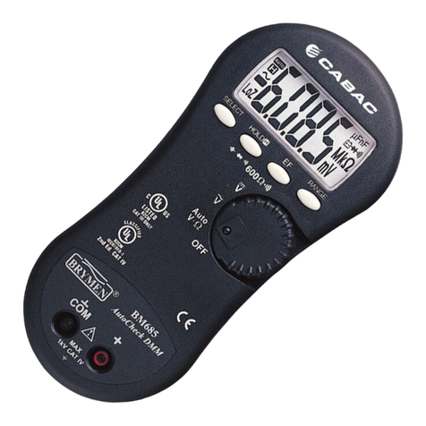
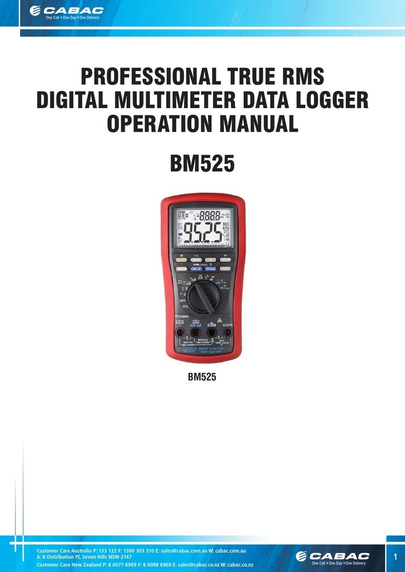
CABAC BM117 User manual

USER'S
MANUAL
BM117/BM118
Auto-CheckTM
Clamp-on Multimeter
Series
A: Distribution Pl, Seven Hills NSW 2147

1
1) SAFETY
This manual contains information and warnings that must be followed for operating the
instrument safely and maintaining the instrument in a safe operating condition. If the
instrument is used in a manner not specified by the manufacturer, the protection
provided by the instrument may be impaired.
The meter meets the requirements for double insulation to IEC61010-2-032(1994),
EN61010-2-032(1995), UL3111-2-032(1999):
Category III 600 Volts ac and dc.
PER IEC61010 OVERVOLTAGE INSTALLATION CATEGORY
OVERVOLTAGE CATEGORY II
Equipment of OVERVOLTAGE CATEGORY II is energy-consuming equipment to be
supplied from the fixed installation.
Note – Examples include household, office, and laboratory appliances.
OVERVOLTAGE CATEGORY III
Equipment of OVERVOLTAGE CATEGORY III is equipment in fixed installations.
Note – Examples include switches in the fixed installation and some equipment for
industrial use with permanent connection to the fixed installation.
OVERVOLTAGE CATEGORY IV
Equipment of OVERVOLTAGE CATEGORY IV is for use at the origin of the
installation. Note – Examples include electricity meters and primary over-current
protection equipment.
TERMS IN THIS MANUAL
WARNING identifies conditions and actions that could result in serious injury or even
death to the user.
CAUTION identifies conditions and actions that could cause damage or malfunction
in the instrument.
Customer Care Australia P: 13122 F: 1300 303 310 E: sales@cabac.com.au W:cabac.com.au
A: Distribution Pl, Seven Hills NSW 2147
1

2
WARNING
To reduce the risk of fire or electric shock, do not expose this product to rain or
moisture. The meter is intended only for indoor use.
To avoid electrical shock hazard, observe the proper safety precautions when working
with voltages above 60 VDC or 30 VAC rms. These voltage levels pose a potential
shock hazard to the user.
Inspect test leads, connectors, and probes for damaged insulation or exposed metal
before using the instrument. If any defects are found, replace them immediately.
Do not touch test lead tips or the circuit being tested while power is applied to the
circuit being measured. To avoid accidentally short circuit of bare (uninsulated)
hazardous live conductors or busbars, switch them off before insertion and removal of
the current clamp jaws. Contact with the conductor could result in electric shock. Keep
your hands/fingers behind the hand/finger barriers that indicate the limits of safe
access of the meter and the test leads during measurement.
CAUTION
Disconnect the test leads from the test points before changing meter functions.
INTERNATIONAL ELECTRICAL SYMBOLS
!Caution ! Refer to the explanation in this Manual
Caution ! Risk of electric shock
Earth (Ground)
Double Insulation or Reinforced insulation
Fuse
AC--Alternating Current
DC--Direct Current
2) CENELEC Directives
The instruments conform to CENELEC Low-voltage directive 73/23/EEC and
Electromagnetic compatibility directive 89/336/EEC
Customer Care Australia P: 13122 F: 1300 303 310 E: sales@cabac.com.au W:cabac.com.au
A: Distribution Pl, Seven Hills NSW 2147
2

3
3) PRODUCT DESCRIPTION
This user's manual uses only representative model(s) for illustrations. Please refer
specification details for function availability to each model.
1) Non-Contact EF-Detection (NCV):
antenna position
2) Jaw marking lines for ACA position
error indication
3) Hand/Finger Barrier to indicate the
limits of safe access to the jaws during
current measurements
4) Push-buttons for special functions
& features
5) Input Jack for all functions EXCEPT
non-invasive ACA current function
6) Common (Ground reference) Input
Jack for all functions EXCEPT
non-invasive ACA current function
7) Slide-switch Selector to turn the
power ON/OFF and Select a function
8) 3-5/6 digits 6000 counts LCD
display
9) Jaw trigger for opening the
transformer clamp jaws
10) Jaw center Indicators, at where
best ACA accuracy is specified
11) Transformer Clamp Jaws for AC
current magnetic field pick up
Customer Care Australia P: 13122 F: 1300 303 310 E: sales@cabac.com.au W:cabac.com.au
A: Distribution Pl, Seven Hills NSW 2147
3

4
4) OPERATION
ACA Current clamp-on function
Set the slide-switch function selector to the position. Inputs are made through the
clamp jaws for non-invasive ACA current measurements.
CAUTION
●Press the jaw trigger and clamp the jaws around only one single conductor of a circuit
for load current measurement. Make sure the jaws are completely closed, or else it will
introduce measurement errors. Enclosing more than one conductor of a circuit will
result in differential current (like identifying leakage current) measurement.
●Adjacent current-carrying devices such as transformers, motors and conductor wires
will affect measurement accuracy. Keep the jaws away from them as much as possible
to minimize influence.
Customer Care Australia P: 13122 F: 1300 303 310 E: sales@cabac.com.au W:cabac.com.au
A: Distribution Pl, Seven Hills NSW 2147
4

5
Hi-Z DCV, ACV & Line-Level Hz functions
Set the slide-switch function selector to the position selects common impedance
(Hi-Z) voltage measurements. Input impedance is set at approximately 5MΩto
minimize loading on circuits under tests. DCV is the default function. The DC
annunciator “ ” turns on. Press SELECT button momentarily to select ACV. The AC
annunciator “ ” turns on. Press momentarily again to activate the Line-Level Hz
function.
Note:
●Line-Level Hz input sensitivity varies automatically with ACV range selected when
Line-Level Hz is selected. AC 6V range has the highest and AC 600V range has the
lowest sensitivity. Measuring the signal in ACV function WHILE selecting Line-Level Hz
function in that ACV range automatically sets the most appropriate sensitivity for higher
voltage applications. This can avoid electrical noises as in 110/220V line voltage
applications for example. If the reading shows zero due to insufficient signal levels,
select Line-Level Hz function BEFORE making measurements (at AC 6V range) will set
the highest sensitivity.
Customer Care Australia P: 13122 F: 1300 303 310 E: sales@cabac.com.au W:cabac.com.au
A: Distribution Pl, Seven Hills NSW 2147
5

6
AutoCheckTM mode
Set the slide-switch function selector to the position. This innovative AutoCheckTM
feature automatically selects measurement function of DCV, ACV or Resistance (Ω)
based on the input via the test leads.
●With no input, the meter displays “Auto” when it is ready.
●With no voltage signal but a resistance below 6MΩis present, the meter displays the
resistance value. When below 25Ω(0.025kΩ) is present, the meter further gives a
continuity beep tone.
●When a signal above the threshold of +1.5 VDC, -1 VDC or 2 VAC up to the rated
600V is present, the meter displays the voltage value in appropriate DC or AC,
whichever larger in peak magnitude.
●Overload-Alert Feature: When above rated 600V is present, the meter displays “OL”
with a warning beep tone for over-range indication. Disconnect the test leads from the
signal immediately to avoid hazards.
Note:
●Range-Lock Feature: When a measurement reading is being displayed in
Customer Care Australia P: 13122 F: 1300 303 310 E: sales@cabac.com.au W:cabac.com.au
A: Distribution Pl, Seven Hills NSW 2147
6

7
AutoCheckTM mode, press the RANGE button momentarily 1 time can lock the
function-range it was in. The LCD annunciator “”turns off. Range-lock can
speed up repetitive measurements. Press the button momentarily repeatedly to step
through the ranges. Press and hold the button for 1 second or more to resume
AutoCheckTM mode.
●As Hazardous-Alert: When making resistance measurements in AutoCheckTM
mode, an unexpected display of voltage readings alerts you that the object under test is
being energized.
●Ghost-voltage buster: Ghost-voltages are unwanted stray signals coupled from
adjacent hard signals, which confuse common multimeter voltage measurements. Our
AutoCheckTM mode provides low (ramp-up) input impedance (approx. 1.6kΩat low
voltage) to drain ghost voltages leaving mainly hard signal values on meter readings. It
is an invaluable feature for precise indication of hard signals, such as distinguishing
between hot and open wires (to ground) in electrical installation applications.
WARNING:
●AutoCheckTM mode input impedance increases abruptly from initial 1.6kΩto a few
hundred kΩ’s on high voltage hard signals. “LoZ” displays on the LCD to remind the
users of being in such low impedance mode. Peak initial load current, while probing
directly to 600VAC for example, can be up to 530mA (600V x 1.414 / 1.6kΩ),
decreasing abruptly to approx. 4mA (600V x 1.414 / 210kΩ) within a fraction of a
second. Do not use AutoCheckTM mode on circuits that could be damaged by such low
input impedance. Instead, use slide-switch function selector common input
impedance voltage modes (Hi-Z of approx. 5MΩ) to minimize loading for such circuits.
Manual or Auto-ranging
When the function selected has more than one range, press the RANGE button
momentarily selects manual-ranging. The meter remains in the range it was in. The
LCD annunciator turns off. Press the button momentarily again to step
through the ranges. Press and hold the button for 1 second or more to resume
auto-ranging.
Note:
*Manual-ranging feature is not available to 600Ω//functions.
*To use Manual-ranging feature in AutoCheckTM mode, please see “Range-Lock
Feature” as explained in footnotes of AutoCheckTM mode section.
Customer Care Australia P: 13122 F: 1300 303 310 E: sales@cabac.com.au W:cabac.com.au
A: Distribution Pl, Seven Hills NSW 2147
7

8
Electric Field EF-Detection
At any function, press the EF (NCV) button momentarily to toggle to EF-Detection
feature. The meter displays “ ” when it is ready. Signal strength is indicated as a
series of bar-graph segments on the display plus variable beep tones.
●Non-Contact EF-Detection (NCV): An antenna is located along the top of the
stationary jaw (See symbol on the jaw), which detects electric field surrounds
current-carrying conductors. It is ideal for tracing live wiring connections, locating wiring
breakage and to distinguish between live or earth connections.
●Probe-Contact EF-Detection: For more precise indication of live wires, such as
distinguishing between live and ground connections, use the Red (+) test probe for
direct contact measurements.
Customer Care Australia P: 13122 F: 1300 303 310 E: sales@cabac.com.au W:cabac.com.au
A: Distribution Pl, Seven Hills NSW 2147
8

9
600Ω//functions
Set the slide-switch function selector to the 600Ω//position.
●600ΩResistance range with Audible-Continuity is the default function. It is an
extended low resistance range to complement the Resistance (Ω) function in
AutoCheckTM mode. Audible-Continuity response time is also improved drastically
(from that of AutoCheckTM mode) under such stand-alone range architecture.
Audible-Continuity is convenient for checking wiring connections and operation of
switches. A continuous beep tone indicates a complete circuit.
●Press SELECT button momentarily selects Diode test function. The reading shows
the approximate voltage drop across the test leads. When forward biased, normal
forward voltage drop for a good silicon diode is between 0.400V to 0.900V. A reading
higher than that indicates a leaky diode (defective). A zero reading indicates a shorted
diode (defective), and the meter gives a continuous beep warning. An OL indicates an
open diode (defective). Reverse the test leads connections (reverse biased) across the
diode. The display shows OL if the diode is good. Any other readings indicate the diode
Customer Care Australia P: 13122 F: 1300 303 310 E: sales@cabac.com.au W:cabac.com.au
A: Distribution Pl, Seven Hills NSW 2147
9

10
is resistive or shorted (defective).
●Press SELECT button momentarily AGAIN selects Capacitance function.
Capacitance measurement time varies with capacitance value. Only a few seconds is
required for measuring values of below 100µF. However, one minute or more is
required for measuring extreme values of around 2000µF.
HOLD feature
The Hold feature freezes the display for later viewing. Press the HOLD button
momentarily to toggle to the Hold feature. The annunciator “ ” turns on.
Backlighted display (model 118 only)
Press the SELECT button for 1 second or more to turn on or off the display backlight
feature.
Auto Power Off (APO)
The meter turns off intelligently after approximately 3 minutes of neither significant
measurement nor button/switch activity. To wake up the meter from APO, press any
button or turn the rotary selector to OFF and back on again. Always turn the rotary
selector to OFF when the meter is not in use.
5) MAINTENANCE
WARNING
To avoid electrical shock, disconnect the meter from any circuit, remove the test leads
from the input jacks and turn OFF the meter before opening the case. Do not operate
with open case.
Trouble Shooting
If the instrument fails to operate, check batteries and test leads etc., and replace as
necessary. Double check operating procedure as described in this user’s manual
If the instrument voltage-resistance input terminal has subjected to high voltage
transient (caused by lightning or switching surge to the system) by accident or
abnormal conditions of operation, the series fusible resistors will be blown off (become
high impedance) like fuses to protect the user and the instrument. Most measuring
functions through this terminal will then be open circuit. The series fusible resistors and
the spark gaps should then be replaced by qualified technician. Refer to the LIMITED
WARRANTY section for obtaining warranty or repairing service.
Customer Care Australia P: 13122 F: 1300 303 310 E: sales@cabac.com.au W:cabac.com.au
A: Distribution Pl, Seven Hills NSW 2147
10

11
Cleaning and Storage
Periodically wipe the case with a damp cloth and mild detergent; do not use abrasives
or solvents. If the meter is not to be used for periods of longer than 60 days, remove
the batteries and store them separately
Battery replacement
The meter uses standard 1.5V AAA Size (NEDA 24A or IEC LR03) battery X 2
Loosen the 2 captive screws from the battery cover case. Lift the battery cover case.
Replace the batteries. Replace battery cover case. Re-fasten the screws.
Customer Care Australia P: 13122 F: 1300 303 310 E: sales@cabac.com.au W:cabac.com.au
A: Distribution Pl, Seven Hills NSW 2147
11

LIMITED WARRANTY
BRYMEN warrants to the original product purchaser that each product it manufactures
will be free from defects in material and workmanship under normal use and service
within a period of one year from the date of purchase. BRYMEN's warranty does not
apply to accessories, fuses, fusible resistors, spark gaps, batteries or any product
which, in BRYMEN's opinion, has been misused, altered, neglected, or damaged by
accident or abnormal conditions of operation or handling.
To obtain warranty service, contact your nearest BRYMEN authorized agent or send
the product, with proof of purchase and description of the difficulty, postage and
insurance prepaid, to BRYMEN TECHNOLOGY CORPORATION. BRYMEN assumes
no risk for damage in transit. BRYMEN will, at its option, repair or replace the
defective product free of charge. However, if BRYMEN determines that the failure
was caused by misused, altered, neglected, or damaged by accident or abnormal
conditions of operation or handling, you will be billed for the repair.
THIS WARRANTY IS EXCLUSIVE AND IS IN LIEU OF ALL OTHER WARRANTIES,
EXPRESSED OR IMPLIED, INCLUDING BUT NOT LIMITED TO ANY IMPLIED
WARRANTY OR MERCHANTABILITY OR FITNESS FOR A PARTICULAR PURPOSE
OR USE. BRYMEN WILL NOT BE LIABLE FOR ANY SPECIAL, INDIRECT,
INCIDENTAL OR CONSEQUENTIAL DAMAGES.
BRYMEN TECHNOLOGY CORPORATION
TEL:+886 2 2226 3396
FAX:+886 2 2225 0025
http://www.brymen.com
PRINTED ON RECYCLABLE PAPER, PLEASE RECYCLE
COPYRIGHT © MMIV Btc, ALL RIGHTS RESERVED
P/N:7M1C-0571-0000 PRINTED IN TAIWAN
Customer Care Australia P: 13122 F: 1300 303 310 E: sales@cabac.com.au W:cabac.com.au
A: Distribution Pl, Seven Hills NSW 2147
12
This manual suits for next models
1
Table of contents
Other CABAC Multimeter manuals
Popular Multimeter manuals by other brands

Maxwell Digital Multimeters
Maxwell Digital Multimeters 25624 user manual

Maxwell Digital Multimeters
Maxwell Digital Multimeters 25302 user manual

Extech Instruments
Extech Instruments 382100 user manual

ZOYI
ZOYI ZT-922S user manual

Mastech
Mastech MS8250D user manual

DOSER Messtechnik
DOSER Messtechnik DS5-AL Operating instruction