Read this manual before installing or operating this appliance.
Please retain this owner’s manual for future reference.
Congratulations on selecting a CabanaCoast®
Fire Pit decorative gas appliance. The CabanaCoast®
Fire Pit you have selected is designed to provide the
utmost in safety, reliability, and efficiency.
As the owner of a CabanaCoast® Fire Pit, you’ll want to
read and carefully follow all of the instructions con-
tained in this owner’s manual. Pay special attention
to all cautions and warnings.
This owner’s manual should be retained for future
reference. We suggest you keep it with your other
important documents and product manuals.
The information contained in this owner’s manual,
unless noted otherwise, applies to all models and
gas control systems.
Your new CabanaCoast® Fire Pit will give you years of
durable use and trouble-free enjoyment.
Model Name: _______________________________________
Date purchased/installed:_________________
Serial Number: _______________________________________ Locaon on appliance: __________________
Dealership purchased from: _____________________________ Dealer phone: _________________________
Notes: ___________________________________________________________________________________
_________________________________________________________________________________________
Homeowner Reference Information We recommend that you record the following pernent
informaon about your appliance:
Listing Label Information/Location
The model information regarding your specific appliance can be found on the rating plate attached to your
burner via a metal chain. See the sample rating plate below for locations of specifications.
ANSI Z21.97-2014 / CSA 2.41-2014 Decorative Outdoor Gas Fire Fire Pit
CABANACOAST®
Actiwin Company Limited
Mississauga, ON, CANADA
__________________________________________________________________________________________________________
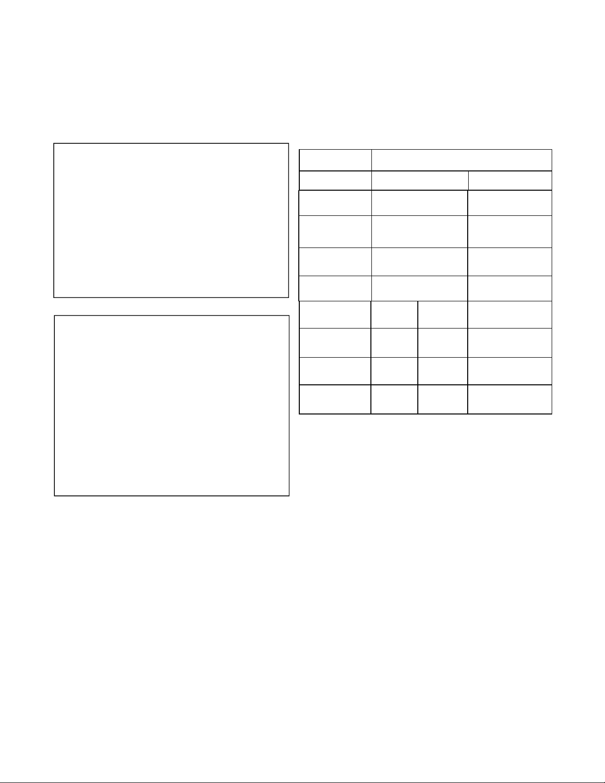
CabanaCoast® Firepit Series No.:
Model: 50”x32” Firepit
Type: Natural gas or Propane Gas
ORIFICE SIZE: NG = #31 LPG=# 43
Min. Gas supply for input Adj.
Max Inlet Supply Pressure
BTU input
CARBON MONOXIDE HAZARD
This appliance can produce carbon
monoxide which has no odor. Using it in
an enclosed space can kill you. Never use
this appliance in an enclosed space such
as a camper, tent, car or home.
LPG
11.0 In.w.c(2.7kpa)
14.0 In.w.c(3.5kpa)
63,000 Btu/hr
NG
7.0 In.w.c(1.7kpa)
14.0 In.w.c(3.5kpa)
55,000 Btu/hr
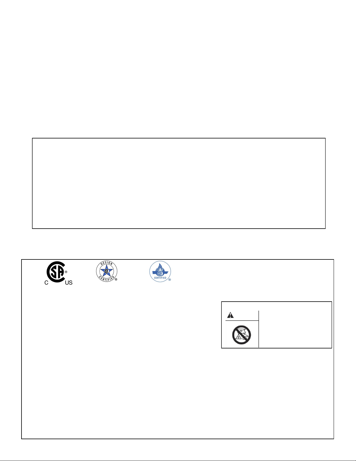
DANGER
WARNING
1.Must not be used for cooking
2.The current conguraon of the appliance is for LP gas.
3.For outdoor use only. If stored indoors, detach and leave cylinder outdoors.
4.An unconnected LP-cylinder should not be stored in the vicinity of this or any other appliance.
5.Keep a safe distance to avoid an explosion.
The instrucon manual contains important informaon necessary for the proper assembly and safe use of the appliance.
Read and follow all warnings and instrucons before assembling and using the appliance.
Follow all warnings and instrucon when using the appliance.
Minimum clearance:Top:6Ft.(72")sides:3.(36")
Minimum clearance from sides and back of unit to adjacent combusble construcon below top of unit,36 inches from sides 36 inches from
back. Distance from cylinder to the appliance should keep at least 8 inches.
WARNING: Improper installaon, adjustment, alteraon service or maintenance can cause injury or property damaged. Refer to the owners informaon manual provided
with this appliance. For assistance or addional informaon consult a qualied installer, service agency or the gas supplier.
2