CABASSE SANTORIN 30 I - User manual

SANTORIN
notice d’installation des caissons de graves
subwoofers operating instructions
subwoofers gebrauchsanweisung
30
www.cabasse.com
Cab no ice San orin30B.qxd:Cab no ice Sub-03.qxd 11/05/09 15:26 Page1

TSA 500 P
A4 A5 A6 A7
A1 A2 A3
1
fr a n ç a i s - e n g l i s h - d e u t s c h
Cab no ice San orin30B.qxd:Cab no ice Sub-03.qxd 11/05/09 15:26 Page2

fr a n ç a i s - e n g l i s h - d e u t s c h
TP1 TP2
TP3
TP4
TP5
TP6
RC1
RC3
RC2
RC4
RC5 RC6
2
3
a
écran LCD - LCD display - LCD-Anzeige
Cab no ice San orin30B.qxd:Cab no ice Sub-03.qxd 11/05/09 15:26 Page3

f r a n ç a i s - e n g l i s h - d e u t s c h
4
5
6
Cab no ice San orin30B.qxd:Cab no ice Sub-03.qxd 11/05/09 15:26 Page4

f r a n ç a i s
INSTRUCTIONS DE SECURITE
Explication des symboles -
L’éclair dans un triangle
équilatéral avertit de l’exis-
tence de tension élevée dangereu-
se non isolée à l’intérieur du cof-
fret du produit, d’une valeur suf-
fisante pour présenter un risque d’électrocution.
Le point d’exclamation dans un triangle équilatéral avertit de
l’existence d’instructions importantes quant à l’utilisation et
la maintenance dans la documentation jointe à ce produit.
Instructions -
Toutes les instructions de sécurité et d’utilisa-
tion doivent avoir été lues avant d’allumer tout appareil pour la
première fois.
etenez les instructions -
Elles doivent servir de référence
permanente pour tout ce qui suit.
Tenez compte des avertissements -
Les avertissements
présents sur le produit ou dans les notices d’utilisation doivent
être pris en compte.
Suivez les instructions -
Toutes les instructions d’utilisation
et de mise en œuvre doivent être scrupuleusement suivies.
Nettoyage -
Débranchez l’appareil avant tout nettoyage. N’uti-
lisez pas de solutions nettoyantes sous forme liquide ou en aéro-
sols. Employez de préférence un chiffon humide.
Accessoires -
N’utilisez pas d’accessoires qui ne soient pas expli-
citement recommandés par le constructeur, sous peine de risquer
divers accidents.
Eau et humidité -
L’appareil ne doit pas être utilisé près de
l’eau, par exemple à proximité d’une baignoire, d’un évier, dans
un sous-sol humide, près d’une piscine, ou de tout ce qui y res-
semble de près ou de loin.
Chariots et supports - La manutention doit être
effectuée seulement avec des chariots et supports agréés
par le fabricant.
> Attention aux chariots de manutention
Installation sur mobiliers et supports -
Ne placez pas
cet appareil sur un support instable, qu’il s’agisse de pieds, tré-
pieds, tables, étagères, etc. Il pourrait tomber et causer des bles-
sures sérieuses à un enfant ou un adulte qui se trouverait à proxi-
mité.
Ventilations -
L’appareil doit être positionné de telle sorte
qu’il ne gêne pas sa propre ventilation. Par exemple, il ne doit pas
être installé sur un lit, un canapé, une couverture ou des surfaces
similaires qui pourraient bloquer ses orifices d’aération. Il ne
doit pas non plus être encastré dans des enceintes confinées
comme des étagères étroites ou des meubles qui pourraient
limiter la quantité d’air disponible aux entrées d’air.
Alimentation -
L’appareil ne doit être relié qu’à une source élec-
trique du type écrit dans le mode d’emploi ou conforme à la
sérigraphie sur le produit. Si vous n’êtes pas sûr du type de cou-
rant fourni à l’endroit où vous vous trouvez, adressez-vous à
votre revendeur ou à la compagnie électrique locale.
Sacs plastiques -
Ne pas laisser les sacs plastiques de l’em-
ballage à portée des enfants afin d’éviter tout risque d’étouffe-
ment.
Protection des câbles d’alimentation -
Le cheminement
des câbles d’alimentation doit être prévu de telle sorte qu’ils ne
puissent pas être piétinés, pincés, coincés par d’autres appa-
reils posés dessus, et une attention toute particulière doit être
accordée à l’adéquation des prises et à la liaison du cordon
avec l’appareil.
Foudre -
Pour une meilleure protection de l’appareil pendant
les orages ou s’il doit rester inutilisé pendant une longue pério-
de, débranchez le cordon d’alimentation et débranchez la prise
d’antenne, vous éviterez ainsi les risques de détérioration dus à
la foudre ou aux surtensions.
Surcharges électriques -
Ne surchargez pas les prises d’ali-
mentation, les prolongateurs ou les rappels d’alimentation. Il
pourrait en résulter incendies ou électrocutions.
Corps et liquides étrangers -
On doit être attentif à ne
jamais laisser entrer d’éléments ou de liquides étrangers dans l’ap-
pareil. Ils pourraient occasionner incendies ou électrocutions. Ne
versez jamais aucun liquide d’aucune sorte sur l’appareil.
Entretien -
L’utilisateur ne doit pas tenter de s’occuper des opé-
rations de maintenance au-delà de celles décrites dans le mode
d’emploi. Tout ce qui dépasse le simple niveau de l’entretien
doit être effectué par un personnel qualifié.
Maintenance -
Dans les cas suivants, vous devez impérative-
ment débrancher votre appareil et le faire vérifier par un technicien
qualifié :
■l’alimentation ou la prise a été endommagée.
■des corps étrangers ou du liquide se sont introduits dans l’ap-
pareil.
■l’appareil a été exposé à la pluie ou a été aspergé d’eau.
■l’appareil ne semble pas marcher correctement alors que vous
l’utilisez dans le cadre de ses instructions de fonctionnement
normal. Ne manipulez que les contrôles couverts par le mode
d’emploi. Toute autre procédure pourrait le détériorer et néces-
siter l’intervention d’un technicien qualifié.
■l’appareil est tombé ou bien sa carrosserie est endommagée.
■l’appareil affiche des performances nettement modifiées.
Pièces détachées -
Si la réparation a nécessité l’utilisation de
pièces détachées, assurez-vous que le technicien a bien utilisé les
références préconisées par le fabricant ou présentant les mêmes
caractéristiques que les pièces originales. Des pièces non
conformes peuvent provoquer incendies, électrocutions ou
autres.
Vérifications -
Après toute intervention sur l’appareil, deman-
dez au technicien d’effectuer des tests afin de garantir que l’ap-
pareil fonctionne en toute sécurité.
Exposition aux fortes températures -
L’appareil doit être
tenu éloigné de sources de chaleur comme radiateurs, chauf-
fage divers, amplificateurs, ou tous autres éléments susceptibles
de le placer dans des conditions de températures anormale-
ment élevées.
Vous venez d’acheter des enceintes Cabasse et nous vous remercions de votre confiance.
Avant de commencer l’installation de votre système, nous vous recommandons de lire cette notice
attentivement et intégralement.
Attention !
pour éviter les chocs électriques, introduire la lame
la plus large de la fiche dans la borne correspondante et pousser
jusqu’au fond
Valable aux USA, au Canada et autres pays concernés
Cab no ice San orin30B.qxd:Cab no ice Sub-03.qxd 11/05/09 15:26 Page5

f r a n ç a i s
DEBALLAGE DU SANTORIN 30
Le système est livré dans 2 emballages.
Contenu du carton principal: un Santorin 30, 4 cônes de découplage, un
câble secteur, 1 fiche de garantie et un manuel d'utilisation.
Contenu du carton "kit microphone": un préamplificateur-micro et son
alimentation, 1 microphone et son pied, 2 câbles de liaison XLR.
Ouvrir le côté mentionné "Côté à ouvrir" du carton principal contenant
le Santorin 30, replier sur les cotés les rabats supérieurs du carton. Retour-
ner l’emballage avec son contenu, vider le carton de son contenu et sor-
tir l’enceinte de son emballage. Nous vous conseillons de conserver les
emballages à plat pour une utilisation ultérieure éventuelle.
POSITIONNEMENT ET PLACEMENT
DES ENCEINTES ACOUSTIQUES
Positionnement des enceintes
Nos caissons de graves sont prévus pour fonctionner en position
verticale.
La plupart de nos modèles sont livrés avec un jeu de pointes ou cônes
de découplage. Ces accessoires sont à visser dans l’empla cement pré-
vu sous vos enceintes. Ces pointes ou cônes de découplage permettent
d’assurer une meilleure stabilité de l’enceinte tout en limitant les réso-
nances pouvant être générées par certains types de sols comme les plan-
chers par exemple.
Le champ magnétique des moteurs des haut-parleurs va rayonner au delà
de l’enveloppe de l’enceinte acoustique. Il faut donc éloigner d’environ
50 cm les appareils et objets sensibles à ce type de rayonnement (télé-
viseurs et écrans d'ordinateur type CRT, disquettes informatiques,
bandes magnétiques audio ou vidéo, cartes à puces...).
Le placement optimal
pour une écoute stéréo en 2.1
Dans le cadre d’une écoute stéréo avec 2 enceintes ou 2 satellites et 1
caisson de graves, nous vous conseillons de placer le caisson de graves
dans la zone écoute avant. Le placement du caisson contre un mur ren-
force l’extrême grave et limite les réflexions de 80 à 200Hz. Cependant,
pour obtenir le meilleur résultat, il est toujours nécessaire de faire des essais
d’emplacement en fonction de l’acoustique de la pièce.
Le placement optimal
pour une écoute Home Cinéma ou 5.1
Pour la disposition d’un ensemble home cinéma, il est important
d’apporter la plus grande attention à la disposition des enceintes
supplémentaires spécifiques.
■L’enceinte centrale doit être placée le plus près possible de l’écran en
recherchant la position dans le lieu d’écoute qui apporte la plus
grande cohésion sur les dialogues entre le son et I’image. En pratique,
cela revient à placer l’enceinte centrale au-dessus de l’écran si les enceintes
principales sont plus basses que celui-ci, et en dessous si les enceintes
principales sont plus hautes.
■Les enceintes arrière, voies d’effet ou surround doivent être disposées
contre les murs latéraux, légèrement en hauteur. Elles doivent être situées
légèrement en arrière de la zone d’écoute.
■Le caisson de graves doit être placé dans la zone d’écoute avant. Son
placement contre un mur renforce l’extrême grave et limite les réflexions
de 80 à 200 Hz. Cependant, pour obtenir le meilleur résultat, il est
toujours nécessaire de faire des essais d’emplacement en fonction de
l’acoustique de la pièce.
Votre amplificateur audio-vidéo permet le réglage des niveaux et des
distances de chaque enceinte. Ce réglage doit être ajusté avec soin de
manière à obtenir une parfaite cohésion entre les sources sonores.
Il est nécessaire d’éteindre tous les appareils avant la connexion des
enceintes. Pour le branchement de vos enceintes acoustiques, il faut
tenir compte de la section des câbles et du respect des phases.
Section des câbles
Pour conserver toutes les qualités
des enceintes acoustiques et éviter
les pertes de puissance, il faut que
la résistance électrique des câbles de
branchement entre I’enceinte et
I’amplificateur soit la plus faible
possible. Pour vous aider à choisir
la meilleure section de câble pour
votre installation, veuillez suivre le tableau récapitulatif.
Phase
Les enceintes et les amplificateurs ont leurs bornes de branchement
repérées. Il y a deux façons courantes d’effectuer ce repère : soit une
borne rouge ou repère +, soit une borne noire ou repère -.
Dans tous les cas, il faut que les deux canaux soient branchés de façon
identique, c’est à dire par exemple que la borne rouge ou+ de l’encein-
te aille à la borne rouge ou+ de l’amplificateur ; la borne noire ou de
I’enceinte ira dans ce cas à la borne noire ou- de I’amplificateur.
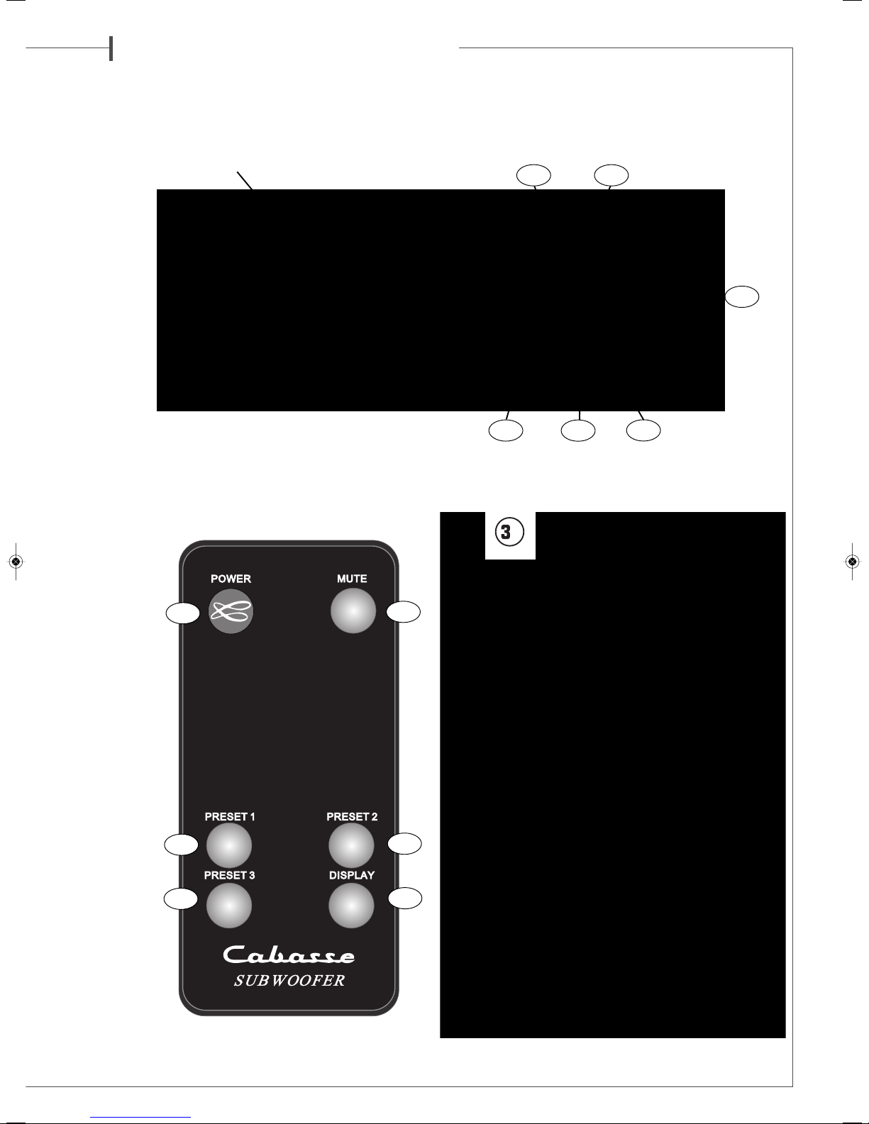
Secteur et mise en route
La prise sert à alimenter le caisson de
graves. La sélection de la tension
d’alimentation est effectuée par le
commutateur 115 V - 230 V . La mise
en route s’effectue par l’interrupteur
POWER , en le mettant dans la
position ON.
Mettre le subwoofer en mode actif en
appuyant sur la touche POWER de la
télécommande ou sur n'importe quelle
touche du clavier frontal de caisson de graves.
3 à 4 secondes sont nécessaires à l'activation du système..
RÉGLAGES
I) DESC IPTIF DES PA AMET ES EGLABLES
UTILISATION DU CLAVIER DU PANNEAU DE CONTROLE RONTAL :
Les 5 touches du panneau de contrôle permettent de se déplacer dans
le menu déroulant du Santorin 30.
Les touches « ←» et « →» (TP6 et TP3) permettent de sélectionner les
paramètres ci-dessous, les touches « ↓» et « ↑» (TP4 et TP2) de
choisir parmi les options ou de sélectionner la bonne valeur. La touche
« ENTER » (TP1) permet de confirmer un réglage en réponse aux
demandes « ENTER ? » et « VALIDATE ? ».
A) PARA ETRES REGLABLES UNIQUE ENT A PARTIR DU
PANNEAU DE CONTROLE :
- SOURCE : sélection des types d’entrées/sorties utilisées :
■RCA+HL : entrées RCA « LOW LEVEL INPUTS» et
entrées/sorties haut-niveau « HIGH LEVEL INPUTS »
(bornes haut-parleur ). Il est possible suivant les configurations
système d’utiliser simultanément les entrées RCA et HL.
■XLR : connecteurs XLR
- CHANNELS : sélection des canaux d’entrée utilisés :
■R : canal droit
■L : canal gauche
■R+L : canaux droit et gauche
- VOLUME : réglage du niveau sonore du caisson de -30 dB à +6 dB. Les
A3
A1
A2
A7
A5
A6
Distance Section
ampli - enceinte
4,5 m 1,5 mm2
6 m 2 mm2
7,5 m 2,5 mm2
9 m 3 mm2
12 m 4 mm2
Attention !
Avant tout branchement,
s’assurer que votre tension
secteur correspond bien à
la tension secteur sélectionnée
sur le commutateur
115 V - 230 V .
A1
Attention ! Etant donné le poids élevé de cette enceinte,
2 personnes sont nécessaires pour effectuer le déballage.
Cab no ice San orin30B.qxd:Cab no ice Sub-03.qxd 11/05/09 15:26 Page6

f r a n ç a i s
touches « « + » et « - » permettent le réglage du niveau par pas de 1 dB.
- LOW PASS ILTER = REQUENCY : réglage de la fréquence de coupure
haute du Santorin entre 30 Hz et 200 Hz. Les touches « - » et « + »
permettent de choisir cette fréquence par pas de 1 Hz.
- PHASE : réglage de la phase de 0° à 180°. Les touches « - » et « + »
permettent de régler la mise en phase du Santorin avec les enceintes
principales par pas de 1 degré.
- PARAMETRIC 1 – PARAMETRIC 2 – PARAMETRIC 3 : ces 3 modules
paramétriques permettent d’effectuer des corrections pour adapter la
courbe de réponse du Santorin aux éventuels défauts acoustiques de la
pièce. Ils sont mis en service soit manuellement soit via la fonction
d’adaptation automatique.
- ADAPTATION AUTOMATIQUE (AUTO ACQUISITION) : à utiliser
après avoir connecté le microphone et le préamplificateur micro livré avec
le Santorin pour un réglage automatique des 3 modules paramétriques.
Il est possible d’affiner manuellement les corrections automatiques
en agissant sur les paramètres suivants en mode manuel via les
menus « PARAMETRIC 1 – PARAMETRIC 2 – PARAMETRIC 3 » :
■CENTER : point milieu de la correction, sélectionnable de 30 à
200 Hz par pas de 1 Hz
■BAND WIDTH : étendue de la correction de part et d’autre du
point milieu, ajustable d’1/8ème d’octave à 2 octaves en pas
d’1/8ème d’octave.
■GAIN : intensité de la correction, ajustable de -12 dB à +4 dB
par pas de 1 dB
- POWER : Gestion de l’alimentation
■ON : le Santorin est opérationnel : la remise en route s’effectue
soit en appuyant sur la touche « POWER » de la télécommande soit
en appuyant sur une des 5 touches du panneau de contrôle.
■O : arrêt du Santorin
■AUTO : gestion automatique du ON/O du Santorin en fonction
de l’utilisation et de la non utilisation de votre système audio, avec mise
en veille automatique après 20 minutes sans signal audio.. onction
conseillée : une fois que les réglages du Santorin sont réalisés, il n’est
alors plus nécessaire d’utiliser la télécommande et/ou le panneau de
contrôle.
- DELAY : réglage de la distance de 0 à 6,8 mètres par pas de 0,34 mètre.
B) PARA ETRES REGLABLES A PARTIR DE PANNEAU DE CONTRO-
LE ET DE LA TELECO ANDE
- POWER : mise en route du Santorin
- MUTE : coupure du signal
■MUTE ON : le signal sonore est coupé mais l’amplificateur est
sous-tension et tous les réglages sont accessibles.
■MUTE O : le caisson est opérationnel
- PRESET 1, PRESET 2, PRESET 3: appel des 3 préréglages si ceux-ci
ont été programmés par l’utilisateur.
- DISPLAY : affichage à l’écran. Une simple pression sur cette touche éteint
ou allume l’éclairage de l’écran LCD
CLAVIE DE LA TELECOMMANDE :
- POWER (RC1) : mise en route du Santorin
- MUTE (RC2) : coupure du signal
■MUTE ON : le signal sonore est coupé mais l’amplificateur est
sous-tension et tous les réglages sont accessibles.
■MUTE O : le caisson est opérationnel
- PRESET 1, PRESET 2, PRESET 3 (RC3, RC4, RC5) : appel des 3
préréglages si ceux-ci ont été programmés par l’utilisateur.
- DISPLAY (RC6): affichage à l’écran. Une simple pression sur cette
touche éteint ou allume l’éclairage de l’écran LCD.
II) P OCEDU ES DE B ANCHEMENTS ET DE CONFI-
GU ATION SYSTEME
L’électronique du Santorin a été conçue pour une utilisation optimum
dans pratiquement toutes les configurations audio et vidéo possibles. Pour
une utilisation domestique, voici la procédure pour les 2 configurations
principales:
A) CONFIGURATION 2.1 : 2 satellites + 1 Santorin reliés à un ampli-
ficateur stéréo
a)Connecter les entrées droites (R) et gauches (L) HI LEVEL INPUT
du Santorin aux bornes de sortie haut-parleur droites et gauches de votre
amplificateur avec du câble haut-parleur. Bien respecter les polarités
en reliant les bornes + (rouges) du Santorin à celles de l’amplificateur
b) Connecter les sorties droites (R) et gauches (L) HI LEVEL
OUTPUT du Santorin aux bornes des 2 satellites. Bien respecter
les polarités en reliant les bornes + (rouges) du Santorin à celles des
enceintes satellites.
c)Connecter le Santorin 30 au secteur et l’activer
d)Configurer les rubriques « SOURCE » et « CHANNELS » dans le
menu du Santorin :
■SOURCE = RCA + HL
■CHANNELS = R+L
B) CONFIGURATION 5.1: 5 enceintes + 1 Santorin reliés à un
amplificateur audio-vidéo
a)Connecter l’entrée droite (R) ou gauche (L) LOW LEVEL INPUT
du Santorin à la borne de sortie SUBWOO ER / L E de votre
amplificateur AV avec un câble de liaison RCA-RCA. Si l’amplifica-
teur ou le préamplificateur audiovidéo est également équipé d’une
sortie symétrique XLR, nous conseillons de choisir cette solution et
d'utiliser une des entrées .
b)Connecter le Santorin 30 au secteur et l’activer
c)Configurer les rubriques « SOURCE » et « CHANNELS » dans le
menu du Santorin :
■SOURCE = RCA + HL ou XLR suivant l’entrée choisie
■CHANNELS = R ou L, suivant l’entrée choisie
III) P OCEDU ES DE EGLAGE DU SANTO IN
Après avoir effectué toutes les connections comme indiqué plus haut et
branché le Santorin sur le secteur, mettre le caisson de grave en mode
« ON » soit en appuyant sur la touche « POWER » de la télécomman-
de soit sur une des 5 touches du panneau de contrôle. Procéder
ensuite aux réglages ci-dessous en navigant dans le menu du panneau
de contrôle détaillé ci-dessus.
A) SELECTION DE LA SOURCE : vérifier dans la rubrique « SOURCE
» les types d’entrées/sorties utilisées pour la connexion du Santorin
avec le préampli ou amplificateur en amont :
■RCA+HL : entrées RCA et entrées/sorties haut-niveau
(bornes haut-parleur)
■XLR : connecteurs XLR
A5
A4
A7
A6
Attention ! Un ronflement est susceptible d'apparaître avec ce type
de configuration, suivant l’amplificateur utilisé. Pour supprimer cette
gène, il suffit de relier la masse électrique du Santorin 30 à la masse
électrique de la source audio avec un câble RCA-RCA (non fourni)
entre une des entrées RCA du Santorin 30 et une des entrées RCA
non utilisées de la source audio
Cab no ice San orin30B.qxd:Cab no ice Sub-03.qxd 11/05/09 15:26 Page7

f r a n ç a i s
B) SELECTION DES CANAUX D’ENTREE : vérifier dans la rubrique
« CHANNELS » les canaux d’entrée utilisés :
a. R : canal droit
b. L : canal gauche
c. R+L : canaux droit et gauche
C) REGLAGE DE LA DISTANCE: pour optimiser la cohérence du
système, si le Santorin est plus proche du point d’écoute que ne le
sont les enceintes principales gauche et droite, entrer dans la rubrique
« DELAY » la distance qui sépare les enceintes principales du caisson par
rapport au point d’écoute. Il faut pour cela mesurer le rayon du cercle
dont le centre est le point d’écoute et le périmètre passe par le tweeter
de chaque enceinte principale. La valeur à entrer dans le menu est la
différence entre ce rayon et la distance qui sépare le Santorin du point
d’écoute (voir croquis )
D) DETER INATION DE LA FREQUENCE DE COUPURE
HAUTE DU SANTORIN (LOW PASS FILTER)
Elle est fonction du type d’utilisation du caisson et des possibilités de
réglages intégrées au processeur de l’amplificateur AV associé :
a) Utilisation en 5.1, 6.1, 7.1 pour la seule reproduction du canal
d’effets de graves (L E) en complément d’enceintes large bande
Ce canal d’effet de grave est géré par le processeur de l’amplificateur
AV, il convient donc de régler la fréquence de coupure haute du Santorin
sur 200 Hz pour éviter d’éventuels chevauchements de filtrages.
b) Utilisation en 5.1, 6.1, 7.1 avec des enceintes (dites satellites) néces-
sitant un caisson de graves : régler la fréquence de coupure haute du
Santorin sur 200 Hz et ajuster la fréquence de coupure basse des
enceintes satellites dans le menu SET-UP de l’amplificateur audio-video
au plus près des caractéristiques données pour ces satellites. Il faut
généralement commencer par indiquer dans le « SPEAKER SET-UP » ou
équivalent que ces enceintes doivent fonctionner en mode « SMALL ».
il faudra ensuite choisir la fréquence charnière entre les enceintes et le
caisson. Pour les enceintes Cabasse, choisir la position de réglage la
plus proche des valeurs listées dans le tableau ci-dessous :
Utilisation en mode 2.1: régler la fréquence de coupure haute du
subwoofer en fonction de la coupure basse des enceintes Cabasse
asociées. Les valeurs à enregistrer dans le menu du Santorin 30 figurent
dans l'encadré ci-dessus, elles sont également disponibles pour d'autres
modèles sur nos fiches techniques ainsi que sur www.cabasse.com
Un installateur expérimenté pourra notamment par des mesures
acoustiques choisir en fonction de l’environnement acoustique des
fréquences de coupure différentes de celles déterminées par nos mesures
en chambre sourde.
Dans le cas d’association de satellites à fréquence de coupures basses
différentes dans une configuration à 3 canaux et plus, la fréquence de
coupure haute à enregistrer dans le processeur sera la plus élevée.
E)REGLAGE DU VOLU E : dans le cas d’utilisation du Santorin avec
des enceintes dites satellites nous recommandons d’ajuster le volume
en utilisant en mode stéréo une pièce musicale connue et riche en
graves. Une fois ce réglage établi, dans le cas d’une configuration en
multi canal, l’ajustement du volume des effets de graves (L E) sera
effectué via le menu SET UP de l’amplificateur AV.
F) REGLAGE DE LA PHASE : il permet si nécessaire d’aplatir la
courbe de réponse à la fréquence charnière entre le Santorin et les
enceintes principales. Une fois les réglages ci-dessus effectués, il
faut déterminer l’angle de phasage auquel le niveau perçu des
graves est le plus élevé, en comparant différents réglages en mode
stéréo une pièce musicale connue et riche en graves.
Noter qu'à distances égales par rapport au point d'écoute ce
réglage de phase doit théoriquement être à 0° pour iO2, Riga et
Baltic Evolution. Il est souvent nécessaire de réajuster le réglage de
phase après toute modification de la fréquence de coupure et/ou du
positionnement du Santorin.
G) UTILISATION DES ODULES DE FILTRAGE PARA ETRIQUES :
fort de son expérience dans le traitement numérique du signal,
Cabasse a développé pour le Santorin 30 des modules de corrections
de l’acoustique des salles très sophistiqués. Quand un filtre graphique
ne permet que d’ajuster le volume sur une bande de fréquence fixe, un
filtre paramétrique permet un réglage plus fin et naturel car parfaitement
positionné sur la zone critique, le centre de la correction et son étendue
en fréquence étant ajustable. Un seul filtre paramétrique peut suffire alors
qu’un système graphique implique dans tous les cas l’activation de
l’ensemble des filtres sur toute la bande passante du caisson de graves,
occasionnant de nombreux phénomènes de déphasage.
G1) EQUILIBRAGE AUTO ATIQUE DE LA RÉPONSE EN
FRÉQUENCE
1) Assurez-vous que tous les réglages ci-dessus sont bien réalisés
2) Sélectionner la position « PRESET 2 » pour le premier équilibrage,
afin de garder la position « PRESET 1 » en référence.
3) Déballer les accessoires de mesure fournis avec le Santorin 30 :
1 micro de mesure, un préamplificateur micro, un câble XLR-XLR
pour microphone, un câble de liaison XLR-XLR préamplificateur-sub-
woofer.
4) Positionner le micro de mesures à la position d'écoute (P1), le
connecter au préampli micro avec le câble XLR-XLR à l’entrée XLR
micro « INPUT ».
5) Connecter le préampli micro au Santorin en reliant sa sortie XLR
« OUTPUT » à l’entrée XLR « RIGHT » .
6)Sur le préamplificateur micro, régler le gain « GAIN » sur la valeur
centrale, le volume de sortie « OUTPUT » sur la valeur centrale,
enfoncer la touche +48 V puis connecter le préamplificateur au
secteur grâce à son alimentation externe.
7) Dans le menu du Santorin 30 :
a. sélectionner « RCA+HL » dans la rubrique « SOURCE » : ce mode
permet d’éviter des possibles effets Larsen (sifflements)
b. « CHANNELS »+ « VOLUME » : l’entrée XLR droite est automati-
quement sélectionnée comme entrée micro et gère automatiquement
le volume
c. Dans la rubrique «AUTO ACQUISITION » confirmer le lancement
des mesures avec la touche « ENTER »
d. « Start Acq. 1 ? » :
d1.positionner le micro au centre de la zone d’écoute à la
hauteur moyenne d’écoute (P1) sur le schéma (6)
d2. valider par la touche « ENTER » le premier train de mesures
4
65
A5
- ormentera : 80 Hz
- Minorca: 60 Hz
- aro: 50 Hz
- Riva: 45 Hz
- iO2 : 125 Hz
- Ki: 100 Hz
- Linea: 80 Hz
- Riga: 80 Hz
- Baltic Evolution : 65 Hz
Attention
Si l'écran du panneau de contrôle affiche le message "No signal
input", vérifiez les branchements et réglages du préamplificateur
et du microphone indiqués ci-dessus et recommencer la procédure
Cab no ice San orin30B.qxd:Cab no ice Sub-03.qxd 11/05/09 15:26 Page8

f r a n ç a i s
e. « Start Acq. 2 ? » :
e1.positionner le micro à environ 1 m à droite ou a gauche de P1
(optez pour la position la plus éloignée des murs de la pièce) et à
une hauteur d’environ 1,50 m (P2)
e2.valider par la touche « ENTER » le second train de mesures
f. « Start Acq. 3 ? » :
f1.positionner le micro à environ 60 cm de P1, à 45° de la ligne
P1-P2, P1 devant se trouver entre P2 et P3.
Hauteur micro = 1,20 m environ
f2.valider par la touche « ENTER » le troisième train de mesures
g. « INISHED ! » L'équilibrage automatique pour le PRESET choisi
est terminé. Valider la fin de l’équilibrage en appuyant sur la touche
« OK ». Il est alors possible de faire un nouvel équilibrage avec des posi-
tions de micro différentes et de l’enregistrer dans un PRESET différent
pour effectuer des comparaisons auditives.
G2) EQUILIBRAGE ANUEL DE LA RÉPONSE EN FRÉQUENCE
Ce mode de réglage nécessite une grande expérience et du matériel de
mesure adapté pour parvenir à être plus efficace que l’équilibrage
automatique. Il peut cependant être utilisé après un équilibrage
automatique pour tester à l’écoute des réglages avec des valeurs
légèrement différentes et/ou enregistrer en PRESET (touches RC6) des
variantes à utiliser suivant le type d’écoute ou de source.
1) Sélectionner le PRESET
2) Sélectionner avec les touches « ←» et « →» (TP6 et TP3) puis
« ENTER » du panneau de contrôle un des 3 modules paramétriques
: PARAMETRIC 1, PARAMETRIC 2, PARAMETRIC 3.
3) « CENTER » : Déterminer la fréquence centrale de la bande de fré-
quence à corriger (valeur exprimée en Hz)
4) « BAND » : Choisissez la largeur de la bande de fréquence pour la
correction paramétrique (valeur exprimée en fraction d’octave,
d’1/8ème à 2 octaves.
5) « GAIN » : Régler la valeur de la correction entre -12 dB et +4 dB.
6) Valider les 3 réglages du module en passant en validant «EXIT » par
la touche ENTER (TP1)
H) UTILISATION DES « PRESET »:
Le Santorin 30 est livré en configuration PRESET 1. Le gain des 3
modules paramétriques est alors sur la position O dB et la largeur de
bande sur 1 Octave. Les fréquences sont préréglées sur 50 Hz pour PARA
1, 60 Hz pour PARA 2, 70 Hz pour PARA 3.
1) enregistrement des « PRESET » : il est automatique,
toute modification de valeur sur un ou plusieurs PARA
est automatiquement enregistrée sur le PRESET sélectionné.
2) appel des « PRESET » :
- Avec la télécommande via les touches d’accès direct PRESET1,
PRESET2, PRESET 3
- Avec le menu déroulant du panneau de contrôle en sélectionnant
le sous-menu « PRESET » avec les touches « ←» et « →» (TP6 et TP3)
puis PRESET1, PRESET2, PRESET 3 avec les touches « ↓» et « ↑» (TP4
et TP2)
I) INTENSITE DE L’AFFICHAGE
La touche « DISPLAY » de la télécommande permet de supprimer le
rétro-éclairage de l’écran LCD du panneau de contrôle. Il suffit de
presser sur cette touche pour activer ou supprimer cette fonction.
SPECIFICATIONS &
CARACTERISTIQUES TECHNIQUES
Santorin 30
Caisson de graves actif
Haut-parleur : 30 cm ø - modèle 30ND40
Bande passante : 22-200 Hz en local semi-réverbérant
Pression impulsionnelle maximale : 111 dB RMS
Puissance nominale de l’ampli : 500 W RMS
Puissance crête : 1000 W
Fréquence de coupure : réglable de 30 à 200 Hz par pas de 1Hz
églage de phase : de 0° à 180° par pas de 1°
Alimentation : 115 / 230 V AC - 50 / 60 Hz
Consommation maximum : 625 W
Dimensions (h x l x p) : 43 x 36 x 38 cm
Poids : 28 kg
Température d'utilisation : +5°C à +35°C
Température de stockage : -5°C to +40°C
Taux d'humidité en utilisation : 40% to 70%
Etant donné l’évolution des techniques mises en oeuvre pour une fia-
bilité accrue et une recherche constante de qualité optimale, Cabas-
se se réserve le droit d’apporter toutes modifications aux modèles
présentés sur les fiches techniques ou les documents publicitaires.
emplacement de la pile de la télécommande: retourner la télé-
commande, coté face vers le sol, pincer le verrou et tirer le porte-pile
en bas de télécommande (figure 3a). Enlever la pile usagée et la rem-
placer par une autre pile lithium 3V type CR2025. Mettre la pile usa-
gée au rebut suivant les informations ci-dessous.
informations sur les piles et accumulateurs présents dans l’équipe-
ment (Applicable dans les pays de l’Union européenne)
Ce symbole, représentant une poubelle sur roues
barrée d’une croix, apposée sur une pile ou un
accumulateur, indique que cette pile ou accu-
mulateur ne doit pas être éliminé comme un
déchet ménager non trié mais qu’il doit être col-
lecté de manière séparée de sorte d’en faciliter le
traitement et le recyclage.
Il doit être remis à un point de collecte pour le traitement des piles et
accumulateurs usagés. En s’assurant que ce produit est bien mis au
rebut de manière appropriée, vous aiderez à prévenir les conséquences
négatives potentielles pour l’environnement et la santé humaine. Le recy-
clage des matériaux aidera à conserver les ressources naturelles. Pour
toute information supplémentaire au sujet du recyclage de ce pro-
duit, vous pouvez contacter votre municipalité, votre déchetterie ou
le magasin ou vous avez acheté le produit.
Traitement des appareils électriques et électroniques en fin de vie
(Applicable dans les pays de l’Union Européenne )
Ce symbole, représentant une poubelle sur roues barrée d’une croix,
apposé sur le produit, indique que ce produit ne doit pas être traité
avec les déchets ménagers. Il doit être remis à un point de collecte pour
le traitement des équipements électriques et électroniques en fin de vie.
En s’assurant que ce produit est bien mis au rebut de manière appro-
priée, vous aiderez à prévenir les conséquences négatives potentielles
pour l’environnement et la santé humaine. Le recyclage des maté-
riaux aidera à conserver les ressources naturelles. Pour toute infor-
mation supplémentaire au sujet du recyclage de ce produit, vous pou-
vez contacter votre municipalité, votre déchèterie ou le magasin où vous
avez acheté le produit.
Cab no ice San orin30B.qxd:Cab no ice Sub-03.qxd 11/05/09 15:26 Page9

en g l i s h
SAFETY INSTRUCTIONS
Explanation of graphical sym-
bols -
The lightning flash with
arrowhead symbol, within an
equilateral triangle, is inten-
ded to alert you to the presence of
uninsulated “dangerous voltage”
within the product’s enclosure that may be of sufficient magnitu-
de to constitute a risk of electric shock to persons.
The exclamation point within an equilateral triangle is intended
to alert you to the presence of important operating and
maintenance (servicing) instructions in the literature accom-
panying the appliance.
Instructions -
Carefully read through all the safety and oper-
ating instructions before switching on any device for the first
time.
Keep these instructions in mind -
They will be constant-
ly referred to through this manual.
Pay special care to warnings -
All the warning labels on the
product or warning notes in the user’s manual must be followed.
Follow the instructions -
ollow carefully all the installation
and operation instructions.
Cleaning -
Always remove the power cord before cleaning the
device. Do not use cleaning solvent, whether liquid or air spray.
Using a soft damp cloth is recommended.
Accessories -
To avoid incidents, only use accessories express-
ly recommended by Cabasse.
Water and moisture -
The product shall not be used in
damp or wet locations, such as humid basements, next to a bath-
tub, sink, swimming pool or any other similar conditions.
Carts and Stands - The appliance should be used
only with a cart or stand that is recommended by the
manufacturer.
> Portable cart warning
Installation on a piece of furniture and stands -
Do not
place this device on an unsteady surface, i.e. a stand, tripod,
table, shelf, etc. It may fall and cause serious injury to a nearby
child or adult.
Ventilation outlets -
The device shall not be placed in a posi-
tion that restrains the operation of its fans. Avoid installing the
device on a bed, couch, blanket or other similar surfaces that
may prevent the appropriate air flow. Do not install the device in
a confined space, such as a book shelf or other piece of furniture,
that could prevent sufficient air from flowing freely.
Power -
The device shall only be connected to a source of pow-
er compliant to the one described in this manual or on relevant
printed labels on the product. If you are not sure of the type of
power available, please contact your reseller or the local power
company.
Power cords -
The power cords must be laid out in such a way
that they cannot be walked on, pinched, bent under
other devices. Also pay special attention to the matching of the
plugs and the connection of the cord to the device.
Plastic bags -
Keep them away from children to prevent any
risk of suffocation.
Lightning -
or better protection against lightning or if the
device must remain unused for long stretches of time, unplug
the power cord and antenna jack. This minimises potential dam-
ages due to lightning or line surges.
Overloads -
Avoid overloading the power plugs, extension
cords or power relays. This could result in fire or electric shocks.
Foreign bodies and liquids -
Avoid letting foreign materi-
als or liquids enter the device. They could cause fire or electric
shocks. Never spill any liquid on the device.
Maintenance -
Users must never attempt to maintain the
device on their own, except for those maintenance operations
described in this manual. Any task beyond regular user mainte-
nance must be performed by qualified service operators.
Troubleshooting -
You must unplug your device from the
power supply and have it checked by a qualified technician if:
■The power supply or the plug is damaged.
■oreign bodies or liquid penetrated the device.
■The device was exposed to dripping or splashing.
■The device does not seem to work correctly under normal oper-
ating conditions. Only operate the controls described in this
manual. Any other operation could damage the device and require
on-site visit of a qualified technician.
■The device has fallen or its housing is damaged.
■The performances of the device are strongly altered.
Spare parts -
If spare parts are needed to repair the device,
make sure that the technician followed the manufacturer’s rec-
ommendations or that the replacing parts feature the same spec-
ifications as the original ones. Non-compliant parts can result in
multiple damages, including fire or electric shocks.
Checks -
After any servicing of the device, ask the technician to
perform appropriate testing to make sure that the device works
safely.
Exposure to high temperatures -
The device should be kept
away from heating sources, such as radiators, heaters, ampli-
fiers or any other similar item likely to make the operating tem-
perature rise excessively.
UNPACKING
The system is delivered in 2 cartons.
The larger packing includes one Santorin 30 subwoofer, a set of 4
decoupling cones, a power cable, the guarantee card and the owner's
manual.
The smaller packing contains a measurement microphone, a tabletop
microphone stand, a microphone amplifier with its power supply ,
2 XLR-XLR cables.
After opening the carton flaps of the main packing, fold them right
back and invert the carton contents.
After opening the top carton flaps, remove the grille. Then fold the car-
ton flaps right back and invert the carton contents.
Lift the carton clear of the contents and remove the inner packaging
from the speakers. We suggest you to retain the packing for future use.
hank you very much for choosing Cabasse speakers.
Please read these instructions carefully before setting up your speakers.
Caution ! o prevent electric shock, match wide blade plug to wide
slot, insert fully.
Applicable for USA, Canada or where approved for usage
Cab no ice San orin30B.qxd:Cab no ice Sub-03.qxd 11/05/09 15:26 Page10

e n g l i s h
POSITIONING
Speakers positioning
Our speakers have been designed to function in a vertical position.
The majority of our models are delivered with a set of decoupling
spikes or cones, these accessories are to be screwed in the inserts
under the cabinets. These accessories ensure the stability of the
speaker while limiting resonance coming from certain types of
grounds like wood floors.
Powerful drivers generate magnetic fields that can extend beyond
the boundaries of the speaker cabinet. We recommend you keep
magnetically sensitive articles (TV, computer screen, computer
discs, audio and video tapes, swipe cards...) at least 1.5 ft (50 cm)
away from the speaker. Cabasse centre speakers or the ones mar-
ked «TV» are not concerned with this, being magnetically shielded.
Positioning speakers in a room
Optimal positioning for a 2.1
or stereo with a subwoofer system
or a stereo listening with 2 speakers or 2 satellites and 1 sub-
woofer, we recommend you to place the subwoofer in the front lis-
tening area. The placement of the subwoofer against a wall reinforces
the low frequencies and limit the reflections from 80 to 200 Hz.
However to obtain the best results, it is always necessary to carry out
tests according to the acoustic of the room.
Optimal positioning for a 5.1
or home theatre system
Setting up a multi-channel Audio-Video system requires great care
when positioning the specific AV speakers.
■The centre speaker should be placed as close as possible to the
screen and where it sounds best from your listening spot while offe-
ring the optimal picture/dialogue cohesion. Theoretically, the screen
should be located within a virtual triangle formed by the acoustical
centres of the main speakers and the centre speaker. Practically
speaking, this means that the principal speaker should be placed abo-
ve the screen if the main speakers are below it, and below the screen
if the main speakers are above. The centre speaker should also, if pos-
sible, be set slightly back from the others, so that it is located at the
same distance from the listener as the main speakers.
■The rear speakers or surround should be placed against the side
walls, at listening height. They should not be positioned far behind
the listening zone.
■The subwoofer should be placed in the front listening area, its posi-
tion against a wall reinforces the extreme low register and limits
the reflections between 80 and 200 Hz. However to obtain the best
result, it is always necessary to carry out tests according to the
acoustics of the room.
Your AV processor enables the adjustment in level and delay of
each of the 5/6/7 channels of your system. ine-tuning is necessa-
ry to obtain a perfect sound stage.
Turn off all the amplifiers before connecting them to the loud-
speakers. In order to connect loudspeakers properly, it is most
important to keep in mind the following two factors: cable section
and phase.
CONNECTION
Cable section
To get the full sonic poten-
tial of Cabasse loudspea-
kers and avoid power
losses, the cables connec-
ting the speakers to the
power amplifier must have
the lowest possible electri-
cal resistance. To help you
in choosing the correct cable gauge, follow diagram.
Phase
In order to maintain the phase relationship and frequency balance of the
loudspeaker system, both loudspeakers must be properly connected to
the power amplifier. When properly connected, the cones of the drivers
of both loudspeakers will move in the same direction when driven by the
same signals. If the cones move in opposite directions, the resulting out
of phase signals will create a perceptible power loss, particularly in the
low frequencies. The stereophonic message will also be degraded. Ampli-
fier and speaker manufacturers typically indicate connection polarity
in one of two ways: red and black or plus and minus. In either case, always
connect red or plus to red or plus and black or minus to black or minus.
Connections should be identical for both channels. To check that the
speakers are in correct phase, switch the system to mono while music
is being played. if the amplifier does not have a phase inversion switch,
it will be necessary to change over the connections on one only of the loud-
speakers. If in correct phase, the image should be distinctly located bet-
ween the loudspeakers with a slight loss of bass and low midrange level.
If the image is confused and not centrally located and there is a drastic
loss of bass and low midrange level, recheck your connections.
Power management
Select the right voltage with the 115 V –
230 V switch and connect the
plug to the mains with a 700 W or more
power chord cable (3 A / 230 V, 6 A /
115 V). Then power on the amplifier
with the switch. inally press the
POWER key of the remote control or
any key on the front pad to get the sys-
tem on play mode. The display will be
activated after 3 to 4 seconds.
SETTINGS
I) THE AJUSTABLE PA AMETE S
USE O THE RONT PANEL PAD:
The 5 keys on the front panels of the Santorin 30 give access to all the
here-under adjustable parameters.
Use the “←“ and “ →“ (TP6 et TP3) keys to select the parameters,
then select the right option or value thanks to the “←“ et “→“ (TP6
et TP3) keys. The “ENTER” (TP1) key must be pressed down to confirm
a setting and/or answer to “ENTER ?” and “ VALIDATE ?”.
A3A1
A2
Attention,
before operating the unit,
be sure that the
operating voltage
of your unit is identical
with that of your local
power voltage.
Lenght between recommended
amplifier and loudspeakers section
4.5 m 1.5 mm2
6 m 2 mm2
7.5 m 2.5 mm2
9 m 3 mm2
12 m 4 mm2
Cab no ice San orin30B.qxd:Cab no ice Sub-03.qxd 11/05/09 15:26 Page11

e n g l i s h
A) PARA ETERS ADJUSTABLE ONLY BY EAN OF THE FRONT
PANEL :
- SOURCE : selection of the type of input/output being used :
■RCA+HL: RCA “LOW LEVEL INPUTS” inputs and
« HIGH LEVEL INPUTS » ( speaker cable terminals). These 2
types of inputs can be used simultaneously depending on
configuration.
■XLR : XLR inputs
- CHANNELS : selection of the input channels being used :
■R : right channel
■L : left channel
■R+L : right and left channels
- VOLUME : adjustment of the subwoofer sound level, -30 dB to +6
dB, pressing the “+” and “-“ keys in 1 dB increments.
- LOW PASS ILTER: adjustment of the subwoofer’s low-pass frequen-
cy, 30 Hz to 200 Hz, pressing the “+” and “-“ keys in 1 dB increments.
- PHASE: setting of phase of the subwoofer output signal, 0 to 180
degrees, pressing the “+” and “-“ keys in 1 dB increments.
- AUTO ACQUISITION: automatic setting of the subwoofer parametric
filters. It requires the use of the microphone and the microphone pream-
plifier delivered with the Santorin 30.
- PARAMETRIC 1 – PARAMETRIC 2 – PARAMETRIC 3: these 3 para-
metric modules allow the room adaptation of the subwoofer response
in order to decrease the acoustical defaults of the listening room in low
frequencies. They can either be activated manually or with the AUTO
ACQUISITION process.
The manual setting implies the adjustment of the following parameters
listed in the “PARAMETRIC 1 – PARAMETRIC 2 – PARAMETRIC 3 “sec-
tions:
■CENTER: it determines the middle frequency of the correction: it is
adjustable between 30 and 200 Hz in 1 dB increments.
■BAND WIDTH: width of the correction, from 1/8 of an octave up
to 2 (16/8) octaves in 1/8 of an octave increments.
■GAIN: intensity of the correction, adjustable from -12 dB to +4 dB
in 1 dB increments.
- POWER : Power management
■ON: the subwoofer is ready for activation either by pressing down
the “POWER” key on the remote control or by pressing down any key of
the front panel.
■O : the subwoofer is no longer activated. Activation requires to posi-
tion the POWER section on “ON” or “AUTO”
■AUTO: automatic power management with activation of the sub-
woofer when audio signal is received by the subwoofer. This is the set-
ting we advise to be used after the correct setup has been achieved. The
remote control can be stored until new setting becomes necessary.
- DELAY: compensation of the time delay when the subwoofer is placed
between the listening spot and the main speakers. It is adjustable bet-
ween 0 and 6.8 meters in 0.34 meter increments.
B) PARA ETERS ADJUSTABLE WITH THE FRONT PANNEL AND/OR
THE RE OTE CONTROL
- POWER : on and off switch of the subwoofer
- MUTE :
■MUTE ON : the sound signal is cut off, the subwoofer remains
powered and all the parameters can be adjusted.
■MUTE O : the subwoofer is on play mode
- PRESET 1, PRESET 2, PRESET 3: access to the end-user presets
- DISPLAY : Screen display : press this key to switch on or off the LCD dis-
play
EMOTE CONT OL KEYBOA D :
- POWER (RC1) : subwoofer’s power switch
- MUTE (RC2) :
■MUTE ON: the sound signal is cut off, the subwoofer remains
powered and all the parameters can be adjusted.
■MUTE O : the subwoofer is on play mode.
- PRESET 1, PRESET 2, PRESET 3 (RC4,RC5,RC6) : activation of the end-
user presets
- DISPLAY (RC7): Screen display : press this key to switch on or off the
LCD display
II) CONNECTIONS AND CONFIGU ATION :
The Santorin 30 has been designed for optimum results in almost eve-
ry audio and video application. These are the instructions for the main
domestic configurations:
2.1 CONFIGURATION : 2 satellites + 1 Santorin connected to a ste-
reo amplifier
Connect the right (R) and left (L) HI LEVEL inputs of the Santo-
rin to the loudspeakers’ output terminals of your amplifier with loud-
speaker cable. Be careful not to invert polarity and/or channels, the red
(+) terminals of the amplifier must be connected to the red (+) terminals
of the amplifier, and right amplifier’s output to the right inputs of the
subwoofer.
Connect the right (R) and left (L) HI LEVEL outputs of the San-
torin to the terminals of both satellite speakers. Respect polarities
and left and right when connecting the speaker cable between the
subwoofer and the satellites.
Connect the Santorin 30 to the mains and power it on.
Set the « SOURCE » and « CHANNELS » parameters as follow:
SOURCE = RCA + HL
CHANNELS = R+L
5.1 CONFIGURATION: 5 loudspeakers + 1 Santorin connected to an
AV-amplifier
Connect either the right(R) or the left (L) LOW LEVEL INPUT (A7) of
the subwoofer to the SUBWOO ER / L E output with an RCA/RCA
cable. If the amplifier or preamplifier is also fitted with a XLR output
for SUBWOO ER/L E we advise to choose it and connect it to one of
the (A6) BALANCED INPUTS of the Santorin 30.
Connect the Santorin 30 to the mains and power it on.
Set the « SOURCE » et « CHANNELS » parameters as follow :
■SOURCE = RCA + HL or XLR if BALANCED INPUT is being used
■CHANNELS = R or L
III) SANTO IN SET-UP P OCEDU E
Once the above connections have been fully done and the subwoofer
connected to the mains and switched on and activated with the
“POWER” of the remote control or any of the front keys, proceed to the
following set-ups using the front panel of the subwoofer.
A5
A4
A6
A7
A5
Attention ! he subwoofer might hum in such a configuration, depen-
ding on the ground specs of the other components. If so, the problem is
cancelled by joining the electrical grounds of the subwoofer and the
preamplifier with a RCA-RCA cable connected to one of the RCA inputs
of the subwoofer and to one available RCA input of the preamplifier.
Cab no ice San orin30B.qxd:Cab no ice Sub-03.qxd 11/05/09 15:26 Page12

e n g l i s h
A) SELECTION O THE SOURCE : check in « SOURCE » that the
inputs and outputs being listed are the ones being used:
■RCA+HL : RCA INPUTS and/or HI-LEVEL INPUTS/OUTPUTS
■XLR : XLR BALANCED INPUTS2)
B) INPUT CHANNEL SELECTION: check in « CHANNELS » the chan-
nel(s) being used :
a. R : Right channel
b. Left channel
c. R+L : both Left and Right channels
C) DELAY SET-UP: if the subwoofer is placed between the main spea-
kers and the listening spot or at a shorter distance to the listening spot
than the main speakers, the adjustment of the DELAY will improve the
sound result by entering in DELAY the difference between two distances.
The distance d1 is the radius of the circle passing by both main speakers
tweeters, the listening spot being its centre, d2 being the distance bet-
ween the sweet spot and the subwoofer ((4) scheme). The result r= d1-
d2 is the value to enter in the DELAY section if positive. If d2 is higher
than d1, then leave DELAY on “0” and go to the PHASE SECTION for
precise setting.
D) SELECTION O THE LOW PASS ILTER REQUENCY
The upper limit of the subwoofer’s frequency depends upon the type of
use of the subwoofer, the main speakers’ characteristics and the setting
possibilities offered by the AV-amplifier involved in the system:
5.1, 6.1, 7.1 set-up for single L E channel reproduction with full range
speakers for the other channels. The L E channel is monitored by the pro-
cessor of the AV amplifier, we therefore advise to set the low-pass filter
of the Santorin 30 on 200 Hz to avoid overlapping of both filters.
Multichannel set-up with satellites speakers requiring back-up of a sub-
woofer for reproduction of the bottom-end frequencies: adjust the low-
pass filter of the Santorin 30 on 200 Hz, then go in the SET-UP menu
of the AV amplifier, set the speakers sizes on SMALL when required
and set the cross-over frequency between subwoofer and satellites spea-
kers as close as possible to the characteristics of each satellite. Regarding
Cabasse speakers, select the frequency in the above table. If not listed
here, this frequency is available on the spec sheets of the products and
on www.cabasse.com
When the SET-UP menu allows only one cross-over frequency and
satellites with different roll-off frequencies are being used, then select the
highest frequency.
Stereo use with a stereo amplifier :
In this configuration the subwoofer and a pair of Cabasse satellites
speakers are connected to a stereo amplifier. Select the low pass frequency
in the above table and enter it into the set-up menu of the subwoofer.
An experienced installer will be able to select after measurements on site
other values than the ones we determined in our anechoic chamber,
taking into account the acoustical specifications of the listening room.
E) VOLUME ADJUSTMENT :when the set-up includes satellites spea-
kers, we recommend to first adjust the volume between the subwoo-
fer and the main speakers in stereo mode with a selection of music
rich in low frequencies. Once this set-up is achieved, adjust the L E level
in the set-up menu of the AV amplifier. urther L E levels adjustments
should be done in the AV amplifier and not in the subwoofer software.
) PHASE ADJUSTMENT: it allows if necessary to flatten the fre-
quency response around the cross-over point. If the subwoofer is clo-
ser to the listening point than the main speakers, then leave the PHA-
SE on the 0° and adjust the DELAY. The right setting is the one giving
the highest perceived level of low frequencies. Try first 0°, then 180°
and 90°. Other values should be used by experienced installers with
the help of measuring equipment. Readjust the phase each time you
move the subwoofer or the main speakers and each time you select a
new cross-over frequency.
G) PARAMETRIC ILTERS:
Thanks to our long experience in digital sound processing, we have
developed for the Santorin 30 unique room corrections modules. When
a graphic filter proposes volume adjustments on fixed bandwidth, our
parametric filters offer more precise and more natural settings, being per-
fectly focused on the critical zones. Sometimes the room acoustics
requires the use of only one parametric filter where a graphic filter will
in any case be active all along the bandwidth of the subwoofer and
create phasing shifts.
G1) AUTOMATIC ROOM EQUALISATION (5) (6)
1) Check that all the above settings are done and recorded.
2) Select « PRESET 2 » for the first adjustment in order to keep « PRE-
SET 1 » as a reference.
3) Unpack the measurements tools delivered with the subwoofer: micro-
phone, microphone-preamplifier, stand, power-supply, 2 cables
4) Place the microphone at the height of the listening point (P1 on dra-
wing (6)), connect it to the microphone-preamplifier “INPUT” with the
supplied XLR-XLR cable.
5) Connect the preamplifier to the Santorin by connecting its out-
put XLR « OUTPUT » to the input XLR « RIGHT » .
6) Set the « GAIN » and « OUTPUT » levels of the microphone’s
preamplifier at 12 o’clock and press down the 48V key. Power the
preamplifier by connecting the power supply to the 9 VAC input and
to a mains plug
7) In the subwoofer set-up :
a. Select « RCA+HL » as « SOURCE » in order to prevent any risk of
Larsen effect (whistling)
b. « CHANNELS »+ « VOLUME »: The software automatically selects
the right XLR input as the microphone input and runs the level control.
c. In «AUTO ACQUISITION », press enter to confirm the measurement
process.
d. « Start Acq. 1 ? » :
d1.Check that the microphone is right in the height of the listening
spot (P1).
d2. Press « ENTER » to launch the measurements acquisition 1
A5
A5
- ormentera : 80 Hz
- Minorca: 60 Hz
- aro: 50 Hz
- Riva: 45 Hz
- iO2 : 120 Hz
- Ki: 100 Hz
- Linea: 80 Hz
- Riga: 100 Hz
- Baltic Evolution : 80 Hz
Attention
if « no signal input » comes out on the LCD screen,
check all the connections and above setups and start
“AU O ACQUISI ION” again.
Cab no ice San orin30B.qxd:Cab no ice Sub-03.qxd 11/05/09 15:26 Page13
- ormentera : 80 Hz
- Minorca: 60 Hz
- aro: 50 Hz
- Riva: 45 Hz
- iO2 : 125 Hz
- Ki: 100 Hz
- Linea: 80 Hz
- Riga: 80 Hz
- Baltic Evolution : 65 Hz

e n g l i s h
e. « Start Acq. 2 ? » :
e1.Place the microphone around 1 m aside the (P1) position (left
or right, as for as possible from the walls), somehow in front of (P1)
and around 60 cm above initial position (P2)
e2.Press « ENTER » to launch the measurements acquisition 2
f. « Start Acq. 3 ? » :
f1.Place the microphone around 60 cm away from (P1) position,
opposite side of (P2) , somehow in front of (P2) and around 60
cm above initial position (P3)
f2.Press « ENTER » to launch the measurements acquisition 3
g. " inished!»: the automatic room compensation is achieved . Vali-
date the recording for the selected PRESET with “OK”. It is then pos-
sible to record other compensations in another PRESET with other
microphone positions.
Before starting listening tests: Select « XLR» as « SOURCE » if neces-
sary and unplug the microphone preamplifier from the subwoofer.
Check and if necessary set the “VOLUME” of the subwoofer, as the EQ-
process might have modified the sound level around the low-pass
frequency.
Unplug and store carefully the measurement equipment for eventual
further use after having completed the set-up of the subwoofer.
G2) MANUAL ROOM EQUALISATION
This way of setting up might bring better results than the Cabasse auto-
calibration system only if skilled people with specific measurement
equipment are involved. It can also be used to slightly modify some
auto-calibration values for audio comparisons of different PRESETS
((RC6) keys) or use of sources with different sound balances.
1) Select PRESET ( 1, 2 or 3)
2)Use the « » and « » keys (TP6 et TP3) of the control pad , then
« ENTER »to select one of the parametric modules : PARAMETRIC 1,
PARAMETRIC 2, PARAMETRIC 3.
3)« CENTER »: choose the middle frequency of the bandwidth to be
modified, between 30 and 200 Hz in 1 Hz increments.
4) « BAND »: select the width of the correction, , from 1/8 of an octa-
ve up to 2 (16/8) octaves in 1/8 of an octave increments.
5) GAIN: adjust intensity of the correction, adjustable from -12 dB to
+4 dB in 1 dB increments.
6) Validate the above 3 values : press the ENTER key (P1) on « EXIT ».
7) Proceed the same way for the other parametric modules if they are
to be used.
H) USE O PRESET1,PRESET2,PRESET3:
The factory setup is with PRESET 1 on. The gains of the 3 parametric
modules are set on 0 dB, bandwidth being on 1 Octave. The frequen-
cies are preset on 50 Hz for PARA 1, 60 Hz for PARA 2, 70 Hz for PARA
3.
1) Recording of a PRESET»: it is fully automatic, any new modifica-
tion of a parametric module is immediately recorded in the last selec-
ted PRESET.
2) Access to the PRESETS:
Direct access with the PRESET1, PRESET2, and PRESET 3 keys of the
remote control.
In the menu of the control pad: select « PRESET » with the « ←»
et « →» keys (TP6 et TP3) then PRESET1, PRESET2, or PRESET 3 with
the « ↓» et « ↑» keys (TP4 et TP2).
I) DISPLAY MODE
Press the « DISPLAY » key on the remote to control to get the display
“ON “ or “ O ”. The display mode can also be modified in the setup
menu using the keypad of the subwoofer.
SPECIFICATIONS &
TECHNICAL DATA
Santorin 30
Active subwoofer : 30 cm ø - model 30ND40
Frequency response : 22-200 Hz in semi-reverberating chamber
Maximum sound pressure level : 111 dB RMS
Maximum output power : 500 W RMS
Peak power : 1000 W
Lowpass cut-off frequency : 30 to 200 Hz in 1 Hz increments
Phase adjustment : 0° to 180° in 1° increments
Power requirements : 115 / 230 V AC - 50 / 60 Hz
Maximum power consumption : 625 W
Dimensions (h x w x d) : 43 x 36 x 68 cm - 16.9" x 14.2" x 26.8"
Weight : 28 kg - 62 lbs
Useable temperature range : +5°C to +35°C
Storage temperature : -5°C to +40°C
Useable humidity range : 40% to 70%
Because of technical improvements already under way in our constant
search for optimum quality, Cabasse reserves the right to modify all
the models presented in specification sheets, advertising materials
and manuals without prior notice.
Battery replacement: take the remote control in your hand with the key
side facing the floor. Press the locker and pull out the battery-tray
(picture 3a). Remove the dead battery and replace it with another 3V
lithium one, type CR2025. Dispose of the old battery according to
these instructions.
Disposal of battery packs / batteries
Do not dispose of battery pack/batteries into
house hold waste, fire or water. Battery
packs/batteries should be collected, recycled
or disposed of in an environmental friendly man-
ner.
Only for EC countries:
Defective or dead out battery packs/batteries must be recycled accor-
ding the guideline 91/157/EEC. or more detailed information about
recycling of this product, please contact your local city office, your hou-
sehold waste disposal service or the shop where you purchased the pro-
duct.
Cab no ice San orin30B.qxd:Cab no ice Sub-03.qxd 11/05/09 15:26 Page14

d e u t s c h
SICHERHEITSHINWEISE
Bedeutung der Symbole :
Der Blitz mit Pfeilspitze
in einem gleichseitigen Dreieck
dient als Warnhinweis gegen nicht
isolierte spannungsführende Teile
innerhalb des Gerätegehäuses, bei denen die anliegende Spannung
so hoch ist, dass eine Berührung der Teile lebensgefährlich sein
kann.
Das Ausrufezeichen in einem gleichseitigen Dreieck dient als
Hinweis auf wichtige Bedienungs- und Instandhaltung-
svorgänge.
Hinweise:
Alle Sicherheits- Bedien-Hinweise vor der Inbetrieb-
nahme aufmerksam durch.
Behalten Sie diese Hinweise im Hinterkopf: Auf sie wird
in der gesamten Anleitung Bezug genommen.
Beachten Sie insbesondere die Warnungen: Alle Warn-
hinweise auf dem Produkt und in der Anleitung sind zu befolgen.
Beachten Sie die Hinweise: Befolgen Sie die Hinweise zur
Inbetriebnahme und zur Bedienung sorgfältig.
einigung:
Vor jeder Reinigung ist der Gerätestecker zu ziehen.
Keine lüssig-oder Sprüh-Reinigungsmittel verwenden. Am besten
eignet sich ein feuchtes Tuch.
Zubehör:
Bitte nur vom Hersteller empfohlene Zubehörteile ver-
wenden. Ansonsten besteht Unfallgefahr.
Wasser und Feuchtigkeit:
Das Gerät darf nicht an feuchten
Orten wie beispielsweise einem feuchten Keller, in der Nähe einer
Badewanne, eines Waschbeckens oder eines Swimmingpools benutzt
werden.
ollwagen und Standfüße - Die Geräte sollten
nur mit vom Hersteller empfohlenen Rollwagen oder
Standfüßen verwendet werden.
> Warnung vor transportablen Rollwagen
Aufstellung: Stellen Sie das Gerät nicht auf instabile Standfüße,
Stative, Tische, Regale oder ähnliche Einrichtungen, von denen es
herabfallen und Verletzungen verursachen könnte
Belüftung:
Stellen Sie das Gerät so auf, das seine Lüftungsöff-
nungen immer frei bleiben. Nicht auf ein Bett, ein Sofa, eine Decke
o.ä. stellen, weil diese einen ausreichenden Luftstrom verhindern
könnten. Enge Bücherregale und ein geschlossener Schrank sind
keine geeigneten Aufstellungsorte, da dort eine ausreichende Luft-
zufuhr nicht gewährleistet ist.
Stromversorgung:
Das Gerät darf nur an eine Steckdose ange-
schlossen werden, deren Spannung der auf dem Gerät aufge-
druckten entspricht. Wenn Sie nicht sicher sind, welche Netzspan-
nung ihre Haus-Stromversorgung aufweist, wenden Sie sich bitte an
Ihren achhändler oder Ihren Elektrizitätsversorgungsbetrieb.
Schutz der Netzanschlussleitungen:
Die Netzanschlusslei-
tungen dürfen nicht gequetscht, mit scharfen oder spitzen Gegen-
ständen belastet oder eingeklemmt werden (z.B. von anderen, auf
der Leitung stehenden Geräten).
Gewitter:
Aus Sicherheitsgründen sollte das Gerät bei Gewitter
nicht benutzt werden. Wenn das Gerät längere Zeit nicht benutzt
wird, sollten Netzanschluss-Stecker und Antennenanschluss aus
den jeweiligen Dosen herausgezogen werden, um Blitzschäden oder
Beschädigungen durch Überspannungen vorzubeugen.
Elektrische Überlastung:
Verlängerungsleitungen oder Steck-
dosen nicht überlasten. euer- und Stromschlaggefahr!
Fremdkörper und -Flüssigkeiten:
Darauf achten, dass kei-
ne remdkörper oder lüssigkeiten in das Gerät gelangen. euer- oder
Stromschlaggefahr!
Wartung und Pflege:
Instandhaltungsarbeiten, die über die in
der Bedienungsanleitung beschriebenen Vorgänge hinausgehen,
sind ausschließlich von qualifizierten achkräften auszuführen.
Bei Problemen:
In folgenden ällen muss der Gerätestecker
gezogen und das Gerät von einer qualifizierten achkraft geprüft wer-
den:
■Beschädigung an Netzkabel oder Netzanschluss.
■remdkörper oder - lüssigkeit im Gerät.
■Das Gerät wurde mit lüssigkeit bespritzt oder übergossen.
■Das Gerät scheint unter normalen Betriebsbedingungen nicht
einwandfrei zu funktionieren. Betätigen Sie nur die in dieser Anlei-
tung beschriebenen Bedienelemente. Alle sonstigen Eingriffe kön-
nen das Gerät beschädigen oder Sie selbst gefährden und sind des-
halb von einer qualifizierten achkraft auszuführen.
■
Das Gerät ist heruntergefallen oder das Gehäuse wurde beschädigt.
■Das Verhalten des Gerätes hat sich erheblich geändert.
Ersatzteile:
Wenn bei einer Reparatur Teile ausgewechselt wer-
den müssen, vergewissern Sie sich, dass der Techniker die vom Her-
steller empfohlenen Ersatzteile oder solche Teile verwendet, die die
gleichen Eigenschaften aufweisen wie Originalteile. Ansonsten
besteht die Gefahr weiterer Defekte einschließlich euer und Strom-
schlag.
Überprüfung:
Nach jedem technischen Eingriff sollte die Gerä-
tesicherheit von einer qualifizierten achkraft kontrolliert werden.
Wärmeeinwirkung: Das Gerät muss von Wärmequellen wie Heiz-
körpern, Heizelementen, Verstärkern oder sonstigen oder sonstigen
Objekten mit starker Wärmeentwicklung fern gehalten werden.
Plastikbeutel:
Bewahren Sie bitte die zur Verpackung gehören-
den Plastikbeutel außer Reichweite von Kindern auf, sonst droht
Erstickungsgefahr!
AUSPACKEN DES SUBWOOFERS
Das Subwoofer-System wird in zwei Kartons geliefert.Der größere Kar-
ton enthält einen Subwoofer Santorin 30, vier Entkopplungs-Kegel,
ein Netzkabel, die Garantiekarte und diese Betriebsanleitung.
Im kleineren Karton finden Sie ein Messmikrofon, einen Tisch-
Mikrofonständer, einen Mikrofon-Vorverstärker mit Netzteil und zwei
XLR-Kabel.
Öffnen Sie den größeren Karton auf der Seite mit der Aufschrift
und biegen Sie dann die oberen Klappen zurück. Nehmen Sie
anschließend die Abdeckung aus dem Karton. Entfernen Sie nun den
Zubehör-Beutel und die Schaumhalbschale sowie die
rontbespannung. Nun können Sie den Subwoofer herausnehmen.
Wir empfehlen Ihnen, die Verpackung für eine spätere Verwendung
aufzubewahren und sie flach zu lagern. Aus Gewichts- bzw.
Sicherheitsgründen empfehlen wir, das Auspacken des Subwoo-
fers nur zu zweit vorzunehmen.
Vielen Dank, dass Sie Lautsprecher von Cabasse erworben haben. Damit Sie deren
Klangqualität in vollem Maße und über lange Zeit genießen können, empfehlen wir Ihnen,
die vorliegende Anleitung vor Inbetriebnahme Ihrer Lautsprecher sorgfältig zu lesen.
Cab no ice San orin30B.qxd:Cab no ice Sub-03.qxd 11/05/09 15:26 Page15

d e u t s c h
AUFSTELLUNG
Aufstellen der Lautsprecher
Unsere Lautsprecher sind für den Betrieb im Stand entwickelt worden.
Nur so ist eine optimale Ausbreitung der Schallwellen in allen
Richtungen gewährleistet.
Die meisten unserer Lautsprechermodelle werden mit Spikes oder
Kegeln zur akustischen Entkopplung ausgeliefert. Diese müssen
in die dafür vorgesehenen Gewinde im Sockel der Lautsprecherbox
eingeschraubt werden. Die Kegel oder Spikes ermöglichen einen
sicheren Stand und mindern außerdem Schwingungen und
Resonanzen, die bei bestimmten ussböden, speziell Holzböden,
entstehen.
Die kraftvollen Magnete unserer Lautsprecherchassis bewirken ein
Magnetfeld, das über die Abmessungen des Gehäuses hinausreicht.
Stellen Sie deshalb Geräte, die empfindlich auf Magnetfelder
reagieren wie zum Beispiel ernseher, PC-Monitoren,
Disketten, Magnetbänder sowie Chipkarten mit Magnetstreifen, mit
mindestens 50 Zentimetern Abstand zu den Lautsprechern auf.
Bei unseren Center-Lautsprechern oder solchen, die mit „TV“
gekennzeichnet sind, ist das nicht nötig, da diese magnetisch
abgeschirmt sind.
Optimale Aufstellung der Lautsprecher in Hörraum
Noch wichtiger als der sichere Stand der Lautsprecher ist ihre
Positionierung im Hörraum sowie die akustischen Eigenschaften
des Raumes selbst. Im olgenden geben wir Ihnen einige allgemeine
Regeln an die Hand, um diejenigen Positionen in Ihrem Raum zu
finden, an denen die Lautsprecher ihr volles Potential entfalten können.
Optimale Aufstellung für ein 2.1- oder Stereo-System
mit Subwoofer
Bei einem Stereo-System aus einem Subwoofer und zwei Lautspre-
chern - auch Satelliten genannt - empfehlen wir, den Subwoofer
im vorderen Hörbereich aufzustellen. Eine Aufstellung vor der Wand
verstärkt tiefe requenzen und begrenzt die Reflexionen zwischen 80
und 120 Hertz. Um die Klangergebnisse zu optimieren, sollten Sie
verschiedene Positionen des Subwoofers ausprobieren.
Optimale Aufstellung für ein 5.1- oder Heimkino-System
Der Aufbau und die Justage eines mehrkanaligen Audio-Video-Sys-
tems bedarf großer Sorgfalt.
■Der Center-Lautsprecher sollte, um eine perfekte Verschmelzung
zwischen Bild und Ton zu erreichen, so nahe wie möglich am Bild-
schirm und zugleich so platziert werden, dass er am vorgesehenen
Hörplatz optimal klingt. Theoretisch sollte der Bildschirm
innerhalb des gedachten Dreiecks, dessen Eckpunkte sich aus den
akustischen Zentren der rontboxen und des Centers ergeben,
platziert werden. Was praktisch bedeutet, dass der Center
oberhalb des Bildschirms aufgestellt werden sollte, wenn die
Hauptlautsprecher vorrangig darunter abstrahlen (und umgekehrt).
Außerdem sollte der Center wenn möglich etwas weiter nach hinten
versetzt werden, so dass er den gleichen Abstand zum Hörplatz hat
wie die Hauptlautsprecher.
■Die hinteren oder Surround-Lautsprecher sollten an den
Seitenwänden auf Ohrhöhe des sitzenden Hörers und ein wenig
hinter dem Hörplatz angebracht werden.
■Der Subwoofer sollte im vorderen Hörbereich aufgestellt werden.
Eine Aufstellung vor der Wand verstärkt tiefe requenzen
und begrenzt Reflexionen zwischen 80 und 120 Hertz. Um die
Klangergebnisse zu optimieren, sollten Sie verschiedene Positionen
des Subwoofers ausprobieren.
ür die Justage der Pegel am Hörplatz und Abstände der einzelnen
Kanäle zum Hörplatz ist der AV-Prozessor (in aller Regel im
AV-Receiver integriert) zuständig. Um eine optimale räumliche
Abbildung zu erreichen, sollten diese Einstellungen sorgfältig
vorgenommen werden, wenn möglich unter Zuhilfenahme eines
Pegel-Messgeräts und eines Maßbandes.
Schalten Sie Verstärker oder AV-Receiver aus, bevor Sie Kabelver-
bindungen zu den Lautsprechern herstellen. Zum korrekten Anschluss
der Lautsprecher müssen Sie folgende zwei aktoren beachten:
Kabelquerschnitt und Phase.
ANSCHLUSS
Querschnitt der Anschlusskabel
Um die Qualität Ihrer Lautsprecherboxen voll auszuschöpfen
und Leistungsverluste zu vermeiden, sollten Sie den elektrischen
Widerstand der
Anschlusskabel zwi-
schen Box und
Verstärker so gering
wie möglich halten.
Um Ihnen bei der
Wahl des passenden
Kabelquerschnitts zu
helfen, haben wir die
folgende Tabelle für sie zusammengestellt:
Phase
Beim Anschluss der Lautsprecher an einen Verstärker muss auf die rich-
tige Polung geachtet werden. Beide Lautsprecher müssen gleich gepolt
an den Verstärker angeschlossen werden, da sonst die räumliche
Wiedergabe stark leidet und die Basswiedergabe abgeschwächt wird.
Es gibt bei Lautsprechern und Verstärkern zwei gängige Arten, die
Polkennzeichnung vorzunehmen: Entweder ist eine der beiden
Klemmen rot und die andere schwarz oder - analog dazu - eine Klemme
mit „+“ und eine Klemme mit „-“ gekennzeichnet. Bei Lautsprecher-
kabeln ist in aller Regel eine Ader mit einer Kennzeichnung versehen.
Diese gehört dann an die rote oder die mit „+“ gekennzeichnete
Klemme. Die andere Ader wird an die schwarze oder die mit „-“
gekennzeichnete Klemme angeschlossen. Nur mit einem phasen-
richtigen Anschluss lässt sich ein optimaler Klang erreichen.
Netzanschluss
S
tellen Sie den Spannungs-Wahlschalter auf die richtige Netzs-
pannung (hierzulande 230 V) und schließen Sie den Subwoofer
über das mitgelieferte Netzkabel (700 W,
3A/230V) an eine Netzsteckdose an.
Schalten Sie dann den eingebauten
Verstärker mit dem Netzschalter
ein. Betätigen Sie zum Schluss
die POWER-Taste der mitgelieferten
ernbedienung oder eine beliebige
Taste auf dem ront-Bedienfeld des
Subwoofers, um diesen einzuschalten.
Sein Display wird nach drei bis vier
Sekunden aktiv.
EINSTELLUNGEN
I) DIE EINSTELLBA EN PA AMETE
BENUTZUNG DES FRONT-BEDIENFELDES:
Mit Hilfe der fünf Tasten auf dem ront-Bedienfeld des Santorin 30
lassen sich alle unten erwähnten einstellbaren Parameter justieren.
Benutzen Sie die Tasten „←“ und „→“ (TP6 und TP 3), um den
einzustellenden Parameter auszuwählen. Mit „↑“ und „↓“ (TP4 und
TP2) können Sie dann die Einstellungen vornehmen. Anschließend
muss dann, wenn im Display „ENTER?“ oder „VALIDATE?“ erscheint,
zur Bestätigung der Änderung die „Enter“-Taste gedrückt werden.
A1
A2
Maximale Empfohlener
Kabellänge Mindest-
zwischen Verstärker Kabelquerschnitt
und
Lautsprecher
4,5 m 1,5 mm2
6 m 2 mm2
7,5 m 2,5 mm2
9 m 3 mm2
12 m 4 mm2
Achtung
Bevor Sie den Subwoofer
einschalten, stellen
Sie sicher, dass die am Gerät
eingestellte Netzspannung
mit der in Ihrem lokalen
Netz übereinstimmt.
Cab no ice San orin30B.qxd:Cab no ice Sub-03.qxd 11/05/09 15:26 Page16

d e u t s c h
A) PARA ETER, DIE NUR ÜBER DAS FRONT-BEDIENFELD
EINGESTELLT WERDEN KÖNNEN:
- SOURCE: Auswahl des Anschluss-Typs der Ein- und Ausgänge:
■RCA+HL: Die Cincheingänge “LOW LEVEL INPUTS” und die
Lautsprecher-Anschlüsse „HIGH LEVEL INPUTS“ .
Diese beiden Eingangs-Typen können abhängig von der Konfiguration
simultan benutzt werden.
■XLR: Die XLR-Eingänge
- CHANNELS: Auswahl der Eingangs-Kanäle:
■R: Rechter Kanal
■L: Linker Kanal
■R+L: Rechter und linker Kanal
- VOLU E: Einstellung des Subwoofer-Lautstärkepegels von -30 dB bis
+6 dB in Schritten von 1 dB durch Drücken der „“+” und „-“-Tasten.
- LOW PASS FILTER: Einstellung der Einsatzfrequenz des Tiefpass-
ilters von 30 Hz bis 200 Hz in Schritten von 1 Hz durch Drücken der
„+” und „-“-Tasten.
- PHASE: Einstellung der Phase des Bass-Signals von 0° bis 180° in
Schritten von 1° durch Drücken der „“+” und „-“-Tasten.
- AUTO ACQUISITION: Automatische Einstellung der parametrischen
ilter. Zur Durchführung sind das Mikrofon und der Mikrofon-Vor-
verstärker, die zum Santorin 30 mitgeliefert werden sind, erforderlich.
- PARA ETRIC 1 - PARA ETRIC 2 - PARA ETRIC 3: Diese drei
parametrischen iltereinheiten ermöglichen eine Anpassung des
Subwoofer- requenzgangs an die Raumakustik, um so durch Raum-
resonanzen verursachte ehler im Tieftonbereich auszugleichen. Diese
ilter lassen sich entweder manuell oder mit Hilfe des AUTO
ACQUISITION-Prozesses automatisch justieren.
Die manuelle Justage lässt sich in den „PARAMETRIC 1 - PARAMETRIC 2
- PARAMETRIC 3“-Sektionen über folgende Einstellpunkte
durchführen:
■CENTER: regelt die Mittenfrequenz des ilters und zwischen
30 und 200 Hz in Schritten von 1 Hz einstellbar.
■BAND: regelt die Bandbreite des ilters zwischen 1/8 Oktave und
2 Oktaven in Schritten von 1/8 Oktaven.
■GAIN: Anhebung oder Absenkung des ilters, einstellbar zwischen
-12 dB und +4 dB in Schritten von 1 dB.
- POWER: Ein- und Ausschalten des Subwoofers
■ON: Der Subwoofer lässt sich entweder durch Drücken der „POWER“-
Taste auf der ernbedienung oder einer beliebigen Taste auf dem ront-
Bedienfeld einschalten.
■O : Der Subwoofer ist deaktiviert. Um ihn zu aktivieren, muss auf
„ON“ oder „AUTO“ gestellt werden.
■AUTO: Der Subwoofer schaltet sich automatisch ein, sobald
ein Audio-Signal an seinem Eingang anliegt. Diese Einstellung sollten
Sie wählen, sobald einmal alle Klang-Justagen erfolgt sind. Es sind
dann keinerlei vom Benutzer auszuführenden Bedienschritte mehr erfor-
derlich. Nach 20 Minuten ohne Signal deaktiviert sich der Subwoofer
automatisch wieder.
- DELAY: Wenn der Subwoofer näher am Hörplatz platziert ist als die
Hauptlautsprecher, kommt deren Schall später beim Hörer an als der
des Subwoofers. DELAY kompensiert diesen Entfernungs- und Lauf-
zeitunterschied zwischen 0 und 6,8 Metern in Schritten von 0,34 Metern.
B) PARA ETER, DIE SOWOHL ÜBER DAS FRONT-BEDIENFELD
ALS AUCH ÜBER DIE FERNBEDIENUNG EINGESTELLT WERDEN
KÖNNEN:
- POWER: Schaltet den Subwoofer ein und aus.
- UTE: Stummschalten des Subwoofers
■MUTE ON: Der Subwoofer wird stummgeschaltet, er bleibt aber
aktiviert und sämtliche Parameter sind einstellbar.
■MUTE O : Der Subwoofer ist im normalen Arbeitsmodus.
- PRESET 1, PRESET 2, PRESET 3: Zugriff auf die drei Benutzer-
Vorsteinstellungen.
- DISPLAY: Ein Druck auf diese Taste schaltet das Display aus, ein
weiterer wieder ein.
DIE TASTEN DER FERNBEDIENUNG:
- POWER (RC1): Schaltet den Subwoofer ein und aus.
- UTE (RC2): Stummschalten des Subwoofers
■MUTE ON: Der Subwoofer wird stummgeschaltet, er bleibt aber
aktiviert und sämtliche Parameter sind einstellbar.
■MUTE O : Der Subwoofer ist im normalen Arbeitsmodus.
- PRESET 1, PRESET 2, PRESET 3 (RC4,RC5,RC6): Aktivierung der
drei Benutzer-Vorsteinstellungen.
- DISPLAY (RC7): Ein Druck auf diese Taste schaltet das Display
aus, ein weiterer wieder ein.
II) ANSCHLIESSEN UND EINSTELLEN
DES SYSTEMS:
Der Santorin 30 eignet sich für die Integration in nahezu jedes
Audio- und Audio/Video-System. Im olgenden finden Sie die
Anschluss- und Justage-Anleitung für die wichtigsten Konfigurationen:
A) 2.1-KON IGURATION: 2 Satelliten + 1 Santorin 30 angeschlossen
an einem Stereo-Verstärker
a) Schließen Sie den rechten (R) und linken (L) HI LEVEL-Eingang (A5)
des Santorin mit Lautsprecherkabel an die Lautsprecher-Ausgänge
Ihres Verstärkers an. Achten Sie darauf, Polarität und Kanäle nicht zu
verwechseln: Die roten (+) Anschlüsse des Verstärkers müssen mit den
roten (+) Anschlüssen des Subwoofers verbunden werden, rechter mit
rechtem und linker mit linkem Kanal.
b) Verbinden Sie den rechten (R) und linken (L) HI LEVEL-Ausgang
(A4) des Santorin mit den Anschlüssen der beiden Satelliten-Laut-
sprecher. Achten Sie auf die richtige Polung und schließen Sie rech-
te und linke Box an die korrekten Kanäle am Subwoofer an.
c) Verbinden Sie den Santorin 30 mit dem Netz und schalten Sie ihn
ein.
d) Stellen Sie die „SOURCE“ und „CHANNELS“ Parameter folgen-
dermaßen ein:
■SOURCE = RCA + HL
■CHANNELS = R+L
B) 5.1-KONFIGURATION: 5 Lautsprecher + 1 Santorin angeschlos-
sen an einem AV-Receiver
Schließen Sie mit einem Cinch-Kabel entweder den rechten (R)oder
den linken (L) LOW LEVEL INPUT (A7) des Subwoofers an den AV-
Receiver-Ausgang L E OUT an. Verfügt der Receiver oder Vorverstärker
ebenfalls über XLR-Ausgänge, empfehlen wir, diesen zu verwenden und
ihn über ein entsprechendes Kabel mit dem Anschluss BALANCED
INPUT (A6) des Santorin 30 zu verbinden.
c) Verbinden Sie den Santorin 30 mit dem Netz und schalten Sie ihn ein.
d) Stellen Sie die „SOURCE“ und „CHANNELS“ Parameter folgen-
dermaßen ein:
■SOURCE = RCA + HL oder XLR, je nach verwendetem Anschluss
■CHANNELS = R oder L, je nach verwendetem Anschluss
A5
A7
A6
Achtung! Der Subwoofer könnte in Abhängigkeit von der Mas-
seführung der anderen Geräte im System einen Brummton hörbar
werden lassen. Dieses Problem lässt sich lösen, indem man die elek-
trische Masse von Subwoofer von AV-Receiver/Vorverstärker mitei-
nander verbindet. Das lässt sich am einfachsten mit einem Cinchka-
bel erreichen, das an die CInch-Anschlüsse des Subwoofers und
einen freien Cinch-Eingang des AV-Receivers/Vorverstärkers ange-
schlossen wird.
Cab no ice San orin30B.qxd:Cab no ice Sub-03.qxd 11/05/09 15:26 Page17

d e u t s c h
III) EINSTELLEN DES SANTO IN 30
Wenn oben erwähnte Anschlüsse erfolgt sind und der Subwoofer an
die Netzspannung angeschlossen und eingeschaltet ist, fahren Sie
mit folgenden Detail-Einstellungen am ront-Bedienfeld des Santorin
30 fort:
A).AUSWAHL DER QUELLE: prüfen Sie in „SOURCE“, ob die ein-
gestellten Ein- und Ausgängen auch die wirklich verwendeten sind.
■RCA+HL: Cinch-Eingänge und/oder Hochpegel-Ein- und Ausgänge
zum Anschluss von Lautsprecherkabeln
■XLR: symmetrische Eingänge mit XLR-Verbindern
B) EINGANGSWAHL: Überprüfen Sie in „CHANNELS“ die
verwendeten Eingangskanäle:
R: rechter Kanal
L: linker Kanal
R+L: rechter und linker Kanal
C) EINSTELLEN DER ENTFERNUNG VO HÖRPLATZ: Wenn
der Subwoofer näher am Hörplatz aufgestellt wurde als die
Hauptlautsprecher, kommt deren Schall später beim Hörer an als
der des Subwoofers. „DELAY“ kompensiert diesen Entfernungs- und
Laufzeitunterschied. Der Abstand D1 ist der Radius eines Kreises, der
durch die Hochtöner der beiden Hauptlautsprecher verläuft, mit dem
Mittelpunkt am Hörplatz. D2 ist die Entfernung zwischen Hörplatz
und Subwoofer (siehe Zeichnung 4). Das Ergebnis von r=d1-d2
ist der Wert, den Sie bei „DELAY“ eintragen müssen, wenn dieses
Ergebnis positiv ist. Ist der Wert negativ (d2 größer als d1), belassen
Sie „DELAY“ bei 0.
D) WAHL DER TIEFPASS-FILTERFREQUENZ
a) Die Einstellung der oberen Übertragungsgrenze des Subwoofers
ist abhängig von der Benutzungsart des Subwoofers, den Eigen-
schaften der Hauptlautsprecher und den Einstell-Möglichkeiten
des verwendeten AV-Receivers:
b) 5.1-, 6.1- oder 7.1-Konfiguration mit einem L E-Kanal und
Vollbereichs-Lautsprechern für die anderen Kanäle:
Der L E wird von der Prozessorschaltung des AV-Receivers erzeugt
und überwacht. Deshalb empfehlen wir, das Tiefpassfilter des
Santorin 30 auf 200 Hz einzustellen, um eine gegenseitige
Beeinflussung der ilter von Subwoofer und Receiver zu minimieren.
Bei einem Mehrkanal-Setup mit Satelliten-Lautsprechern, die
Bassunterstützung von einem Subwoofer benötigen, stellen Sie das
Tiefpassfilter des Santorin 30 auf 200 Hz. Stellen Sie dann im Menü
des AV-Receivers die Lautsprechergrößen - wenn erforderlich - auf
„SMALL“ und justieren Sie dort auch die Trennfrequenzen zwischen
Subwoofer und Satelliten unter Berücksichtigung der Bassfähigkeiten
der Satelliten. ür Lautsprecher von Cabasse finden Sie die
passende requenz in der unten stehenden Tabelle. Ist Ihr Cabasse-
Lautsprecher dort nicht aufgeführt, finden Sie die requenz bei den
technischen Daten des Produkts oder im Internet unter
www.cabasse.com
Wenn im Setup-Menü nur eine Übergangs- requenz für alle Kanäle
wählbar ist, wählen Sie die für den Satelliten mit den geringsten
Bass- ähigkeiten.
2.1-Konfiguration (Stereo mit Subwoofer):
In dieser Konfiguration sind der Subwoofer und ein Satelliten-
lautsprecher-Paar von Cabasse an einen Stereo-Verstärker ange-
schlossen. Wählen Sie die für Ihr Lautsprechermodell passende
Tiefpass- requenz aus der Tabelle oben und geben Sie diese in das
Menü des Subwoofers ein.
Erfahrene Anwender und Installer werden vor Ort Messungen
durchführen und - durch die Raumakustik des jeweiligen Hörraums
bedingt - zu anderen Einstellungen kommen als denen aus der
Tabelle. Diese haben wir in unserem reflexionsarmen Messraum
ermittelt und sind als sinnvolle Startwerte zu betrachten.
E) PEGELEINSTELLUNG: Wenn das System Satelliten-Lautsprecher
enthält, empfehlen wir Ihnen, zuerst im Stereo-Modus das
Pegelverhältnis zwischen Subwoofer und rontlautsprechern zu
justieren. Dazu sind Ihnen bekannte Musikstücke mit kräftigem
Bassanteil sehr nützlich. Wenn diese Einstellung zu Ihrer
Zufriedenheit abgeschlossen ist, stellen Sie den L E-Pegel im Menü
Ihres AV-Receivers ein. Weitere L E-Pegeleinstellungen sollten nun
nur noch am Receiver und nicht mehr am Subwoofer durchgeführt
werden.
F) EINSTELLUNG DER PHASE: Die Phaseneinstellung ermöglicht
es, den requenzgang um die Trennfrequenz herum zu linearisieren.
Wenn der Subwoofer näher am Hörplatz ist als die Hauptlaut-
sprecher, belassen Sie die Phase bei 0° und stellen Sie über „DELAY“
die korrekte Verzögerungszeit ein.
Die korrekte Phaseneinstellung ist diejenige, bei der sie tiefe
requenzen am lautesten wahrnehmen. Versuchen Sie zunächst 0°,
dann 180° und 90°. Andere Werte lassen sich mit der erforderlichen
Genauigkeit nur mit Hilfe von Messgeräten und einiger Erfahrung
im Umgang mit diesen einstellen. Jedes Mal, wenn Sie die Position
oder die Trennfrequenz des Subwoofers ändern, sollten Sie die Phase
neu justieren.
G) BENUTZUNG DER PARA ETRISCHEN FILTER: Dank unserer
langjährigen Erfahrung in der digitalen Tonbearbeitung waren wir
in der Lage, für den Santorin 30 einzigartige Raumkorrektur-Module
zu entwickeln. Ein grafischer Equalizer ermöglicht lediglich Pegel-
Anpassungen bei festgelegten requenzen und mit fixen Bandbreiten.
Unsere parametrischen ilter hingegen erlauben erheblich präzisere
und natürlicher wirkende Korrekturen, die genau auf die kritischen
Zonen abgestimmt werden können. Manchmal ist zur Raumkor-
rektur nur ein einziges parametrisches ilter notwendig, während ein
grafisches ilter über die gesamte Bandbreite des Subwoofers aktiv
bleibt und deshalb merkliche Phasenverschiebungen verursacht.
G1. AUTO ATISCHE RAU KORREKTUR (5) (6)
1) Stellen Sie sicher, das alle oben erwähnten Einstellungen durch-
geführt wurden.
2) Wählen Sie für erste Messungen „PRESET 2“, damit sie „PRESET
1“ als Bezugsreferenz nutzen können.
3) Packen Sie das mit dem Subwoofer mitgelieferte Messequip-
ment, nämlich ein Messmikrofon, ein Mikrofon-Vorverstärker, das
zugehörigen Netzteil und zwei Kabel, aus.
4) Platzieren Sie das Mikrofon am Hörplatz auf Ohrhöhe (P1 in
Zeichnung (6)) und schließen Sie es mit dem mitgelieferten XLR-Kabel
an die Buchse „INPUT“ des Mikrofon-Vorverstärkers an.
5) Verbinden Sie die „Output“-Buchse mit dem zweiten XLR-Kabel
mit dem XLR-Eingang „RIGHT“ des Subwoofers .
6) Bringen Sie die „GAIN“ und „OUTPUT“-Regler des Mikrofon-
Vorverstärkers in die 12-Uhr-Position und betätigen Sie die „48V“-
Taste. Aktivieren Sie den Mikrofon-Vorverstärker, indem Sie sein
Netzteil mit dessen 9 VAC-Eingang und mit einer Netzsteckdose
verbinden .
A5
A5
ormentera : 80 Hz
Minorca: 60 Hz
aro: 50 Hz
Riva: 45 Hz
iO2 : 125 Hz
Ki: 100 Hz
Linea: 80 Hz
Riga: 80 Hz
Baltic Evolution : 65 Hz
Cab no ice San orin30B.qxd:Cab no ice Sub-03.qxd 11/05/09 15:26 Page18

d e u t s c h
7) Im Menü des Santorin 30:
a. Wählen Sie „RCA+HL“ als Quelle, um jedes Risiko einer Rück-
kopplung (Pfeifen) zu unterbinden.
b „CHANNELS“ + „VOLUME“: Die Steuersoftware wählt automa-
tisch den rechten XLR-Eingang als Mikrofoneingang aus und steuert
die Pegel-Einstellung.
c. Drücken Sie in „AUTO ACQUISITION“ „ENTER“, um den
Messvorgang einzuleiten.
d. Es erscheint “Start Acq. 1?“ im Display:
d1. Überprüfen Sie nochmals, ob das Mikrofon richtig, also am
Hörplatz in Ohrhöhe, aufgestellt ist (P1).
d2. Drücken Sie „ENTER“ um den Messdurchlauf 1 zu starten.
e. Nun erscheint “Start Acq. 2?“ im
Display:
e1. Platzieren Sie das Mikrofon etwa
1 m seitlich des Hörplatzes (P1)
(links oder rechts davon, so weit wie
möglich von den Wänden entfernt),
etwas vor dem Hörplatz und etwa
60cm oberhalb der ersten Messposi
tion. (P2)
e2. Drücken Sie „ENTER“ um den
Messdurchlauf 2 zu starten.
f. Nun erscheint “Start Acq. 3?“ im Display:
f1. Platzieren Sie das Mikrofon etwa 60cm seitlich des Hörplatzes
(P1) gegenüber von P2, etwas vor (P2) und etwa 30 cm
oberhalb der ersten Messposition. (P3)
f2. Drücken Sie „ENTER“ um den Messdurchlauf 3 zu starten.
g. Es erscheint „ inished!“ im Display: Die automatische Raumkorrektur
wurde durchgeführt. Bestätigen Sie die Speicherung für das ausgewählte
PRESET mit „OK“. Danach ist es möglich, weitere Raumeinmessungen
mit anderen Mikrofonpositionen durchzuführen und sie für einfache
Hörvergleiche unter einem anderen PRESET abzuspeichern.
G2) ANUELLE RAU KORREKTUR
Eine manuelle Einstellung der parametrischen Filter ist nur mit hoch-
wertigem ess-Equipment und viel Erfahrung im Umgang damit
sinnvoll. ür normale Anwender erbringt die Cabasse-Automatik in
jedem all die besseren Klangergebnisse. An kleine Änderungen der
automatisch erstellten Justagen, beispielsweise um den Klang an
unterschiedliche Quellen mit abweichender Klangbalance anzupassen,
kann sich aber auch der Laie bedenkenlos wagen.
1) Wählen Sie ein PRESET ( 1, 2 oder 3)
2)Wählen sie mit den „←“- und“→“-Tasten (TP6 und TP3) des ront-
Bedienfeldes eines der parametrischen Module PARAMETRIC 1,
PARAMETRIC 2, PARAMETRIC 3 und bestätigen Sie dann mit
„ENTER“.
3) CENTER: regelt die Mittenfrequenz des ilters zwischen 30 und 200
Hz in Schritten von 1 Hz.
4) BAND: regelt die Bandbreite des ilters zwischen 1/8 Oktave und
2 Oktaven in Schritten von 1/8 Oktaven.
5) GAIN: Anhebung oder Absenkung des ilters, einstellbar zwischen
-12 dB und +4 dB in Schritten von 1 dB.
6) Bestätigen Sie die drei eingegebenen Werte mit der ENTER-Taste
(P1) (Display-Anzeige „EXIT“).
H) BENUTZUNG DER PRESETS:
In der Werkseinstellung ist PRESET 1 aktiv. Die GAIN-Einstellungen
aller drei parametrischen Module stehen auf 0 dB die Bandbreite
beträgt 1 Oktave. Die Mittenfrequenzen sind auf 50 Hz für PARA 1,
60 Hz für PARA 2 und 70 Hz für PAR 3 voreingestellt.
1) SPEICHERN EINES PRESETS: Neu eingestellte Werte werden
vollautomatisch, ohne das der Benutzer eingreifen muss, im zuletzt
ausgewählten PRESET abgespeichert.
2) AUFRUFEN EINES PRESETS:
Direkt mit den Tasten PRESET1, PRESET2 und PRESET 3 auf der
ernbedienung.
Im Menü des ront-Bedienfeldes wählen Sie „PRESET“ mit den „←“-
und „→“-Tasten (TP6 und TP3) und dann mit den „↓“- und „↑“-
Tasten (TP4 et TP2) PRESET1, PRESET2 oder PRESET3.
I) DISPLAY- ODUS
Drücken Sie die „DISPLAY“-Taste auf der ernbedienung um das
Display ein- und auszuschalten. Auch über das ront-Bedienfeld des
Subwoofers kann das Display-Menü geändert werden.
SPEZIFIKATIONEN & TECHNISCHE DATEN
Santorin 30
Aktiv-Subwoofer
Chassis: 1 x 30 cm Tieftöner 30ND40
Übertragungsbereich: 22-200 Hz im semi-reflektiven Schallfeld
Maximaler Impuls-Schalldruck: 111 dB RMS
Nenn-Verstärkerleistung: 500 W RMS
Impuls-Verstärkerleistung: 1000 W
Trennfrequenzen: einstellbar zwischen 30 und 200 Hz in Schritten
von 1Hz
Phasen-Einstellbereich: zwischen 0° und 180° in Schritten von 1°
Stromversorgung: 115 / 230 V AC - 50 / 60 Hz
Maximaler Leistungsbedarf: 625 W
Abmessungen (H x B x T): 43 x 36 x 38 cm
Gewicht: 28 kg
Zulässige Umgebungstemperatur für Betrieb: von +5°C bis +35°C
Zulässige Umgebungstemperatur für Lagerung: von -5°C bis +40°C
Zulässige Luftfeuchtigkeit für Betrieb: von 40% bis 70%
Cabasse entwickelt seine Produkte permanent weiter, um die bekannt
große Zuverlässigkeit und hohe Klangqualität weiter zu verbessern.
Deshalb behält sich Cabasse das Recht vor, an allen in den technischen
Unterlagen, Prospekten oder Bedienungsanleitungen gezeigten
Geräten ohne vorherige Benachrichtigung Änderungen vorzunehmen.
Auswechseln der Batterien: Nehmen Sie die Batterie mit den Tasten
nach unten in die Hand. Betätigen Sie dann die Verriegelung und
ziehen Sie das Batteriefach heraus (Abbildung 3a). Entfernen Sie
die leere Batterie und ersetzen Sie sie mit einer neuen Lithium-Batte-
rie des Typs CR2025. Entsorgen Sie die verbrauchte Batterie
entsprechend der unten aufgeführten Regeln.
Entsorgung von Batterien
Defekte oder verbrauchte Batterien müssen
gemäß der Richtlinie 91/157/EEC wiederauf-
bereitet werden. Deshalb gehören sie nicht in
den Hausmüll. Bitte entsorgen Sie Ihre alten
Batterien bei einer Batterie-Sammelstelle, die
Sie in vielen Supermärkten und häufig auch in
der Nähe von Glas- und Altpapier-Containern
angebracht finden.
WEEE-KENNZEICHNUNG
Entsorgung von Elektro- und Elektronik-Altgeräten (Anwendbar
in der Europäischen Union)
Dieses auf dem Produkt angebrachte Symbol, eine durchgestrichene
Mülltonne auf Rädern, bedeutet, dass dieses Produkt nicht als Haus-
haltsmüll entsorgt werden darf. Es muss stattdessen einer Sammelstelle über-
geben werden, die auf die Entsorgung von Elektro- und Elektronik-Alt-
geräten eingerichtet ist. Indem Sie dafür sorgen, dass dieses Produkt auf
geeignete Weise entsorgt wird, helfen Sie, die potentiellen negativen ol-
gen für Umwelt und Gesundheit, die olge einer unsachgemäßen
Entsorgung wären, zu vermeiden. Die Wiederverwendung der im Gerät
vorhandenen Materialien hilft, natürliche Ressourcen zu bewahren.
Genauere Informationen über die Entsorgung dieses Produktes halten
Ihre Gemeindeverwaltung, Ihr zuständiges Müllverwertungsunternehmen
oder das Geschäft, in dem Sie das Produkt gekauft haben, für Sie bereit.
Achtung
Wenn im Display „no signal
input“ angezeigt wird,
überprüfen Sie alle
Steckverbindungen und oben
erwähnten Einstellungen und
starten Sie dann “AU O
ACQUISI ION” erneut.
Cab no ice San orin30B.qxd:Cab no ice Sub-03.qxd 11/05/09 15:26 Page19

Cabasse SA - 210, rue René Descartes - BP 10 - 29280 Plouzané
Tel +33 (0)2 98 05 88 88 - Fax +33 (0)2 98 05 88 99
www.cabasse.com
NOT 0247
Cab no ice San orin30B.qxd:Cab no ice Sub-03.qxd 11/05/09 15:26 Page20
Other manuals for SANTORIN 30 I -
3
This manual suits for next models
1
Table of contents
Languages:
Other CABASSE Subwoofer manuals

CABASSE
CABASSE SANTORIN 30-200 User manual

CABASSE
CABASSE SANTORIN 30 I - User manual

CABASSE
CABASSE SANTORIN 30 I - User manual

CABASSE
CABASSE SANTORIN 30 I - User manual

CABASSE
CABASSE SANTORIN 21 User manual

CABASSE
CABASSE Furio User manual

CABASSE
CABASSE Santorin 30-500 User manual

CABASSE
CABASSE SANTORIN 21 User manual

CABASSE
CABASSE 30ND40 User manual