manuals.online logo
Brands
  1. Home
  2. •
  3. Brands
  4. •
  5. CableWorld
  6. •
  7. Media Converter
  8. •
  9. CableWorld CW-4076 User manual

CableWorld CW-4076 User manual

KÁBEL-TV RENDSZEREKET GYÁRTÓ ÉS FORGALMAZÓ MAGYAR - AMERIKAI KFT.
A HUNGARIAN - AMERICAN LTD. COMPANY FOR MANUFACTURE AND SALES OF CABLE TV EQUIPMENT
ACTIVE COMBINER
CW -4076
USER'S GUIDE
Dear User!
Thank you for your trust in our company, ex-
pressed by buying our product. We believe your new
equipment will come up to your expectations and
through faultless operation it will justify your decision.
We would like to support you in your work by
summarizing here all the instructions related to the
installation and use of the unit.
MECHANICAL CONSTRUCTION
The ACTIVE COMBINER is accommodated in a
standard 4 unit high 19" rack frame. The unit is deliv-
ered along with the following accessories:
1. Power cord 1 ea.
2. Mains fuse T 0.4 A (slow) 1 ea.
2. 75 ΩF-type termination 2 ea.
For easy cabling, it is practical to mount the ACTIVE
COMBINER in the mid of the rack. The channel
processing units are to be separated from each other
by using a vented cover plate (CW-4004) between
them.
ELECTRICAL CONSTRUCTION
The CW-4076 ACTIVE COMBINER has been de-
signed for combining analogue TV signals, digital
TV signals and FM radio signals, as well as for am-
plifying and distributing the signals in the reverse
path.
The input and output connectors are arranged in the
unit's rear panel:
10 ea. Analogue TV input F socket
10 ea. Digital TV input F socket
6 ea. FM radio input F socket
1 ea. High level output F socket
1 ea. Control output F socket
5+1 ea. Low level output F socket
3+1 ea. Reverse output F socket
The inputs and outputs are capacitively separated.
The main subunits of the CW-4076 ACTIVE
COMBINER are built in module form and are inter-
changeable. The main modules are followings:
o Output module, built of two high drive excitation
GaAs hybrids. One of them drives the conventional
two-way analogue output, the other drives the optical
lines through five attenuated outputs (OUT1…
OUT5) and a high level output (OUT). From this
latter high level output (OUT), further optical line
driver outputs can be established by connecting an
external directional coupler. The output has to be
terminated with 75 Ω.
The signals coming from the direction of the distribu-
tion network are separated from the conventional
output by a crossover filter, and led to the reverse
path module.
The output signal levels of the low and high level
amplifiers can be adjusted with the OUTPUT LEVEL
attenuators on the rear panel.
o Analogue TV signal combiner module, equipped
with 10 wide-band inputs for 47-860 MHz, thus,
using external eight-input SELECTIVE COMBI-
NER-8 units as pre-combiners, the module can re-
ceive the signals of 10 × 8 = 80 analogue TV chan-
nels. The module comprises a hybrid as preamplifier,
and its gain can be adjusted with the module’s GAIN
potentiometer on the rear panel.
o Digital signal combiner module, with the same
construction as the analogue TV signal combining
module, thus with a capability of combining the sig-
nals of 10 × 8 = 80 digital TV channels The gain of
the module can be adjusted with the module’s GAIN
potentiometer on the rear panel.
ACTIVE COMBINER CW-4076
o FM radio channel combiner module, equipped
with 6 inputs, thus, using external eight-input
COMBINER-8 units as pre-combiners, the number of
radio inputs can be extended up to 6 × 8 = 48. The
level of the FM packet can be adjusted with the mod-
ule’s GAIN potentiometer on the rear panel. The
output of the module is equipped with an 87.5-108
MHz bandpass filter.
o Reverse path module, which follows the 65/85
MHz-crossover filter and amplifies the input signals
using a low frequency hybrid, then drives through
directional couplers 3 attenuated outputs (OUT1 …
OUT3) and a high level output (OUT). The signal of
the high level output (OUT) can further be distributed
using an external directional coupler. The output has
to be terminated with 75 Ω. The gain can be adjusted
with the module’s GAIN potentiometer.
The modules and the further circuitries are supplied
by a switching mode power supply. For reserve pur-
poses, the instrument frame is equipped with two
independent power supplies, which can be switched
on and off separately with the POWER SUPPLY 1
and POWER SUPPLY 2 toggle switches on the rear
panel. The reserve power supply is the one marked as
POWER SUPPLY 2. Switch-over of the internal +24
V and +5V supply voltages is automatic thus, either
active redundancy or working reserve mode can be
selected.
The ACTIVE COMBINER is built with the most
advanced GaAs hybrids which are cooled with an
internal high lifetime blower. The values of the inter-
nal supply voltages (+24V, +5V) and the tempera-
tures of the 6 hybrids are measured by microcontrol-
ler, which can be contacted via the CW-Bus of the
CW-4000 system. In headends not equipped with this
bus, the same function is available from the serial
port of the PC, by using a CW-4059 DEMO CABLE
and the SW-4076 software.
Remark: If any of the temperature sensors measures a
temperature above 80 °C, warning is given out by
blinking all LEDs on the front panel (+24 V, +5 V,
MAINS 1, MAINS 2) at the same time.
The reason for such overheating can be the defect of
the internal blower or the increase of the external
ambient temperature. In this latter case assure proper
ventilation or operate air condition equipment.
Front panel displays
- OPERATION ERROR red LED
Lights, if an operational error occurred on the
CW-Bus.
- CONTROL DATA RECEIVED yellow LED
Lights, if the PC addressed the unit via the CW-Bus.
- +24 V green LED
Lights, if the +24 V supply voltage exists.
- +5 V green LED
Lights, if the +5 V supply voltage exists.
- MAINS 1 green LED
Lights, if POWER SUPPLY 1 is switched on.
- MAINS 2 green LED
Lights, if POWER SUPPLY 2 is switched on.
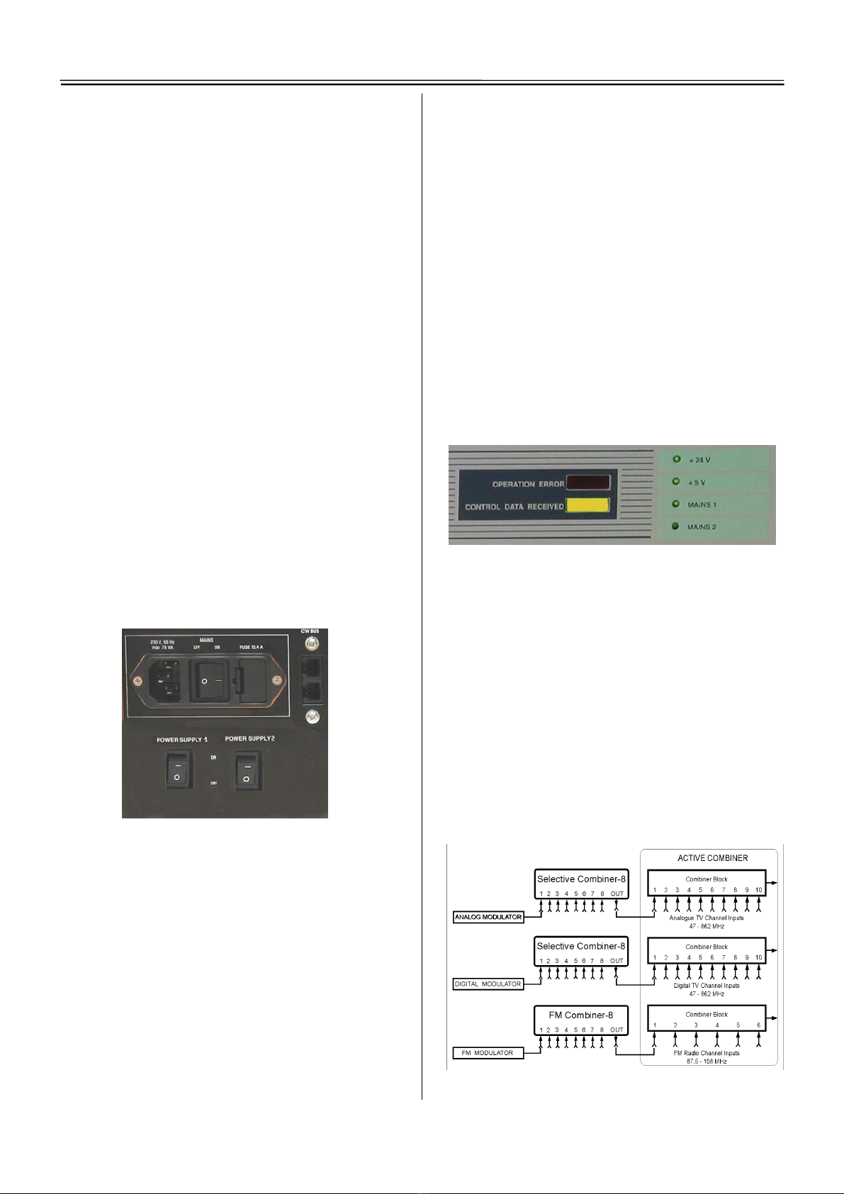
In order to achieve excellent carrier-to-noise ratio,
the output signals of the analogue and digital TV
modulators are to be connected to the ACTIVE
COMBINER through CW-307X SELECTIVE
COMBINER-8 units.
At combining FM radio signals, there is no need for
filtering by channel, thus the CW-307R FM
COMBINER-8 can be used. In the ACTIVE
COBINER, the output amplifier of the FM radio
channel combiner module is followed by a 87.8-108
MHz bandpass filter.
For mounting the eight-input combiners in the in-
strument rack cabinet, CW-3007 COMBINER
ADAPTER mounting frames are available.
Fig. 1. Selective combining of the headend’s output signals
2
ACTIVE COMBINER CW-4076
CABLING
The interconnections between the units have to be
made with high quality, low attenuation cables. Such
cables (CW-3931 ... 34) and cable sets are included in
our company's product range, too.
Connecting cables made by the system installer can
also be used, however they must be made of high
quality cable. For making special cables, we offer
cables and connectors in a large choice.
At cabling always use the shortest possible cables.
Especially the cables connecting the converter and
modulator outputs to the inputs of the passive com-
biners must be very short. For connecting the outputs
of the passive combiners with the inputs of the
ACTIVE COMBINER longer cables are permitted to
be used.
After the cabling has been finalized, it is advisable
to mark all cables at both ends. This can easily be
accomplished using the CW-1940 CABLE LABEL
SET. Here, the identification mark will be written on
the mat white side, then the self-adhesive label will
be stuck on the cable.
LEVEL ADJUSTMENT
After having installed and cabled the system, switch
on all units and perform the adjustment of the levels
of the system.
The output level is to be set according to the number
of the TV channels. Transmitting 80 TV channels and
48 radio channels, the nominal level of the high level
output can be 112 dBµV. Adjust the level of the digi-
tal channels with 64 QAM by 10-15 dB, and the
nominal output level of the radio channels by 10 dB
below the level of the analogue TV channels.
Measuring the nominal level of the digital chan-
nels with spectrum analyzer:
The actual level of the QAM signal is established by
adding a correction value to the spectrum analyzer
reading. For a digital signal of 8 MHz channel band-
width, at 100 kHz spectrum analyzer resolution
bandwidth (RB), the correction value is 21 dB, thus
the actual level of the signal is:
UQAM [dB] = Spectrum analyzer reading [dB] + 21 dB
For the example of Fig. 2:
UQAM = 99.78 + 21 = 120.78 dBµV
Correction values for the most frequent cases:
Fig. 2. Measuring the signal level of the digital channel
with spectrum analyzer
The output levels can be adjusted with screwdriver
attenuators on the rear panel.
Recommended sequence of adjusting the output levels:
1. Analogue channels.
2. Digital channels.
3. FM radio channels.
4. Adjusting the level of the signal combined of the
above channels, using the OUTPUT LEVEL at-
tenuator.
ADDITIONAL INFORMATION
1. The main output (OUT) of the ‘REVERSE PATH
OUTPUTS 5-65 MHz’ module has to be termi-
nated with a 75 ΩF-type termination plug.
2. The main output (OUT) of the ‘LOW LEVEL
OUTPUTS 47-862 MHz’ module has to be termi-
nated with a 75 ΩF-type termination plug.
3. The main output of the ’HIGH LEVEL
OUTPUTS 85-862 MHz’ module has to be termi-
nated with a 75 ΩF-type termination plug, when
measuring signal level at the CONTROL
OUTPUT.
4. The unused inputs of the ACTIVE COMBINER
should be terminated with 75 ΩF-type termina-
tion plugs, for having an amplitude response less
by several dBs.
GENERAL INFORMATION
The type number and serial number of the unit is
marked in a label on the unit’s side cover.
The ACTIVE COMBINER needs no adjustment, it is
sufficient to check up the adjustments once in a year.
RB Correction value
30 kHz 26 dB
100 kHz 21 dB
300 kHz 16 dB
1 MHz 11 dB
3 MHz 6 dB
Dear Customer!
We hope, this guide will effectively support you in
your job. Should you have any question when using
the unit, our experts are at your disposal at any time.
3
ACTIVE COMBINER CW-4076
Fig. 3. Block diagram of the CW-4076 ACTIVE COMBINER
CableWorld Ltd. H-1116 Budapest, Tel.: + 36 1 204 7815
Kondorfa u. 6/B Fax: + 36 1 204 7839
Hungary H-1519 Budapest. Pf. 418, Hungary
E-mail: [email protected]
Internet: www.cableworld.hu

Other CableWorld Media Converter manuals

CableWorld CW-4988 User manual

CableWorld

CableWorld CW-4988 User manual

CableWorld CW-4941 User manual

CableWorld

CableWorld CW-4941 User manual

CableWorld CW-4000 Series User manual

CableWorld

CableWorld CW-4000 Series User manual

CableWorld CW-4512 User manual

CableWorld

CableWorld CW-4512 User manual

Popular Media Converter manuals by other brands

TR-Electronic A 130 Series user manual

TR-Electronic

TR-Electronic A 130 Series user manual

Ross Abekas AirCleaner ACL-A user manual

Ross

Ross Abekas AirCleaner ACL-A user manual

SurfLink Media 2 Operation manual

SurfLink

SurfLink Media 2 Operation manual

Converters.TV CM-347 Operation manuals

Converters.TV

Converters.TV CM-347 Operation manuals

Kramer WP-SW2-EN7 quick start guide

Kramer

Kramer WP-SW2-EN7 quick start guide

Mitsubishi Electric P93E Operation manual

Mitsubishi Electric

Mitsubishi Electric P93E Operation manual

GE Security MCE-Coax user manual

GE Security

GE Security MCE-Coax user manual

XL Systems 0001821 quick start guide

XL Systems

XL Systems 0001821 quick start guide

EUCHIPS PX24601 manual

EUCHIPS

EUCHIPS PX24601 manual

MuxLab 500001 Quick installation guide

MuxLab

MuxLab 500001 Quick installation guide

FIAL 2316 manual

FIAL

FIAL 2316 manual

Harman Kardon MAS 102 owner's manual

Harman Kardon

Harman Kardon MAS 102 owner's manual

YOKOGAWA FLXA402 user manual

YOKOGAWA

YOKOGAWA FLXA402 user manual

Digitrax DN163A2 manual

Digitrax

Digitrax DN163A2 manual

Converters.TV 444 Operation manual

Converters.TV

Converters.TV 444 Operation manual

Cyrus ONE Cast User instructions

Cyrus

Cyrus ONE Cast User instructions

Trust TELEVIEWER V2 manual

Trust

Trust TELEVIEWER V2 manual

Baumer Hubner Berlin PMG10 Mounting and operating instructions

Baumer

Baumer Hubner Berlin PMG10 Mounting and operating instructions

manuals.online logo
manuals.online logoBrands
  • About & Mission
  • Contact us
  • Privacy Policy
  • Terms and Conditions

Copyright 2025 Manuals.Online. All Rights Reserved.