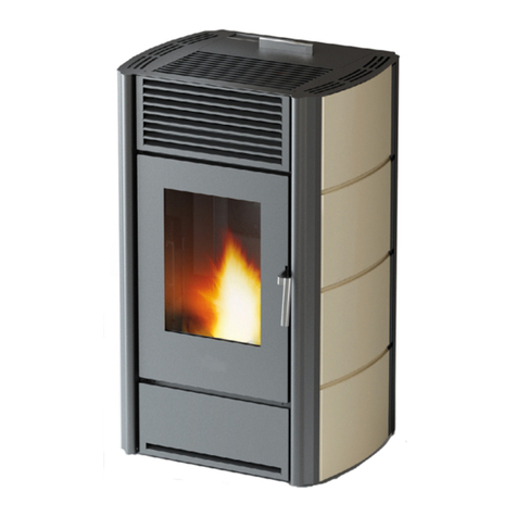
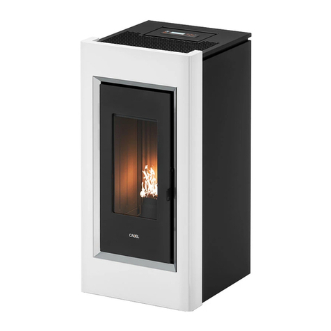
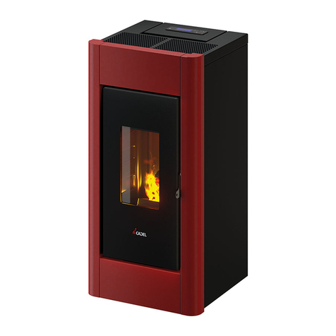
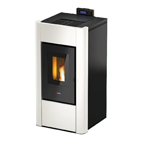
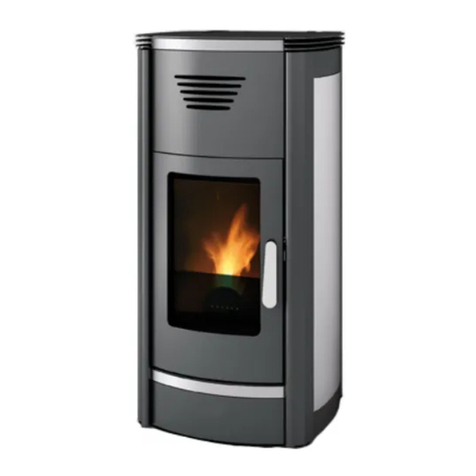
Cadel WALL 9 kW User manual

©2015 CADEL srl | All rights reserved – tutti i diritti riservati
en PELLET STOVE
installation, use and maintenance manual
nl PELLETKACHEL
handleiding voor installatie, gebruik en onderhoud
wall - small - style

2WALL - SMALL - STYLE
EN
Summary
1 MANUAL SIMBOLOGY ......................................... 3
2 DEAR CUSTOMER ................................................. 3
3 CAUTIONS ............................................................ 3
4 SAFETY REQUIREMENTS ........................................ 4
5 WARRANTY CONDITIONS .................................... 5
6 SPARE PARTS......................................................... 6
7
WARNINGS FOR THE CORRECT DISPOSAL OF THE PRODUCT ....
6
8 PACKAGING AND HANDLING............................ 6
8.1 PACKAGING ....................................................6
8.2 STOVE HANDLING............................................ 6
9 CHIMNEY FLUE ..................................................... 6
9.1 INTRODUCTION ................................................6
9.2 CHIMNEY FLUE..................................................7
9.3 TECHNICAL FEATURES...................................... 7
9.4 HEIGHT-DEPRESSION ........................................ 8
9.5 MAINTENANCE.................................................8
9.6 CHIMNEY POT................................................... 8
9.7 CHIMNEY COMPONENTS ................................ 9
9.8 EXTERNAL AIR INLET.......................................... 9
9.9 COMBUSTION AIR DRAWN DIRECTLY FROM
OUTSIDE.................................................................. 10
9.10 CHIMNEY FLUE CONNECTION ..................... 11
9.11 EXAMPLES OF CORRECT INSTALLATION...... 12
10 FUEL..................................................................... 13
10.1 FUEL................................................................ 13
11 INSTALLATION .................................................... 14
11.1 INTRODUCTION .............................................14
11.2 OVERALL DIMENSIONS ................................. 14
11.3 GENERAL INSTALLATION............................... 16
11.4
WALL MOUNTING (WALL-SMALL MODELS)....
16
11.5 SAFETY FIXING ...............................................18
11.6
PANELS ASSEMBLY (WALL - SMALL MODEL)
.... 18
11.7 PANELS ASSEMBLY (STYLE MODEL).............. 19
11.8 ELECTRIC CONNECTION ............................ 19
11.9
CONNECTION TO THE EXTERNAL THERMOSTAT....
20
11.10 VENTILATION ................................................20
11.11 PARTIAL DUCTING SYSTEM.......................... 20
11.12 FUNNEL CANALIZATION MOUNTING ......... 20
12 USE ...................................................................... 21
12.1 INTRODUCTION .............................................21
12.2 CONTROL PANEL .......................................... 21
12.3 USER MENU ....................................................22
12.4 START UP ........................................................ 23
12.5 STOVE ADJUSTMENT ..................................... 23
12.6 FAILED IGNITION............................................23
12.7 POWER FAILURE ............................................24
12.8 TEMPERATURE SETTING ................................. 24
12.9 FUME TEMPERATURE...................................... 24
12.10 SWITCHING OFF........................................... 24
12.11 CLOCK SETTING...........................................24
12.12 DAILY PROGRAMMING .............................. 24
12.13 WEEKEND PROGRAMMING........................ 24
12.14 WEEKLY PROGRAMMING ........................... 24
12.15 PELLET SUPPLY ..............................................25
12.16 REMOTE CONTROL...................................... 25
13 SAFETY SYSTEM................................................... 26
13.1 INTRODUCTION .............................................26
13.2 "BLACK OUT" ALARM .................................... 26
13.3 "EXHAUST PROBE" ALARM ............................ 26
13.4 "HOT EXHAUST" ALARM................................. 26
13.5 "FAN FAILURE" ALARM .................................. 26
13.6 "FAILED IGNITION" ALARM............................ 26
13.7 "NO PELLET" ALARM ...................................... 26
13.8 "THERMAL SAFETY" ALARM ........................... 26
13.9 "FAILURE DEPRESS" ALARM ........................... 27
14 MAINTEINANCE.................................................. 27
14.1 INTRODUCTION .............................................27
14.2
BURNING POT AND ASH TRAY CLEANING
..... 27
14.3 HOPPER AND AUGER CLEANING................ 28
14.4 FUME CHAMBER CLEANING ........................ 28
14.5 FUME CONDUIT CLEANING.......................... 29
14.6 FUME FAN CLEANING................................... 29
14.7 ROOM FAN CLEANING................................. 30
14.8 FUME PIPES ANNUAL CLEANING.................. 30
14.9 GENERAL CLEANING.................................... 30
14.10 CLEANING OF PAINTED METAL PANELS .... 30
14.11
CLEANING OF CERAMIC AND STONE PANELS
... 31
14.12 GASKET REPLACEMENT ............................... 31
14.13 GLASS CLEANING........................................ 31
15 IN CASE OF ANOMALY...................................... 31
15.1 ALARMS ......................................................... 31
15.2 PROBLEM SOLVING ...................................... 34
16 TECHNICAL DATAS............................................. 36
16.1 REPAIR INFORMATION .................................. 36
16.2 FEATURES .......................................................37
3
WALL - SMALL - STYLE
EN
1 MANUAL SIMBOLOGY
• The icons with the stylized gures indicates whom the subject dealt in the paragraph is addressed to (between
the User and/or the Authorized Technician and/or the Specialized Stove-repairer).
• WARNING symbols indicates an important note.
USER
AUTHORISED TECHNICIAN
(ONLY to interpret or the Stove-manufacturer or the Authorized
Technician of Technical Assistance Service approved by the Stove-
manufacturer)
SPECIALIZED STOVE-REPAIRER
CAUTION:
READ CAREFULLY THE NOTE
CAUTION:
DANGER OR IRREVERSIBLE DAMAGE POSSIBILITY
2 DEAR CUSTOMER
• Our products are designed and manufactured in compliance with standards EN 13240 for wood stoves,
EN 14785 for pellet stoves, EN 13229 for re places, EN 12815 for wood cooker stoves, C.P.R. 305/2011 for
manufacturing products, Re n.1935/2004 for materials and objects which are in contact with foods, Dir.
2006/95/CEE for low tension, Dir.2004/108/EC for Electromagnetic compatibility.
• Read carefully the instruction contained in this manual to obtain the best efciency.
• This instruction manual is an integral part of the product: make sure it is delivered with the appliance also in
case of sold to others. In case of loss please ask a copy to your local Technical Assistance Service.
In Italy biomass system installation below 35 kW must comply with MD 37/08. Every qualied
installer who own these requirements, has to issue the certicate of conformity for the
installed system ("system" means: stove + chimney + air inlet).
• According to (EU) No. 305/2011 regulation, the " Declaration of Performance" is available online at the web
sites:
- www.cadelsrl.com
- www.free-point.it
3 CAUTIONS
• All the pictures carried in this manual are only for indicative and explanatory purpose and could therefore
slightly differ from your appliance.
• The referring appliance is those you purchased.
• In case of doubts or difculties in the comprehension or for problems not described in this manual, please
promptly contact your distributor or installer.

4WALL - SMALL - STYLE
EN
4 SAFETY REQUIREMENTS
• Installation, electrical connection, functional verication and maintenance must
only be performed by qualied or authorised personnel.
• Live electrical parts: disconnect the product from the 230V power supply before performing
any maintenance operation. Only power the product after completing assembly.
• Special maintenance must only be performed by authorised and qualied
personnel.
• All local regulations, including those referring to national European standards, must
be respected during appliance installation.
• The manufacturer declines any responsibility in case of installation which are not
in compliance with current regulations, in case of a wrong room ventilation system,
in case of an electric connection which is not in compliance with regulations and in
case of a wrong use of the appliance.
• It is forbidden to install the stove in bedrooms, bathrooms and in rooms used for
storing combustible materials and in one-room ats.
• The installation in one-room ats is allowed if they are in sealed chamber.
• In any case the stove must not be installed in rooms where it can get in touch with
water or water splashes because this can cause burn hazards and short-circuit.
• Please check that the oor has an adequate load capacity. If the existing one does
not satisfy this requirement, appropriate measure should be provided (for example a
plate for distributing the load).
• For safety re regulations the distances from ammable or sensible to heat objects
(sofas, pieces of furniture, wooden covering, etc...) must be respected.
• If there are highly ammable objects (curtains, tted carpet, etc...), all these
distances must be further increased with 1 meter.
• The electrical cable must not get in touch with the fume exhaust pipe and nor with
every other part of the stove.
• The user, or whoever is operating the product, must read and fully understand the
contents of this installation and use guide before performing any operation. Errors or
incorrect settings can cause hazardous conditions and/or poor operation.
• The type of fuel to use is only the pellets.
• Do not use the appliance as waste inceneretor.
• Do not place laundry on the product to dry. Any clothes horses or similar objects
must be kept at a safe distance from the product. Fire hazard.
• It is forbidden to operate the product with the door open or the glass broken.
• It is forbidden to modify the appliance without authorization.
• Do not use ammable liquids during the ignition (alcool, petrol, oil, etc...).
• After a failed ignition the burning pot must be empty from the amassed pellets,
before starting the stove up again.
• The pellet hopper must always be closed with its own lid.
• Before of every intervention leave the re completely extinguish till the cooling and
always disconnect the plug from the electric socket.
• This appliance can be used by children aged from 8 years and above and persons
with reduced physical, sensory or mental capabilities or lack of experience and
knowledge if they have been given supervision or instruction concerning use of the
appliance in a safe way and understand the hazards involved. Children shall not play
with the appliance. Cleaning and user maintenance shall not be made by children
without supervision.
• Packaging are not toys and could cause suffocation or strangulation and other
health hazards! People (childreen included) with reduced mobility, psycological
deseases or without experience and knowledge must be kept away from packaging.
The stove is not a toy.
• Childreen must be constantly overseen in order to assure that they do not play
with the appliance.
• During its running, the stove reaches high temperatures: keep away childreen and

5
WALL - SMALL - STYLE
EN
animals and for your safety please use appropriate reproof devices, such as heat-
protecting gloves.
• If the auger is blocked by a foreign object (for example: nails), and if it needs to
be cleaned, do not remove the hand rejector and do not touch the auger. Please
contact the Technical Assistance service.
• The hand rejector can be removed exclusively by an authorized technician.
• The chimney ue must be cleaned, since the soot and unburnt oil deposits reduce
its section so blocking the draught. In great quantities they can are up.
• If the pellets are of bad quality (if contains sizing agents, oils, varnishes, plastic
remains or if it is mealy), deposits will form along pellets drop pipe during the running.
When the stove is switched off, these remains could form little hot coals that rising
along the pipe could reach the pellets on the hopper burning them and creating a
thick and harmful smoke inside the room. Please always keep the hopper closed with
its own lid. If the pipe is sooty, please clean it.
• In case it would be necessary to extinguish the re emitted by the stove or by the
chimney ue, use a re-extinguisher or contact the remen. Do not use water to
extinguish the re inside the burning pot.
5 WARRANTY CONDITIONS
The company guarantees the product, with the exception of elements subject to normal wear listed below, for
a period of 2 (two) years from the date of purchase attested by:
• a document to serve as proof of purchase (invoice and/or receipt) that shows the name of the vendor and
the date on which the purchase was made;
• forwarding of the completed certicate of guarantee within 8 days of purchase.
Furthermore, the product must be installed and started by specialised personnel who must, where provided,
issue a declaration of conformity of the plant and of the proper functioning of the product, for the warranty to
be valid and effective.
We recommend testing the product before completion with the relative nishes (claddings, painting of walls, etc.).
Installations not meeting the current standards, improper use and lack of maintenance as expected by the
manufacturer, void the product warranty.
The guarantee is valid on the condition that the instructions and warnings contained in the use and maintenance
manual are observed, and therefore the product is used correctly.
The replacement of the entire system or the repair of one of its components does not extend the guarantee
period, and the original expiry date remains unchanged.
The guarantee covers the replacement or free repair of parts recognised as being faulty at source due to
manufacturing defects.
To benet from the guarantee, in the event of a fault, the customer must have the guarantee certicate and
present it with the proof of purchase document to the Technical Assistance Ofce.
The guarantee does not cover malfunctions and/or damage to the appliance that arise due to the following causes:
• Damage caused during transportation or relocation.
• All parts that develop faults due to negligence or improper use, incorrect maintenance, installation that does
not comply with the manufacturer's instructions (always refer to the installation and use manual provided with
the appliance).
• Incorrect dimensioning with regards to the use or faults in the installation or failure to adopt the necessary
devices to guarantee proper execution.
• Improper overheating of the equipment, use of fuels not conforming to the types and quantities indicated in
the instructions provided.
• Further damage caused by incorrect user interventions in an attempt to x the initial fault.
• Worsening of the damage due to the continued use of the equipment by the user, once the defect has been
noticed.
• In the presence of a boiler, any corrosions, incrustations or breaks caused by water ow, condensation,
hardness or acidity of the water, improperly performed descaling treatments, lack of water, mud or limescale
deposits.
• Inefciency of chimneys, ues or parts of the plant affecting the equipment.
• Damage caused by tampering with the appliance, atmospheric agents, natural disasters, vandalism,
electrical discharges, res, faults in the electric and/or hydraulic system.
• Failure to have the stove cleaned on an annual basis by an authorised technician or qualied personnel will
result in the loss of the warranty.
Also excluded from this guarantee are:
• Parts subject to normal wear such as gaskets, glass, claddings and cast iron grids, painted, chrome-plated or
gilded parts, handles and electric cables, bulbs, indicator lights, knobs, all parts which can be removed from
the hearth.
• Variations in colour of the painted or ceramic/serpentine parts and craquelure ceramics as they are natural
characteristics of the material and product use.
• Masonry work.

6WALL - SMALL - STYLE
EN
• Plant parts (if present) not supplied by the manufacturer.
Any technical interventions on the product to eliminate the above-said defects and consequent damages must
be agreed upon with the Technical Assistance Centre, who reserves the right to accept the relative appointment
or not. However, said interventions will not be carried out under warranty but as technical assistance to be
granted at part of any eventual and specic agreed conditions and in accordance with the fee in force for the
work to be carried out.
The user will also be charged for any costs incurred to remedy the incorrect technical interventions, tampering
or damage to the appliance, not attributable to original faults.
Save for the legal or regulatory limits, the guarantee does not cover the containment of atmospheric and
acoustic pollution.
The company declines all liability for any damage which may be caused, directly or indirectly, to persons,
animals or objects as a consequence of non compliance with any prescription specied in the manual, especially
warnings regarding installation, use and maintenance of the appliance.
6 SPARE PARTS
For each repair or adjustment which should be necessary, please contact the dealer where you purchased your
stove or your nearest Technical Assistance Service, specifying:
• Appliance model
• Serial number
• Type of problem
Use only original spare parts which you can nd at our Technical Assistance Services.
7 WARNINGS FOR THE CORRECT DISPOSAL OF THE PRODUCT
The owner is the sole party responsible for demolishing and disposing of the product. This must be performed in
compliance with laws related to safety and environmental protection in force in his/her country.
At the end of its working life, the product must not be disposed of as urban waste.
It must be taken to a special differentiated waste collection centre set up by the local authorities or to a retailer
that provides this service.
Separating and recycling prevents potential negative effects on the environment and health (often caused by
inappropriately disposing of product parts). It also allows materials to be recovered in order to obtain signicant
savings in energy and resources.
8 PACKAGING AND HANDLING
8.1 PACKAGING
• The packaging is made up of recyclable cardboard boxes according to RESY standards, recyclable
expanded polystyrene inserts and wooden pallets.
• All packaging materials can be re-used for a similar use or eventually discharged as waste assimilable to the
municipal solid ones, in accordance with current regulations.
• After having removed the packaging please assure you about the integrity of the product.
8.2 STOVE HANDLING
Both whether the stove is packed or not it is necessary to observe the following instructions for handling and
transporting the stove from its sale point to its installation point and for any future movements:
• The stove must be handled with idoneous means paying attention to the existing safety regulations;
• do not turn the stove upside down and/or upset it on one side, but keep it in vertical position or as accorded
with the constructor instructions;
• if the stove is made up of ceramic, stone, glass or any particularly fragile material components, all must be
moved with the utmost care.
9 CHIMNEY FLUE
9.1 INTRODUCTION
This chapter about the Chimney Flue has been drawn up in cooperation with Assocosma (www.assocosma.org)
and is based on European Standards (EN 15287 - EN 13384 - EN 1856 - EN 1443) and UNI 10683:2012.
It provides instructions for a good and correct execution of the chimney ue but it does not absolutely replace
the current standards which the qualied manufacturer/installer should comply with.

7
WALL - SMALL - STYLE
EN
9.2 CHIMNEY FLUE
Fig. 1 - Chimney Flues
LEGEND Fig. 1 page 7
1Chimney ue with insulated stainless-steel pipes
2Chimney ue on the existing chimney
3Inspection plug
4Inspection door
5≥ 3,5 mt
• The chimney ue or chimney is of great importance for the correct running of the heating appliance.
• It is fundamental that the chimney ue is perfectly built and always maintained with a perfect efciency.
• The chimney ue must be sole (see Fig. 1 page 7) with insulated stainless-steel pipes (1) or installed on the
existing chimney ue (2).
• Both this solutions must be endowed with an inspection plug (3) and/or an inspection door (4).
9.3 TECHNICAL FEATURES
Fig. 2 - Inclined roof
LEGEND Fig. 2 page 7
1Height over the ridge of the roof = 0,5 mt
2Roof inclination ≥ 10°
390°
4Measured distance at 90° from the roof surface = 1,3 mt
• The chimney ue must be sealed from fumes.
• It must have a vertical run without narrowing. It must be realized with fume and condensation resistant

8WALL - SMALL - STYLE
EN
materials with thermal insulation and able to last against usual mechanical stresses.
It must be insulated to avoid condensation and to reduce fume cooling effects.
• The stove must be spaced out from fuels or ammable materials with an air gap or with insulating materials.
Check the distance with the chimney manufacturer.
• The chimney entrance must be placed in the same room where the appliance is installed or otherwise in
the adjacent room and it must be provided with a solid and condensation collection chamber under the
entrance, accessible through the sealed metal gate.
• Auxiliary exhaust fans cannot be installed neither along the chimney nor on the chimney pot.
• The inner section of the chimney ue can be round (the best one) or square and the jointed sides must have
a minimum radius of 20 mm.
• The section dimension must be:
•minimun Ø100 mm (for stoves up to 8.5 kw)
•minimun Ø120 mm (for stoves to 9 kw up)
•recommended max Ø180 mm
• Made the efciency of the chimney ue overhauled by an expert stove-repairer and if necessary cover the
chimney ue with materials in compliance with current regulations.
• The ue system must be placed on the roof.
• The chimney ue must be provided CE in accordance with EN 1443 regulation. Please nd attached an
example of label:
Fig. 3 - Example of label
9.4 HEIGHT-DEPRESSION
The depression (draught) of a chimney ue depends also on its height. Check the depression with the values
provided at FEATURES page 37. Minimum height 3,5 meters.
9.5 MAINTENANCE
• The fumes extraction pipes (fumes conduit + chimney ue + chimney pot) must always be cleaned, scrubbed
and checked by an expert stove-repairer, in compliance with current regulations, with the instructions of the
stove-manufacturer and the directives of your insurance company.
• In case of doubts, please follow the most restrictive regulations.
• Have your chimney ue and chimney pot checked and cleaned by an expert chimney sweep at least once
a week. The chimney sweep has to release a written declaration about the security of the system.
• Not cleaning compromise safety.
9.6 CHIMNEY POT
Fig. 4 - Anti-wind chimney pots
The chimney pot is important for the correct running of the heating appliance:
• We recommend using an anti-wind chimney pot, see Fig. 4 page 8.
• The hole width for fumes exhaust must be the double of the chimney ue width and tted in a way that the
fume exhaust is assured also in case of wind.
• It should prevent the inltration of rain, snow and animals.

9
WALL - SMALL - STYLE
EN
• The outlet height in the atmosphere must be away from the reux area caused by the roof structure or by
obstacles laying nearby (see Fig. 2 page 7).
9.7 CHIMNEY COMPONENTS
Fig. 5 - Chimney components
LEGEND Fig. 5 page 9
1Chimney pot
2Fume outlet
3Chimney ue
4Termal insulation
5External wall
6Chimney union
7Fume pipe
8Heat generator
9Inspection door
10 T-union with inspection plug
9.8 EXTERNAL AIR INLET
Fig. 6 - Direct air inow
LEGEND Fig. 6 page 9
1Room to ventilate
2External air inlet

10 WALL - SMALL - STYLE
EN
• It is mandatory to have an appropriate air intake connected to the outside to bring to the stove the air
required for combustion.
• The air inow from outside to the inner occurs directly, through an opening on the external wall of the room
(see Fig. 6 page 9).
• Bedrooms, garages, and store of ammable materials are excluded.
• The air inlet should have a total net surface of 80 sqcm2: the aforesaid surface is to widen if inside the room
there are other activated appliances (for example: electric ventilators for foul air suction, cooker hoods, other
stoves, etc...) which depress the environment.
• At switched on appliance it is necessary to check that the pressure fall between the room and the outside
does not exceed 4,0 Pa value: if necessary widen the air inlet.
• The air inlet must be realized at a height close to the oor with an external grid against birds. In such a way it
cannot be obstructed by any object.
9.9 COMBUSTION AIR DRAWN DIRECTLY FROM OUTSIDE
Fig. 7 - Air intake for installation
LEGEND Fig. 7 page 10
1≥ 1,5 mt
2≥ 0,3 mt
3-3 Sectional view
4Shield grid
5Curve inlet to turn downwards
For products with a rated power of less than 6 kW it is not advisable to draw the combustion air from outside
through direct connection as this can cause combustion difculties.
For all other NON SEALED products we recommend that you connect through a pipe with a minimum diameter
of 50 mm and a maximum length of 1 m.
With this solution the external air intake vent (see EXTERNAL AIR INLET page 9) can be reduced from 80 cm2
to 67 cm2.
• Assembly of a concentric smoke extraction pipe is prohibited.
• During installation you must verify the minimum distances for the combustion air intake (see Fig. 7 page 10).
• On the outside wall it is necessary to install a 90° bend to protect the ow of combustion air by wind effects:
turn the beginning of the curve downward (see Fig. 7 page 10).
With this type of solution, if the burning is not optimal (scarcely oxygenated ame, glass that gets dirty quickly,
etc.) you may need to change the combustion parameters of the stove (consult an Authorized Technician) or
review the length and the type of connection made.
Check with local authorities if there are restrictive regulations regarding combustion air
intake: if present, they must be applied.

11
WALL - SMALL - STYLE
EN
9.10 CHIMNEY FLUE CONNECTION
Your pellet stove works through a fume draught forced by a fan. It is obligatory to check that all pipes are
realized in compliance with the following regulation on material selection: EN 1856-1, EN 1856-2 e UNI/TS 11278.
All must be effected by specialized personnel or companies as provided by UNI 10683:2012.
• The connection between the appliance and the chimney ue should be short in order to favor the draught
and to avoid condensation in the pipes.
• The fume conduit should be equivalent or longer than the outlet joint ones (Ø 80 mm).
• Some stove models are endowed with a lateral and/or back exhaust. Check that the unused exhaust is
sealed with the plug given with standard equipment.
SYSTEM TYPE Ø80 mm PIPE Ø100 mm PIPE
Minimum vertical length 1,5 mt 2 mt
Maximum length (with 1 union) 6,5 mt 8 mt
Maximum length (with 3 unions) 4,5 mt 6 mt
Maximum number of unions 3 3
Level section (minimum inclination 3%) 2 mt 2 mt
Installation at a height above 1200 m a.s.l. NO Obligatory
• Use a plate pipe for stoves of Ø80 mm or Ø100 mm depending on the type of system and with silicone gaskets.
• It is forbidden to use metal, bre cement or aluminium exible pipes.
• For change of direction it is obligatory always to use a union (with angle > 90°) with inspection plug which
enables an easy periodic cleaning of the pipes.
• Please assure you that after the cleaning the inspection plugs are sealed with its efcient gasket.
• It is forbidden to connect more appliances to the same fume conduit.
• Installation in double-walled ues (concentric system) is forbidden.
• It is forbidden to convey in the same fume conduit exhausts from overhanging cooker hoods.
• It is forbidden to exhaust ue gases directly from the wall towards the outside and closed spaces also at open
top (see Fig. 8 page 11).
Fig. 8 - Prohibition
• It is forbidden to connect any other appliance (wood stoves, cooker hoods, boilers, etc...).
• The fume conduit must be placed at a distance of minimum 500 mm from ammable or heat-susceptible
components.

12 WALL - SMALL - STYLE
EN
9.11 EXAMPLES OF CORRECT INSTALLATION
Fig. 9 - Example 1
LEGEND Fig. 9 page 12
1Insulating material
2Reduction from Ø100 to Ø80 mm
3Inspection plug
4Minimum safety distance = 0,5 mt
• Chimney ue installation Ø100/120 mm with an enlarged drilling for pipe transit.
Fig. 10 - Example 2
LEGEND Fig. 10 page 12
1Insulating material
2Inspection plug
3Chimney inspection entrance
4Minimum safety distance = 0,5 mt
5Inclination ≥ 3°
6Level section ≤ 1 mt
• Old chimney ue with an inserted pipe of minimum Ø100/120 mm and with an external door which enables
the chimney cleaning.

13
WALL - SMALL - STYLE
EN
Fig. 11 - Example 3
LEGEND Fig. 11 page 13
1Insulating material
2Inspection plug
3Minimum safety distance = 0,5 mt
• External chimney ue entirely made up of insulated stainless steel pipes, i.e. with double wall of minimum
Ø100/120 mm: all must be rmly attached to the wall. For chimney against wind effects please (see Fig. 4
page 8).
• Ducting system through T-unions which enables an easy cleaning without disassembling the pipes.
We recommend to check with your chimney ue manufacturer the safety distances which
must be respected and the type of insulating material. The aforesaid regulations are valid
also for holes made on the wall (EN 13501 - EN 13063 - EN 1856 - EN 1806 - EN 15827).
10 FUEL
10.1 FUEL
• Use top-quality pellets because they have inuence in the caloric value and in ash remains.
• Pellets features are: dimension Ø6-7mm (D06 Class), maximum lenght 40 mm, caloric value 5kWh/kg, humidity
≤ 10%, ash remains ≤ 0,7%, they must be correctly pressed and not much mealy, without sizing agents, resins
and other additives (it is advisable to use pellets in compliance with the regulation EN14961-2 type ENplus-A1).
• Not adequate pellets cause a bad combustion, a frequent burning pot obstruction and exhaust conduits
obstruction. Further it decreases the caloric value, soils the glass and increases consumptions and ash and
unburnt granules quantity.
Humid pellets cause a bad combustion and running, so please assure you that they are
stored in dry places and far at least one meter from the stove and/or any other source of
heat.
• It is advisable to try different type of pellets available on the market and to choose that which gives the best
performance.
• The use of bad quality pellets can damage the stove so that the warranty and manufacturer liability fall.
• On all our product are used high-quality materials such as stainless-steel, steel, cast iron, etc... These materials,
before being sold on the market, are tested in laboratory, but despite this on the components which enable
the pellets ow (auger) there could exist minimum differences in the material used, in roughness and porosity,
which could generate usual variations in fuel transportation (pellets), causing a ame raising or drapping with
a possible switching off at lower powers.
• Depending on the type of pellets it could be necessary a parameters adjustment, please contact an
Authorized Assistance Service.

14 WALL - SMALL - STYLE
EN
11 INSTALLATION
11.1 INTRODUCTION
• The assembly position must be chosen depending on environment, outlet, chimney ue.
• Check with local authorities if there are any restrictive regulations which regard the combustible air inlet,
room ventilation, fume exhaust system together with chimney ue and chimney pot.
• Check if there is the combustible air inlet.
• Check the probable presence of other stoves or appliances which could depress the room.
• Check at switched on stove if there is the presence of CO in the room.
• Check if the chimney has the necessary draught.
• Check if during the fume passage all has been executed in safety (probable fume losses and distances from
ammable materials, etc.…).
• The installation of the appliance must enable an easy access for appliance, fume exhaust pipes and chimney
ue cleaning.
• The installation must enable en easy access to the electric connection plug (see ELECTRIC CONNECTION
page 19).
• To install more appliances, the external air inlet must be correctly dimensioned (see FEATURES page 37).
11.2 OVERALL DIMENSIONS
Fig. 12 - General dimensions: Wall/Small
LEGEND Fig. 12 page 14
1Hole combustion air inlet from indoor environment d.4 cm
2Hole combustion air inlet from outdoor environment d.4 cm
3Exhaust fumes d.8 cm
4Hot air outlet d.8 cm
596 cm
687,5 cm
715,5 cm
826 cm
980 cm
10 7,3 cm
11 17.3 cm
12 17.2 cm
13 8 cm
14 87,8 cm
15 85 cm

15
WALL - SMALL - STYLE
EN
LEGEND Fig. 12 page 14
16 27 cm
17 13,3 cm
18 85,5 cm
19 86,3 cm
20 24,4 cm
21 20,2 cm
Fig. 13 - General dimensions: Style
LEGEND Fig. 13 page 15
1Hole combustion air inlet from indoor environment d.4 cm
2Hole combustion air inlet from outdoor environment d.4 cm
3Exhaust fumes d.8 cm
4Hot air outlet d.8 cm
594,5 cm
698,5 cm
727 cm
880,5 cm
917 cm
10 17 cm
11 7,3 cm
12 88 cm
13 85 cm
14 27,5 cm
15 14 cm
16 85,5 cm
17 86,5 cm
18 24,5 cm
19 20,2 cm

16 WALL - SMALL - STYLE
EN
11.3 GENERAL INSTALLATION
Fig. 14 - General installation
LEGEND Fig. 14 page 16
1Stove
2Minimum lateral distance = 300 mm
3Minimum rear distance = 200 mm
4Minimum front distance = 1000 mm
• It is obligatory to install the stove away from walls and/or pieces of furniture, with a minimum air ow of 300
mm on the sides and 200 mm on the back, to enable an ecient appliance cooling and a good distribution
of heat in the room (see Fig. 14 page 16).
• If the walls are made up of ammable materials, check the safety distances (see Fig. 14 page 16).
• At maximum power check that the wall temperature does not ever exceed 80°C. If it would be necessary
please install a re resistant plate on the concerned walls.
• In some countries also masonring load-bearing walls are considered ammable.
11.4 WALL MOUNTING (WALL-SMALL MODELS)
The stove is suitable for wall mounting. The can be attached to a load-bearing wall in masonry (NOT plasterboard,
wood, etc...) suitable for the entire weight of the stove.
Fig. 15 - Wall mounting
LEGEND Fig. 15 page 16
1Stove
2Minimum lateral distance = 300 mm
3Minimum front distance = 1000 mm
• It is obligatory to install the stove away from walls and/or pieces of furniture, with a minimum air ow of 300
mm on the sides to enable an ecient appliance cooling and a good distribution of heat in the room (see
Fig. 15 page 16).
In some countries also masonring load-bearing walls are considered ammable.
If you want to x the stove to a non-ammable material wall, you need to x the support to the wall (the support
is provided with the stove).
• Call an expert to prepare the fumes outlet hole and the combustion air inlet hole.
• To x the rear support to the wall with metal plugs su1itable for the weight of the stove (see Fig. 16 page 17).

17
WALL - SMALL - STYLE
EN
Fig. 16 - Mounting on non-ammable wall
LEGEND Fig. 16 page 17
1695 mm
2248,5 mm
3260 mm
480 mm
5234 mm
6205 mm
7880 mm
8Fumes outlet hole d.120 mm
9Combustion air inlet hole d.80 mm
10 Wall support
11 Metal plugs
If the stove is to be xed to an inammable wall, it is compulsory to attach further support to the wall cod.
5013016 (the suppurt is NOT provided with the stove).
• Call an expert to prepare the fumes outlet hole and the combustion air inlet hole.
• To x the rear support to the wall with metal plugs su1itable for the weight of the stove (see Fig. 17 page 17).
Fig. 17 - Mounting on ammable wall
LEGEND Fig. 17 page 17
1695 mm

18 WALL - SMALL - STYLE
EN
LEGEND Fig. 17 page 17
2248,5 mm
3260 mm
480 mm
5234 mm
6205 mm
7880 mm
8735 mm
9228,5 mm
10 Wall support
11 Spacer (cod.5013016)
12 Combustion air inlet hole d.80 mm
13 Fumes outlet hole d.120 mm
14 Metal plugs
15 M8x20 bolt
11.5 SAFETY FIXING
The appliance must be installed by an authorized technician!
To avoid accidental tipping, x the stove to the wall with two plugs see Fig. 18 page 18.
Fig. 18 - Wall xing
11.6 PANELS ASSEMBLY (WALL - SMALL MODEL)
Assembly must be carried out by an authorised technician.
For panels installation, proceed as follows:
Fig. 19 - Panels assembly Fig. 20 - Panels xing

19
WALL - SMALL - STYLE
EN
• Insert the metal side panles from above, placing the two teeth on the special slots and pushing all the way
down (see Fig. 19 page 18).
• Use no.8 wrench to tightenthe two screws under the panel (see Fig. 20 page 18).
11.7 PANELS ASSEMBLY (STYLE MODEL)
Assembly must be carried out by an authorised technician.
For panels installation, proceed as follows:
Fig. 21 - Panels assembly Fig. 22 - Panels xing
• Insert the metal side panles from above, placing the teeth on the special slots and pushing all the way down
(see Fig. 21 page 19 and Fig. 22 page 19).
11.8 ELECTRIC CONNECTION
Warning: the appliance must be installed by an authorized technician!
• The electric connection occurs through a cable with plug put in an electric socket which is able to support
charge and tension specic of every model, as described in the technical datas table (see FEATURES page 37).
• The plug must be easily accessible when the appliance is installed.
• Please further assure you that your network is endowed with an efcient earth connection: if it does not exist
or if it is not efcient, please endow you with one in compliance with the law.
• Connect the supply cable rst on the back of the stove (see Fig. 23 page 19) and then at a wall electric
socket.
Fig. 23 - Electric socket with master switch
• The master switch O/I (see Fig. 23 page 19) is to open only to switch the stove on, otherwise it is advisable
to keep it off.
• Do not use extension cables.

20 WALL - SMALL - STYLE
EN
• If the feeder cable is damaged, it must be replaced by an authorized technician.
• When the stove is not going to be used for a long period of time, it advisable to remove the plug from the
socket on the wall.
11.9 CONNECTION TO THE EXTERNAL THERMOSTAT
The stove works through a thermostat probe placed in its inner. If you desire, the stove can be connected to an
external room thermostat. This operation must be executed by an authorized technician.
• External thermostat: "SET TEMP ROOM" a temperature which is round 7°C.
• External chronothermostat: "SET TEMP ROOM" a temperature which is round 7°C and desable the chrono
functions from the menu 03-01 "CHRONO ENABLE" ("OFF").
11.10 VENTILATION
• The stove is endowed with a ventilation system.
• The air blown from fans keeps the appliance at a low temperature range in order to avoid high stresses to the
materials which make it up.
• Do not cover the hot air outlet slits with any object to avoid stove’s overheating!
• The stove is not suitable for food cooking.
Fig. 24 - Do not cover air slits
11.11 PARTIAL DUCTING SYSTEM
• Removing the top nned grid and tting a special grille shaped to allow passage of the pipes, an 80mm pipe
can be tted to the hot air outlet, so that some of the air can be released into another small room.
• If necessary, t a small extractor to the pipe outlet to increase the amount of hot air released into the room.
We recommend to not use more than 1,5 meters of pipe, otherwise the hot air will lose its
effectiveness.
11.12 FUNNEL CANALIZATION MOUNTING
Proceed as follows:
Fig. 25 - Phase 1 Fig. 26 - Phase 2 Fig. 27 - Phase 3
This manual suits for next models
2
Table of contents
Languages:
Other Cadel Stove manuals

Cadel
Cadel nice Quick start guide

Cadel
Cadel PRINCE 11 User guide

Cadel
Cadel Cristal 7 Up User manual

Cadel
Cadel SFERA3 11KW User guide

Cadel
Cadel TILE3 MOON User manual

Cadel
Cadel ROXY User manual

Cadel
Cadel GRACE 7 User guide

Cadel
Cadel PRINCE 11 User manual

Cadel
Cadel INDIGO EVO User guide

Cadel
Cadel KOBE 11 User manual

Cadel
Cadel ARCO 7 T1 BI-FLUX User manual

Cadel
Cadel VEGA AIRTIGHT User manual

Cadel
Cadel Venus Plus Service manual

Cadel
Cadel LORD 7 User guide

Cadel
Cadel Martina User manual

Cadel
Cadel SWEET3 7 User manual

Cadel
Cadel SATURNO 16 User guide

Cadel
Cadel MITHOS3 PLUS 14 PS User manual

Cadel
Cadel AMARANTO 9 User guide

Cadel
Cadel VENUS Quick start guide