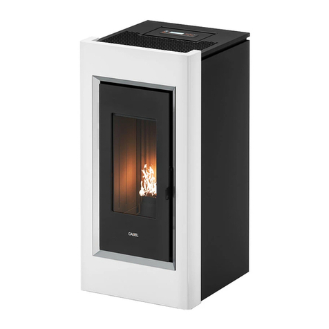
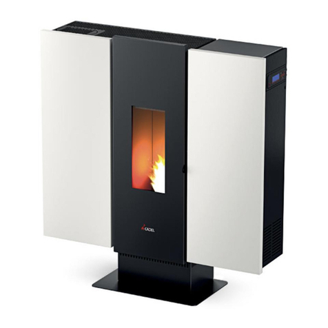
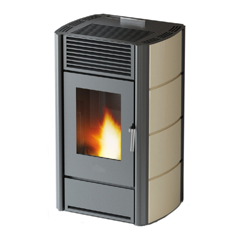
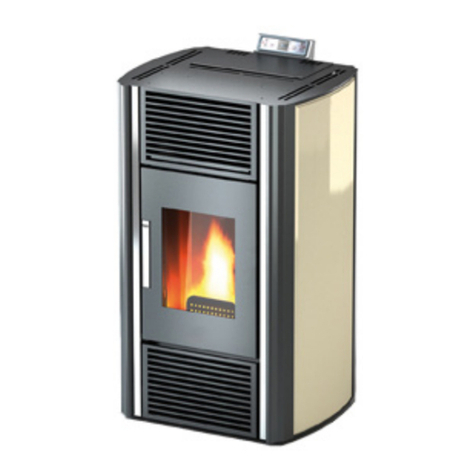
Cadel GO 11 User guide

INSTALLER MANUAL
Pellet Stove
EN new ©2023 CADEL srl | All rights reserved - Tutti i diritti riservati
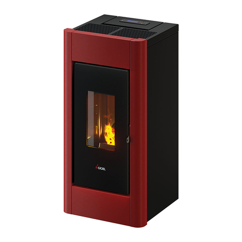
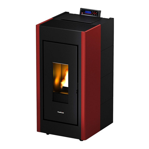
PRINCE 11 KOBE 11 FENICE 11
PRINCE PLUS 11 KOBE PLUS 11 FENICE PLUS 11
SPARK 11 INDACO 11 GO 11 ECLIPSE 11

KOBE - FENICE - SPARK - INDACO - PRINCE - GO - ECLIPSE
2
SUMMARY
1 MANUAL SIMBOLOGY....................................3
2 PACKAGING AND HANDLING..........................3
2.1 PACKAGING .............................................................3
2.2 REMOVING THE STOVE FROM THE PALLET ..............3
2.3 STOVE HANDLING....................................................4
3 CHIMNEY FLUE .............................................4
3.1 PREPARING THE SMOKE EXPULSION SYSTEM.........4
3.2 CHIMNEY COMPONENTS.........................................4
3.3 SMOKE DUCT SMOKE FITTING..............................5
3.4 FLUE CHIMNEY OR PIPED DUCT ...........................5
3.5 CHIMNEY POT..........................................................6
3.6 MAINTENANCE........................................................7
4 COMBUSTION AIR.........................................7
4.1 AIR INLET ................................................................7
4.2 COMBUSTIBLE AIR INLET FOR SEALEDCHAMBER
INSTALLATION ...................................................................8
5 EXAMPLES OF INSTALLATION DIAMETERS AND
LENGTHS TO BE SIZED ........................................9
6 INSTALLATION............................................10
6.1 INTRODUCTION.....................................................10
6.2 MINIMUM DISTANCES...........................................11
6.3 OVERALL DIMENSIONS .........................................12
6.4 STOVE DOOR REMOVAL/INSTALLATION................15
6.5 REMOVAL/ASSEMBLY OF SIDE PANELS PRINCE 11
PRINCE PLUS 11..............................................................15
6.6 REMOVAL/ASSEMBLY OF THE FRAME PRINCE 11
PRINCE PLUS 11..............................................................16
6.7 REMOVAL/ASSEMBLY OF SIDE PANELS FENICE 11
FENICE PLUS 11..............................................................16
6.8 REMOVAL/ASSEMBLY OF LOWER FRONT PANEL
FENICE 11 FENICE PLUS 11 .........................................17
6.9 REMOVAL/ASSEMBLY OF SIDE PANELS KOBE 11
KOBE PLUS 11.................................................................17
6.10 REMOVAL/ASSEMBLY OFTHE FRAME KOBE11 KOBE
PLUS 11 ..........................................................................18
6.11 1.2 REMOVAL/ASSEMBLY OF SIDE PANELS INDACO
11 ..............................................................................18
6.12 1 REMOVAL/ASSEMBLY OF SIDE PANELS SPARK 11
..............................................................................19
6.13 REMOVAL/ASSEMBLY OF THE FRAME GO 11......20
6.14 REMOVAL/ASSEMBLY OF SIDE PANELS ECLIPSE 11
..............................................................................20
6.15 REMOVAL/ASSEMBLY OF THE FRAME ECLIPSE 1121
6.16 REAR OR UPPER FUME EXHAUST..........................22
6.17 CONCENTRIC PIPEKIT ASSEMBLY.........................23
6.18 HOT HAIR DUCTING ONLY VALID FOR DUCTED
STOVES...........................................................................23
6.18.1 DUCTING SOLUTIONS:.........................................24
6.19 DUCTING DATA ......................................................26
6.20 ELECTRIC CONNECTION.........................................26
6.21 CONNECTION TO THE EXTERNAL THERMOSTAT.....27
6.22 STOVE CALIBRATION AND DEPRESSION
MEASUREMENT ...............................................................27
7 SPECIAL MAINTENANCE ..............................28
7.1 INTRODUCTION.....................................................28
7.2 FUME CHAMBER CLEANING..................................28
7.3 FUME CONDUIT CLEANING....................................29
7.4 FUME PASSAGE CLEANING....................................30
7.5 FUME FAN CLEANING............................................31
7.6 ROOM FAN CLEANING ...........................................31
8 IN CASE OF ANOMALY..................................32
8.1 PROBLEM SOLVING ...............................................32
9 TECHNICAL DATAS ......................................35
9.1 REPAIR INFORMATION ..........................................35
10 FEATURES ..................................................36
3
KOBE - FENICE - SPARK - INDACO - PRINCE - GO - ECLIPSE
1 MANUAL SIMBOLOGY
USER
AUTHORISED TECHNICIAN
(ONLY to interpret or the Stove-manufacturer or the Authorized Technician of
Technical Assistance Service approved by the Stove-manufacturer)
SPECIALIZED STOVE-REPAIRER
CAUTION:
READ CAREFULLY THE NOTE
CAUTION:
DANGER OR IRREVERSIBLE DAMAGE POSSIBILITY
• The icons with the stylized figures indicates whom the subject dealt in the paragraph is addressed to (between the User and/
or the AuthorizedTechnician and/or the Specialized Stove-repairer).
• WARNING symbols indicates an important note.
2 PACKAGING AND HANDLING
2.1 PACKAGING
• The packaging is made up of recyclable cardboard boxes according to RESY standards, recyclable expanded polystyrene inserts
and wooden pallets.
• All packaging materials can be re-used for a similar use or eventually discharged as waste assimilable to the municipal solid
ones, in accordance with current regulations.
• After having removed the packaging please assure you about the integrity of the product.
2.2 REMOVING THE STOVE FROM THE PALLET
Proceed as follows:
Fig. 1 - Bracket removal
• Remove the brackets which secure the feet of the stove (see Fig. 1). Then remove the stove from the pallet.

KOBE - FENICE - SPARK - INDACO - PRINCE - GO - ECLIPSE
4
2.3 STOVE HANDLING
Both whether the stove is packed or not it is necessary to observe the following instructions for handling and transporting the
stove from its sale point to its installation point and for any future movements:
• The stove must be handled with idoneous means paying attention to the existing safety regulations;
• do not turn the stove upside down and/or upset it on one side, but keep it in vertical position or as accorded with the construc-
tor instructions;
• if the stove is made up of ceramic, stone, glass or any particularly fragile material components, all must be moved with the
utmost care.
3 CHIMNEY FLUE
3.1 PREPARING THE SMOKE EXPULSION SYSTEM
The combustion product expulsion system is a particularly important element for the proper operation of the appliance and must
be correctly sized according to EN 13384-1.
Its creation/adaptation/verification must always be carried out by a legally qualified operator and must comply with the regula-
tions in force in the country where the appliance is installed.
The Manufacturer declines all liability for malfunctions caused by a badly sized and non-compliant smoke expulsion system.
3.2 CHIMNEY COMPONENTS
Fig. 2 - Chimney components
LEGEND Fig. 2
1Chimney pot
2Fume outlet
3Chimney flue
4Termal insulation
5External wall
6Chimney union
7Fume pipe
8Heat generator
9Inspection door
10 T-union with inspection plug

5
KOBE - FENICE - SPARK - INDACO - PRINCE - GO - ECLIPSE
3.3 SMOKE DUCT SMOKE FITTING
The smoke duct is the pipe that connects the appliance to the flue.
This smoke fitting must comply in particular with the following requirements:
• comply with product standard EN 1856-2;
• its cross-section must be of constant diameter and no less than that of the appliance outlet, from the firebox outlet up to the
connection in the flue;
• the horizontal section must be as short as possible and extend no more than 4 metres;
• the horizontal sections must have a minimum upward slope of 3%;
• changes of direction must have an angle no greater than 90° and be easy to inspect
• the number of changes of direction, including that for entry into the flue, and exclusion of the T in the event of a side or rear
outlet, must not exceed 3;
• it must be insulated if it passes outside the installation room
• it must not in any case cross rooms in which it is forbidden to install combustion appliances.
• the use of flexible metal and fibre cement or aluminium hoses is forbidden;
In any case, smoke ducts must be sealed against combustion products and any condensation. For this reason, it is recommended
to use pipes with silicone gaskets or similar sealing devices that withstand the operating temperatures of the appliance (e.g.T200
P1) and that by removing the gaskets, are stillT400 N1 G certified.
SYSTEM TYPE Ø80 mm PIPE Ø100 mm PIPE
Minimum vertical length 1,5 mt 2 mt
Maximum length (with 1 union) 6,5 mt 10 mt
Maximum length (with 3 unions) 4,5 mt 8 mt
Maximum number of unions 3 3
Level section (minimum inclination 3%) 4 mt 4 mt
Installation at a height above 1200 m a.s.l. NO Obligatory
3.4 FLUE CHIMNEY OR PIPED DUCT
When creating the flue, in particular comply with the following requirements:
• comply with the applicable product standard (EN 1856, EN 1857 EN 1457, EN 1806, EN 13063..);
• be made with suitable materials to ensure resistance to normal mechanical, chemical, thermal stresses and have adequate
thermal insulation in order to limit the formation of condensate;
• have a predominantly vertical configuration and be free of choke points along its entire length;
• be correctly spaced by air gaps and isolated from combustible materials;
• the flue inside the house must still be insulated and can be inserted in an air shaft provided it complies with the regulations
for piping;
• the smoke duct must be connected to the flue by means of aTee fitting with an inspectable collection chamber for the collec-
tion of soot and any condensate.
• where the sizing provides for wet operation, a suitable condensate collection and siphon discharge system must be set up.
We recommend checking the data plates of the flue for the safety distances that must be observed in
the presence of combustible materials and, if necessary, the type of insulating material to be used.
It is forbidden to connect the stove to a collective or shared flue with other combustion appliances or
with hood outlets.
It is forbidden to use the direct drain on the wall or towards indoor spaces and any other form of drain
not provided for by the regulation in force in the country of installation.

KOBE - FENICE - SPARK - INDACO - PRINCE - GO - ECLIPSE
6
Fig. 3 - Chimney Flues
LEGEND Fig. 3
1Chimney flue with insulated stainless-steel pipes
2Chimney flue on the existing chimney
3Inspection plug
4Inspection door
• The chimney flue must be provided CE in accordance with EN 1443 regulation. Please find attached an example of label:
Fig. 4 - Example of label
3.5 CHIMNEY POT
The chimneypot, meaning the end part of the flue, must meet the following characteristics:
• the smoke outlet section must be at least double the internal section of the chimney;
• prevent the penetration of rain or snow;
• ensure the outlet of smoke even in the event of wind (windproof chimneypot);
• the height of outflow must be beyond the reflux area (**) (refer to national regulations to identify the reflux area);
• always be built at a distance from antennas or dishes, and never be used as a support.
(**) unless there are specific national derogations (clearly specified in the corresponding instruction manual in English) which under
appropriate conditions allow it; in this case, strictly follow the product/installation requirements of the relative regulations/technical
specifications/legislation in force in that country.

7
KOBE - FENICE - SPARK - INDACO - PRINCE - GO - ECLIPSE
Fig. 5 - Anti-wind chimney pots
Fig. 6 - Reux area
3.6 MAINTENANCE
• The fumes extraction pipes (fumes conduit + chimney flue + chimney pot) must always be cleaned, scrubbed and checked
by an expert stove-repairer, in compliance with current regulations, with the instructions of the stove-manufacturer and the
directives of your insurance company.
• In case of doubts, please follow the most restrictive regulations.
• Have your chimney flue and chimney pot checked and cleaned by an expert chimney sweep at least once a week.The chimney
sweep has to release a written declaration about the security of the system.
• Not cleaning compromise safety.
4 COMBUSTION AIR
4.1 AIR INLET
It is mandatory to provide an adequate external air inlet that supplies the combustion air required for the product to work properly.
The flow of air between the outside and the installation room can take place with a free air inlet or by channelling the air directly
to the outside (***).
The free air inlet must:
• be made at floor level;
• always be protected with an outer grille and in such a way that it cannot be obstructed by any object;
• have a minimum total free area of 80 cm2(net of the grille);
The presence of other suction devices (e.g.: vmc, electric fan for stale air extraction, kitchen hood, other stoves, etc.), in the same
room could cause negative pressure in the room. In this case, with the exception of sealed installations, one must verify that, with
all the equipment on, no more than 4 Pa of negative pressure is created inside the installation room with respect to the outside. If
necessary, increase the air inlet section.
It is possible to duct the air required for combustion to the outside by connecting the external air inlet directly with the combustion
air inlet which is usually found on the back of the appliance.
The duct must comply with the following dimensions (each 90° bend is equivalent to one linear metre):

KOBE - FENICE - SPARK - INDACO - PRINCE - GO - ECLIPSE
8
(***) In the event the combustion air is ducted on unsealed products, still verify that no more than 4 Pa of negative pressure is created
inside the installation room with respect to the outside, otherwise provide for an additional air intake in the room.
Below 15 kW:
Air duct diameter Maximum length (smooth duct) Maximum length (corrugated duct)
50 mm 2 m 1 m
60 mm 3 m 2 m
80 mm 7 m 4 m
100 mm 12 m 9 m
Above 15 kW:
Air duct diameter Maximum length (smooth duct) Maximum length (corrugated duct)
50 mm - -
60 mm 1 m -
80 mm 3 m 1 m
100 mm 7 m 4 m
Fig. 7 - Direct air inow Fig. 8 - Air inlet for sealed-chamber installation
LEGEND Fig. 7|Fig. 8
1Room to ventilate
2External air inlet
4Shield grid
5Curve inlet to turn downwards
4.2 COMBUSTIBLE AIR INLET FOR SEALEDCHAMBER INSTALLATION
How to connect to the stove in the sealed chamber with concentric system:
Fig. 9 - Phase1

9
KOBE - FENICE - SPARK - INDACO - PRINCE - GO - ECLIPSE
• Connect the air intake pipe to the combustion air pipe of the stove and tighten everything with a clamp (see [Fig. 9).
5 EXAMPLES OF INSTALLATION DIAMETERS AND LENGTHS TO BE SIZED
Fig. 10 - Chimney ue
1. Flue installation with hole for the passage of the pipe increased by: minimum 100mm around the pipe if next to non-flamma-
ble parts such as cement, brick, etc.; or minimum 300mm around the pipe (or as required by plate data) if next to flammable parts
such as wood etc. In both cases, install suitable insulation between the flue and the ceiling.
Always check and comply with the plate data of the flue, specifically the minimum safety distances from combustible materials.
The previous rules also apply for holes made in walls.
2. Old flue, pipe with the inclusion of an external access door for chimney cleaning.
3. External flue made of insulated stainless-steel pipes, i.e. with double walls: all securely mounted on the wall. With windproof
chimneypot.
4. Ducting system usingTee fittings that allow easy access for cleaning without having to remove the pipes.

KOBE - FENICE - SPARK - INDACO - PRINCE - GO - ECLIPSE
10
LEGEND Fig. 10
UInsulation
VPossible diameter increase
IInspection cap
SInspection access panel
PAir inlet
TTee fitting with inspection cap
ADistance from flammable material (smoke duct plate)
BMaximum 4 m
CMinimum 3° slope
DDistance from flammable material (appliance plate)
EReflux area
FAir ducting
The instructions in this chapter refer explicitly to the Italian installation regulation UNI 10683. In any case,
always observe the regulations in force in the country of installation.
6 INSTALLATION
6.1 INTRODUCTION
The heating system (generator + combustion air supply + combustion product expulsion system + any hydraulic/
aeraulic system) must be installed in compliance with the laws and regulations in force (*), and carried out by a
qualified technician, who must issue a declaration of conformity of the system to the system manager and shall
undertake full responsibility for final installation and consequent good operation of the product.
The manufacturer declines all responsibility in the event of installations that do not comply with the laws and regulations in force
and inappropriate use of the appliance.
In particular one must ensure that:
• the environment is suitable for installing the appliance (floor load-bearing capacity, presence or possibility of creating an ade-
quate electrical/hydrauic/aeraulic system when required, volume compatible with the appliance characteristics, etc.);
• the appliance is connected to a smoke expulsion system correctly sized according to EN 13384-1, which is resistant to soot fire
and which complies with the distances prescribed by the combustible materials indicated on the plate data;
• there is a suitable combustion air flow to the appliance;
• other combustion appliances or extraction devices installed do not cause a negative pressure of more than 4 Pa in the room
where the product is installed compared to the outside (only sealed appliances are allowed a maximum of 15 Pa of negative
pressure in the room).
(*) The national reference standard for the installation of domestic appliances is UNI 10683 (IT) - DTU NF 24.1 (FR) - DIN 18896 (DE) -
NBN B 61-002 (BE) - Real Decreto 1027/2007 (ES) - Paesi Bassi (NL) Bouwbesluit - Danmark (DK) BEK n° 541 del 27/04/2020.
In particular, it is recommended to strictly observe the safety distances from combustible materials to avoid se-
rious harm to people and to the integrity of the home.
Installation of the appliance must ensure easy access to service the appliance itself, the smoke channels and the flue.
Always maintain adequate distance and protection in order to prevent the product from coming into contact with water.
It is forbidden to install the stove in rooms with a fire hazard.
With the exception of sealed installations, it is also forbidden for liquid fuel appliances with continuous or inter-
mittent operation that draw the combustion air from the room they are installed in or B-type gas heating applian-
ces, with or without the production of domestic hot water, to coexist in the same room or in interconnecting rooms.
Sealed installation means that the product is certified as sealed and its installation (ducting
of the combustion air and connection to the chimney) is airtight with respect to the installa-
tion environment.

11
KOBE - FENICE - SPARK - INDACO - PRINCE - GO - ECLIPSE
A sealed installation does not consume the room’s oxygen because it draws all the air from the outer environment (if suitably
ducted) and makes it possible to install the product in all houses that require a high degree of insulation such as“passive”or“high
energy efficiency”houses. Thanks to this technology there is no risk of smoke emissions in the room and no air inlets - hence not
even the relevant ventilation grilles - are required in the installation premises.
Consequently, there will be more draughts of cold air in the room, thus making it more comfortable and increasing the overall
efficiency of the system.The sealed stove in a sealed installation is compatible with the presence of forced ventilation or premises
that might have negative pressure with respect to the outside.
6.2 MINIMUM DISTANCES
Observe the distances from flammable objects (sofas, furniture, wood panelling, etc..) as specified in the following diagram.
If objects considered to be particularly sensitive to heat are present, such as furniture, curtains or sofas, as a precaution, increase
the stove clearances substantially to avoid possible deterioration due to the effect of heat.
Fig. 11 - Safety distances from combustible material.
.LEGENDA Fig. 11
dR (rear distance) 200 mm
dS (side distance) 300 mm
dB (lower distance) 0 mm
dC (upper distance) 750 mm
dP (front radiation) 1000 mm
dF (floor radiation) 1000 mm
dL (side radiation) 1000 mm
1FLOOR
2FRONT FLAMMABLE MATERIAL
3AREA SUBJECT TO RADIATION
4FLOOR GUARD
5RADIATED SURFACE TO BE PROTECTED
6REAR/SIDE/UPPER FLAMMABLE SURFACE
If the floor is made of combustible material, use a protection made of non-combustible material (steel, glass...) that also protects
the front from any falling combusted material during cleaning operations.
Always fit a floor guard if the floor is made of flammable material.
Install the stove also detached from any non-combustible walls/surfaces, observing a minimum clearance of 200mm (back) and
300mm (side) to allow effective aeration of the appliance and a good distribution of heat in the room.
In any case, ensure adequate distance to facilitate access during cleaning and extraordinary maintenance. If this is not possible, it
must still be possible to distance the product from adjacent walls/elements.
This operation (1*) must be performed by a technician qualified to disconnect the combustion product expulsion ducts and their
subsequent restoration.

KOBE - FENICE - SPARK - INDACO - PRINCE - GO - ECLIPSE
12
For generators connected to the hydraulic system, a connection must be provided between the system itself and the product so
that, during extraordinary maintenance, carried out by a qualified technician, it is possible to move the generator 1 by at least 50
cm from adjacent walls without emptying the system (e.g. by using a double shut-off gate or suitable flexible connection).
(1*) The national reference standard for the installation of domestic appliances is UNI 10683 (IT) - DTU NF 24.1 (FR) - DIN 18896
(DE) - NBN B 61-002 (BE) - Real Decreto 1027/2007 (ES) Paesi Bassi (NL) Bouwbesluit - Danmark (DK) BEK n° 541 del 27/04/2020.
6.3 OVERALL DIMENSIONS
Fig. 12 - General dimensions: Prince 11 - Prince Plus 11
LEGEND Fig. 12
AExhaust fumes d.8 cm
BHole combustion air inlet d.6 cm
CDucting outlet d.8 cm (PRINCE Plus 11)
Fig. 13 - General dimensions: Kobe 11 - Kobe Plus 11
LEGEND Fig. 13
AExhaust fumes d.8 cm
BHole combustion air inlet d.6 cm
CDucting outlet d.8 cm (KOBE Plus 11)

13
KOBE - FENICE - SPARK - INDACO - PRINCE - GO - ECLIPSE
Fig. 14 - General dimensions: Fenice 11 - Fenice Plus 11
LEGEND Fig. 14
AExhaust fumes d.8 cm
BHole combustion air inlet d.6 cm
CDucting outlet d.8 cm (FENICE Plus 11)
Fig. 15 - General dimensions: Spark 11
LEGEND Fig. 15
AExhaust fumes d.8 cm
BHole combustion air inlet d.6 cm
CDucting outlet d.8 cm

KOBE - FENICE - SPARK - INDACO - PRINCE - GO - ECLIPSE
14
Fig. 16 - General dimensions: Indaco 11
LEGEND Fig. 16
AExhaust fumes d.8 cm
BHole combustion air inlet d.6 cm
CDucting outlet d.8 cm
Fig. 17 - GO 11
LEGENDA Fig. 17
AExhaust fumes d.8 cm
BHole combustion air inlet d.6 cm
CDucting outlet d.8 cm (FENICE Plus 11)

15
KOBE - FENICE - SPARK - INDACO - PRINCE - GO - ECLIPSE
Fig. 18 - Eclipse 11
LEGENDA Fig. 18
AExhaust fumes d.8 cm
BHole combustion air inlet d.6 cm
CDucting outlet d.8 cm (FENICE Plus 11)
6.4 STOVE DOOR REMOVAL/INSTALLATION
DOOR REMOVAL
For some operations (e.g.: side panel assembly and cleaning) you must remove the stove door.
To remove the door:
• Open the door.
• Use a screwdriver to rotate the lever in the direction of the arrow (vedi Fig. 19).
• Lift the door to allow the door pivots to slide out of the structure bracket (see Fig. 20).
• Keep the door in a safe place until next use.
Fig. 19 - Remove screws Fig. 20 - Door removal
DOOR ASSEMBLY
To assemble the door you must centre the pivots fixed to the door, on the structure bracket.
After having mounted the door with the screwdriver, lift the lever so that the door is locked.
6.5 REMOVAL/ASSEMBLY OF SIDE PANELS PRINCE 11 PRINCE PLUS 11
To disassemble the side panels, proceed as follows:
• Undo the rear screws (see Fig. 21).
• Disengage the front teeth and remove the side panel (see Fig. 22 Fig. 23).
• To assemble, proceed in reverse order.

KOBE - FENICE - SPARK - INDACO - PRINCE - GO - ECLIPSE
16
Fig. 21 - Remove the rear screws Fig. 22 - Remove the side panel Fig. 23 - .
6.6 REMOVAL/ASSEMBLY OF THE FRAME PRINCE 11 PRINCE PLUS 11
To dissemble the frame, proceed as follows:
• Push the frame upwards and release the teeth (see Fig. 24).
• Remove the frame (to assemble, proceed in reverse order Fig. 25 Fig. 26).
Fig. 24 - Unhook the frame Fig. 25 - Remove the frame Fig. 26 - .
6.7 REMOVAL/ASSEMBLY OF SIDE PANELS FENICE 11 FENICE PLUS 11
To disassemble the side panels, proceed as follows:
• Undo the front screws (see Fig. 27) and the rear screws (see Fig. 28)
• Remove the side panel (see Fig. 29).
• To assemble, proceed in reverse order.

17
KOBE - FENICE - SPARK - INDACO - PRINCE - GO - ECLIPSE
Fig. 27 - Remove the front screws Fig. 28 - Remove the rear screws Fig. 29 - Remove the side panel
6.8 REMOVAL/ASSEMBLY OF LOWER FRONT PANEL FENICE 11 FENICE PLUS 11
Proceed as follows to disassemble the front panel:
• Open the door.
• Release the front panel upwards and remove it (see ).
• To assemble, proceed in reverse order.
Fig. 30 - Remove the front panel
6.9 REMOVAL/ASSEMBLY OF SIDE PANELS KOBE 11 KOBE PLUS 11
To disassemble the side panels, proceed as follows:
• Undo the rear screws (see Fig. 31).
• Disengage the front teeth and remove the side panel (see Fig. 32).
• To assemble, proceed in reverse order.

KOBE - FENICE - SPARK - INDACO - PRINCE - GO - ECLIPSE
18
Fig. 31 - Remove the rear screws Fig. 32 - Remove the side panel
6.10 REMOVAL/ASSEMBLY OF THE FRAME KOBE 11 KOBE PLUS 11
To dissemble the frame, proceed as follows:
• Remove the cast iron top (see ).
• Push the frame upwards and release the teeth.
• Remove the bezel (see ).
• To assemble, proceed in reverse order.
Fig. 33 - Remove the cast iron top Fig. 34 - Realase the frame
6.11 1.2 REMOVAL/ASSEMBLY OF SIDE PANELS INDACO 11
To disassemble the side panels, proceed as follows:
• Open the door.
• Undo the screws that secure the front panel (see Fig. 35).
• Remove the front panel (see ).
• Unhook the rear panel upward and remove it (see ).
•

19
KOBE - FENICE - SPARK - INDACO - PRINCE - GO - ECLIPSE
Fig. 35 - Undo the screws Fig. 36 - Remove the front panel Fig. 37 - Unhook the rear panel
• Unscrew the front screws (see ).
• Remove the front panel (see ).
• To assemble, proceed in reverse order.
Fig. 38 - . Fig. 39 - .
6.12 1 REMOVAL/ASSEMBLY OF SIDE PANELS SPARK 11
To disassemble the side panels, proceed as follows:
• Open the door.
• Undo the screws that secure the front panel and its cap to the stove (see ).
• Remove the front panel (see ).
• Unscrew the front screws (see ).

KOBE - FENICE - SPARK - INDACO - PRINCE - GO - ECLIPSE
20
Remove the side panel (see ).
To assemble, proceed in reverse order.
Fig. 40 - Remove
6.13 REMOVAL/ASSEMBLY OF THE FRAME GO 11
To dissemble the frame, proceed as follows:
• Push the frame upwards and release the teeth (see Fig. 41).
• Remove the frame (to assemble, proceed in reverse order Fig. 42 Fig. 43).
Fig. 41 - Unhook the frame Fig. 42 - Remove the frame Fig. 43 - .
6.14 REMOVAL/ASSEMBLY OF SIDE PANELS ECLIPSE 11
To disassemble the side panels, proceed as follows:
• Undo the rear screws (see Fig. 44)
• Remove the side panel (see Fig. 45).
• To assemble, proceed in reverse order.
This manual suits for next models
9
Table of contents
Other Cadel Stove manuals

Cadel
Cadel KOBE 11 User manual

Cadel
Cadel nice Quick start guide

Cadel
Cadel aquos 15 Quick start guide

Cadel
Cadel MITHOS PLUS 12 PS User guide

Cadel
Cadel WALL 9 kW User manual

Cadel
Cadel SHELL3 UP User manual

Cadel
Cadel AMARANTO 9 User guide

Cadel
Cadel Martina Manual

Cadel
Cadel RIVERIDRO 16 T2 User guide

Cadel
Cadel Cristal 7 Up User manual

Cadel
Cadel SOUND3 5 UP User guide

Cadel
Cadel nice Manual

Cadel
Cadel KRISS3 User guide

Cadel
Cadel Martina User manual

Cadel
Cadel ATENA3 PLUS 14 User manual

Cadel
Cadel Venus Plus Service manual

Cadel
Cadel VENUS Quick start guide

Cadel
Cadel TILE3 MOON User manual

Cadel
Cadel VEGA AIRTIGHT User manual

Cadel
Cadel MITHOS3 PLUS 14 PS User manual